-
PDF
P82B96_7.pdf
C P82B96PN P82B96PN −40 °C to +85 °C P82B96TD P82B96T −40 °C to +85 °C P82B96TD/S900 P82B96T −40 °C to +125 °C P82B96_7 © NXP B.V. 2009. All rights reserved. Product data sheet Rev. 07 Ñ 12 February 2009 2
in „18 x SHT11 an welchem Mikrocontroller“ · Mikrocontroller und Digitale Elektronik ·
-
PDF
AN460_P82B96.pdf
INTEGRATED CIRCUITS AN460 Using the P82B96 for bus interface 2001 Feb 14 IC12a and IC28 Data Handbook P▯▯▯▯▯s ▯▯▯▯▯on▯▯▯▯o▯s Philips Semiconductors Application note Using the P82B96 for bus interface AN460 The P82B96 offers many different ways
in „I2C EEPROM Störung bei 15m mit BusBuffer P82B96“ · Mikrocontroller und Digitale Elektronik ·
-
PDF
Bus_Buffer_P82B96_4_datasheet.pdf
–40 ⋅C to +85 ⋅C P82B96TD P82B96T SOT96-1 8-pin plastic thin shrink small outline package –40 ⋅C to +85 ⋅C P82B96DP 82B96 SOT505-1 NOTE: 1. Standard packing quantities and other packaging data are available at www.philipslogic.com
in „I2C EEPROM Störung bei 15m mit BusBuffer P82B96“ · Mikrocontroller und Digitale Elektronik ·
-
PDF
Bus_Buffer_P82B96_4_datasheet.pdf
–40 ⋅C to +85 ⋅C P82B96TD P82B96T SOT96-1 8-pin plastic thin shrink small outline package –40 ⋅C to +85 ⋅C P82B96DP 82B96 SOT505-1 NOTE: 1. Standard packing quantities and other packaging data are available at www.philipslogic.com
in „I2C EEPROM Störung bei 15m mit BusBuffer P82B96“ · Mikrocontroller und Digitale Elektronik ·
-
PDF
P82B86.pdf
–40 ⋅C to +85 ⋅C P82B96TD P82B96T SOT96-1 8-pin plastic thin shrink small outline package –40 ⋅C to +85 ⋅C P82B96DP 82B96 SOT505-1 NOTE: 1. Standard packing quantities and other packaging data are available at www.philipslogic.com
in „Wie Die Richtung bei einem 2-Draht-Bus erkennen?“ · Mikrocontroller und Digitale Elektronik ·
-
PDF
Bus_Buffer_P82B96_4_datasheet.pdf
–40 ⋅C to +85 ⋅C P82B96TD P82B96T SOT96-1 8-pin plastic thin shrink small outline package –40 ⋅C to +85 ⋅C P82B96DP 82B96 SOT505-1 NOTE: 1. Standard packing quantities and other packaging data are available at www.philipslogic.com
in „Kondensatoren bei I2C + BusBuffer, wofür?“ · Mikrocontroller und Digitale Elektronik ·
-
PDF
Bus_Buffer_P82B96_4_datasheet.pdf
–40 ⋅C to +85 ⋅C P82B96TD P82B96T SOT96-1 8-pin plastic thin shrink small outline package –40 ⋅C to +85 ⋅C P82B96DP 82B96 SOT505-1 NOTE: 1. Standard packing quantities and other packaging data are available at www.philipslogic.com
in „Kondensatoren bei I2C + BusBuffer, wofür?“ · Mikrocontroller und Digitale Elektronik ·
-
PDF
AN255_I2C__SMBus_REPEATERS_HUBS_AND_EXPANDERS.pdf
PCA9511DP-T PCA9512DP-T PCA9513DP-T PCA9514DP-T Package Container PCA9515 PCA9516 PCA9518 P82B715 P82B96 DIP Tube - - - P82B715PN P82B96PN Tube PCA9515D PCA9516D PCA9518D P82B715TD P82B96TD SO T & R PCA9515D-T PCA9516D-T PCA9518D-T P82B715TD-T P82B96TD-T TSSOP Tube - PCA9516PW PCA9518PW - P82B96DP T &
in „SPI oder TWI“ · Mikrocontroller und Digitale Elektronik ·
-
PDF
AN255.pdf
PCA9511DP-T PCA9512DP-T PCA9513DP-T PCA9514DP-T Package Container PCA9515 PCA9516 PCA9518 P82B715 P82B96 DIP Tube - - - P82B715PN P82B96PN Tube PCA9515D PCA9516D PCA9518D P82B715TD P82B96TD SO T & R PCA9515D-T PCA9516D-T PCA9518D-T P82B715TD-T P82B96TD-T TSSOP Tube - PCA9516PW PCA9518PW - P82B96DP T &
in „50 X LM75 an ATMEGA16?“ · Mikrocontroller und Digitale Elektronik ·
-
PDF
AN10658_1.pdf
two bidirectional IC-bus signals, SDA and SCL, are split into four unidirectional signals using P82B96 or PCA9600. Each signal is then transmitted over a separate twisted pair within the communication cable and combined again by another P82B96. The configuration minimizes cable propagation delays and
in „TWI Übertragungsprobleme seitdem Übertragungsleitung kürzer“ · Mikrocontroller und Digitale Elektronik ·
-
PDF
AN10658_1.pdf
two bidirectional IC-bus signals, SDA and SCL, are split into four unidirectional signals using P82B96 or PCA9600. Each signal is then transmitted over a separate twisted pair within the communication cable and combined again by another P82B96. The configuration minimizes cable propagation delays and
in „i2c Bus instabil“ · Mikrocontroller und Digitale Elektronik ·
-
PDF
AN10658_1.pdf
two bidirectional IC-bus signals, SDA and SCL, are split into four unidirectional signals using P82B96 or PCA9600. Each signal is then transmitted over a separate twisted pair within the communication cable and combined again by another P82B96. The configuration minimizes cable propagation delays and
in „I²C ist durch äusere Einflüsse unstabil. Was kann man dagegen machen?“ · Mikrocontroller und Digitale Elektronik ·
-
PDF
notes_82b96.pdf
Buffering of this type can only be used if the loop around the two buffers is broken in some way. In P82B96 the problem has been overcome by introducing two different logic ‘low’ voltage 2 levels, and keeping both those levels inside the range specified as ‘low’ for the I C. P82B96 will monitor the voltage
in „18 x SHT11 an welchem Mikrocontroller“ · Mikrocontroller und Digitale Elektronik ·
-
PDF
notes_82b96.pdf
Buffering of this type can only be used if the loop around the two buffers is broken in some way. In P82B96 the problem has been overcome by introducing two different logic ‘low’ voltage 2 levels, and keeping both those levels inside the range specified as ‘low’ for the I C. P82B96 will monitor the voltage
in „I²C galvanisch trennen“ · Mikrocontroller und Digitale Elektronik ·
-
 Bild
Bild
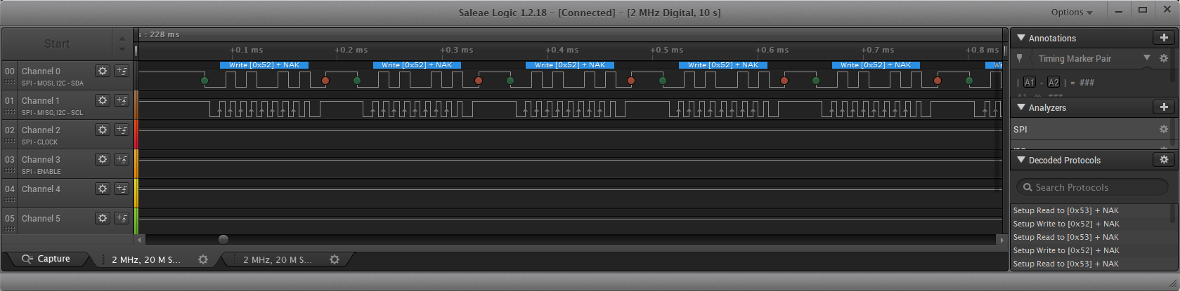
Saleae Logic Logikanalysator Screenshot SPI Protokoll
Saleae Logic 1.2.18 - [Connected] - [2 MHz Digital, 10 s] Options Annotations Start 228 ms +0.1 ms +0.2 ms +0.3 ms +0.4 ms +0.5 ms +0.6 ms +0.7 ms +0.8 ms 00 Channel 0 SPI - MOSI, I2C - SDA Write [0x52] + NAK 01 Channel 1 SPI - MISO, I2C - SCL Write [0x52] + NAK 02 Channel 2 SPI - CLOCK Write [0x52] + NAK 03 Channel 3 SPI - ENABLE 04 Channel 4 05 Channel 5 Analyzers SPI Decoded Protocols Setup Read to [0x53] + NAK Setup Write to [0x52] + NAK Setup Write to [0x52] + NAK Setup Read to [0x53] Capture 2 MHz, 20 M S...
in „Problem mit VL53L0X über P82B96“ · Mikrocontroller und Digitale Elektronik · · Oszi-Bilder
-
PDF
P82B715.pdf
capacitance like the P82B96 or PCA9600 are able to do. The primary disadvantage of the P82B96 and PCA9600 is that the static level offset needed to isolate bus capacitance does not allow these devices to operate with other bus
in „Arduino I2C Probleme Sonsoren werden manchmal nicht gefunden“ · Mikrocontroller und Digitale Elektronik ·
-
PDF
CAN_uC_V2_02Mar2011.pdf
100R R8 4K7 RN4 100R nMCLR 1W_DQ nRST_EXT R7 1K n n Bestückungsvarianten: 0 n n n n 0 TWI-Puffer P82B96 und Pico-Gate AND 1 RN5 RN6 1 1 1 1 1 VCC TJA1054 oder TJA1041 oder TJA1040 VCC zum Entkoppeln von SPI und TWI: 3 100R 100R 0 5 6 7 Bei nCsSPI LOW wird der TWI-Bus C21 C C C C C C von den SPI Leitungen abgekoppelt. 100n Ein TJA1040 wird dabei mit seinem C22 100n Wegen P82B96 + PULL-UP PIN1 auf PAD1 und mit PIN8 auf PAD14 verbleibt der TWI-BUS HIGH (IDLE). 7 7 an den Platz für den TJA1041 bestückt. n IC7 4 4 GND w G D GND 6 7 WAKEUP _ B _ P X A VCC R R U_IN p S r n 1 2
in „Anforderungssammlung CAN Hausbus mit PIC µC“ · Haus & Smart Home ·
-
PDF
an10160.pdf
restrictions on making series connections between any of the following groups… a) The Tx/Rx side of P82B96 b) Either side of the PCA9511/12/13/14 c) Either side of P82B715 d) Either side of just one PCA9515/16, OR just one Sx connection of a single P82B96 The selected system impedance levels, voltages,
in „Bussystem mit AVR für Baugruppenträger“ · Mikrocontroller und Digitale Elektronik ·
-
PDF
an10160.pdf
restrictions on making series connections between any of the following groups… a) The Tx/Rx side of P82B96 b) Either side of the PCA9511/12/13/14 c) Either side of P82B715 d) Either side of just one PCA9515/16, OR just one Sx connection of a single P82B96 The selected system impedance levels, voltages,
in „18 x SHT11 an welchem Mikrocontroller“ · Mikrocontroller und Digitale Elektronik ·
-
 Bild
Bild
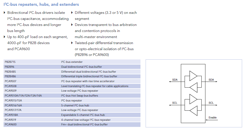
Übersicht I2C-Bus Repeater, Hubs und Extender
multi-master environment Twisted-pair differential transmission or opto-electrical isolation of I2C-bus (P82B96 or PCA9600) P82B715 I2C-bus extender P82B96 Dual bidirectional I2C-bus buffer P82B485 Differential dual bidirectional I2C-bus buffer P82B486 Differential triple bidirectional I2C-bus buffer PCA9507
in „Ansteuerung einer Anzeigetafel - Federal Vama Traffic Storm“ · Fahrzeugelektronik · · Screenshots
-
PDF
Einstellbare_Laufzeitleitung_f_italsignale.pdf
IO1 IO2 P82B96 IC1a P82B96 CD4015 K1 STIFTLEISTEK2X4 D1 Bus SDA SDA TX D Q1 1 2 RX CAN-TX Q2 3 4 CLK Q3 5 6 RES Q4 7 8 IC2a K2 STIFTLEISTEK2X4 CD4015 RX TX Bus D3 SDA 1 2 Q1 D 3 4 Q2 SDA 5 6 Q3 CLK 7 8 Q4 RES IC1b
-
PDF
AN10216.pdf
9564 SCL • Products: Device 2 P82B715 • Multi-Master capability or 2 isolated Iwith the same device P82B96 DesignCon 2003 TecForum I C Bus Overview 68 PCA SDA1 Master 9564 SCL1 SDA2 SCL2 Slide 68 • Products Voltage range Max I C freq Clock sourceParallel interface The P82B715 and P82B96 are designed for
in „AVR TWI: Hängt nach dem Flaschen“ · Mikrocontroller und Digitale Elektronik ·
-
PDF
CAN_uC_V2_NurCPU_24Jun2011.pdf
Prozessor" VCC 1 2 3 4 VCC als Fläche R1 10K ausgelegt 100n C11 C12 100n 2 1 1 2 nCS_SPI mit dem als nCS P82B96 und Pico-Gate AND IC2 24Cxx verwendeten IO verbinden ! zum Entkoppeln von SPI und TWI: 8 7 6 5 P82B96 IC3 1 A0 VCC 8 1 7 5 VCC A 1 R Bei nCsSPI LOW wird der TWI-Bus R 4 B 2 0 p I _ _ _ _ K C Q von
in „Anforderungssammlung CAN Hausbus mit PIC µC“ · Haus & Smart Home ·
-
PDF
CAN_uC_V2_CPU_27Aug2011.pdf
D D _S _ _ I I I I _ _ _ IC2 2 1 24Cxx X X C P P G G G G P C 1 r VCC A R T n S S S R t 3 1 1 201 P82B96 IC3 5 1 2 E 1 A0 VCC 8 R R R R B 2 R 2 A1 WP 7 1 Sc VCC 8 4 Y GND 3 A2 SCL Rc Sd VCC 3 6 2 7 IC1 4 VSS SDA 5 3 Tc Rd 6 4 GND Td 5 NC7S08M5 GND 4 R p GND-Insel p TWI EEPROM N 0 2 2 ODER R 1 2 Q1 2 FM24V10 FRAM 4 3 2 1 4 3 2 1 4 3 2 1 1 32,768KHz 1 GND GND 3 GND 3 C 1 VDD P82B96 und Pico-Gate AND 1 2 C DQ IC4 zum Entkoppeln von SPI und TWI: 5 6 7 8 5 6 7 8 5 6 7 8 2 DS18B20 Bei nCsSPI LOW wird der TWI-Bus 0 9 8 7 3 R 2 R GND-Insel, GND an VSS GND von den SPI Leitungen abgekoppelt
in „Anforderungssammlung CAN Hausbus mit PIC µC“ · Haus & Smart Home ·
-
PDF
CAN_uC_V2_01Jan2013_Stromlauf.pdf
O D K C C D _ _ _ _ _ _ _ D _ S _ S S D D D I I I I C P P I 2 I I _ R T G G G GP n S S S R T T 1 P82B96 und Pico-Gate AND* zum Entkoppeln von SPI und TWI: 9 1 GPIO_5 0 2 Bei nCsSPI LOW wird der TWI-Bus 1 3 GPIO_6 von den SPI Leitungen abgekoppelt. VCC VCC K GPIO_7 (* = AN255-02 Philips (NXP)) 4 GPIO_
in „Anforderungssammlung CAN Hausbus mit PIC µC“ · Haus & Smart Home ·
-
PDF
PCA9515_NXP.pdf
precautions when using more than one PCA9515 in a system or using the PCA9515 in conjunction with the P82B96. PCA9515_9 © NXP B.V. 2009. All rights reserved. Product data sheet Rev. 09 Ñ 23 April 2009 4 of 16 NXP Semiconductors PCA9515 I C-bus repeater 7. Application design-in information A typical application
in „I2C Repaeter PCA9515A“ · Mikrocontroller und Digitale Elektronik ·
-
PDF
kicad_8450_dcm_liste_neu_v3.pdf
Clock Oscillator XO91 HCMOS Clock Oscillator philips HTRC11001T HITAG RF Reader Device, SOIC-14 P82B96 Dual I2C Bus Buffer, DIP8/SO8/TSSOP8 PCA82C251 CAN Transceiver for 24V Systems, SOIC-8 PCA9516 5 channels I2C Hub, SO/TSSOP16 PCF8563 Realtime Clock/Calendar I2C Interface, DIP/SOIC/TSSOP-8 PCF8574
in „KiCAD Eeschema, Bibliotheksdokumentation *.dcm als PDF-Datei“ · Platinen ·