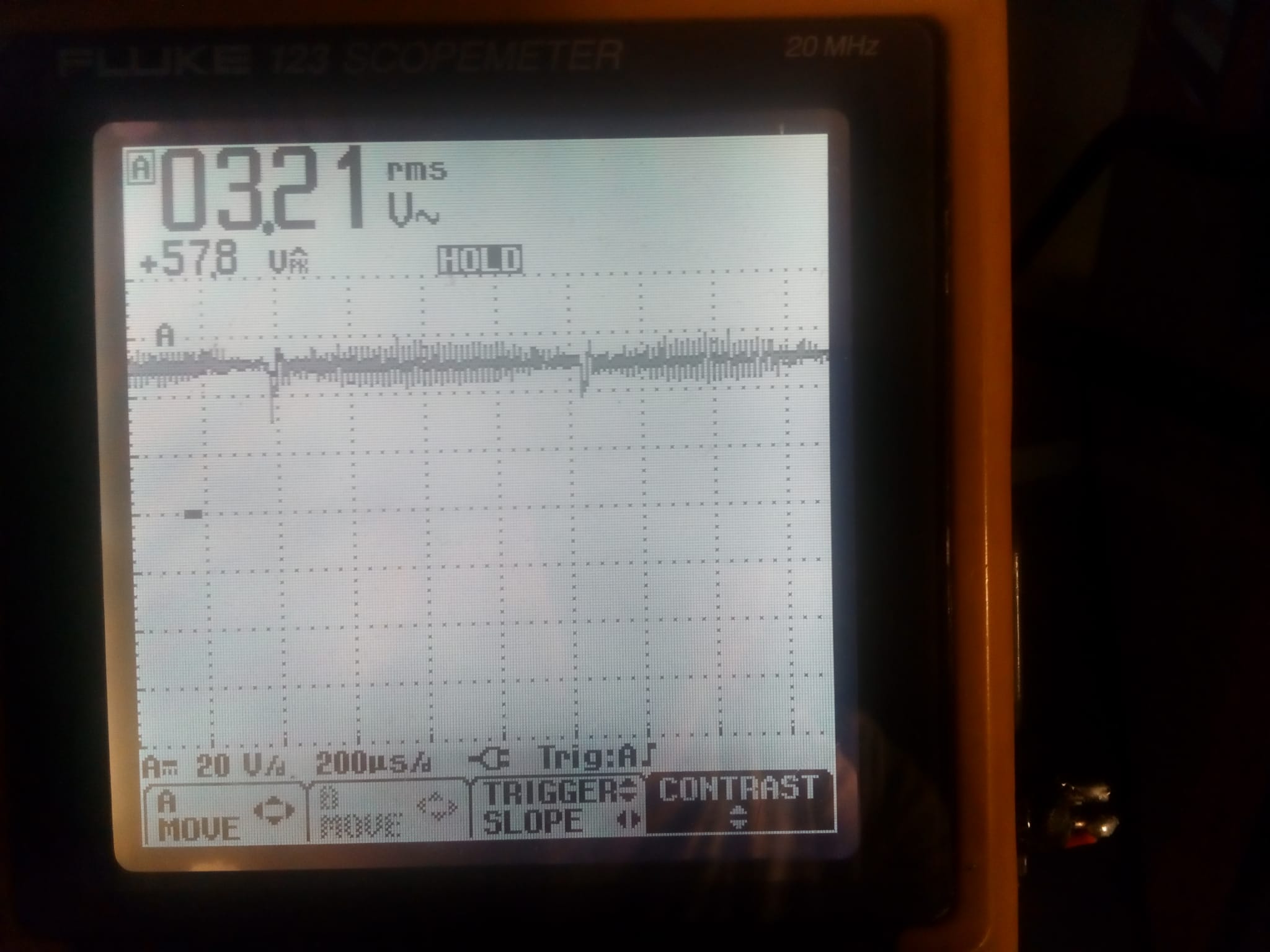
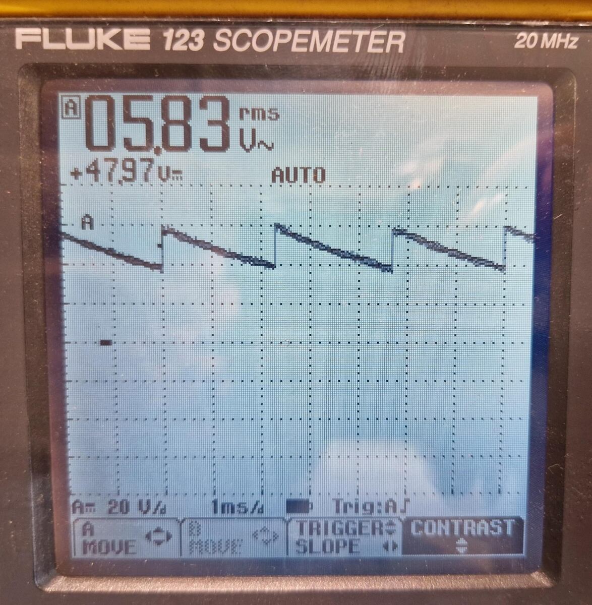
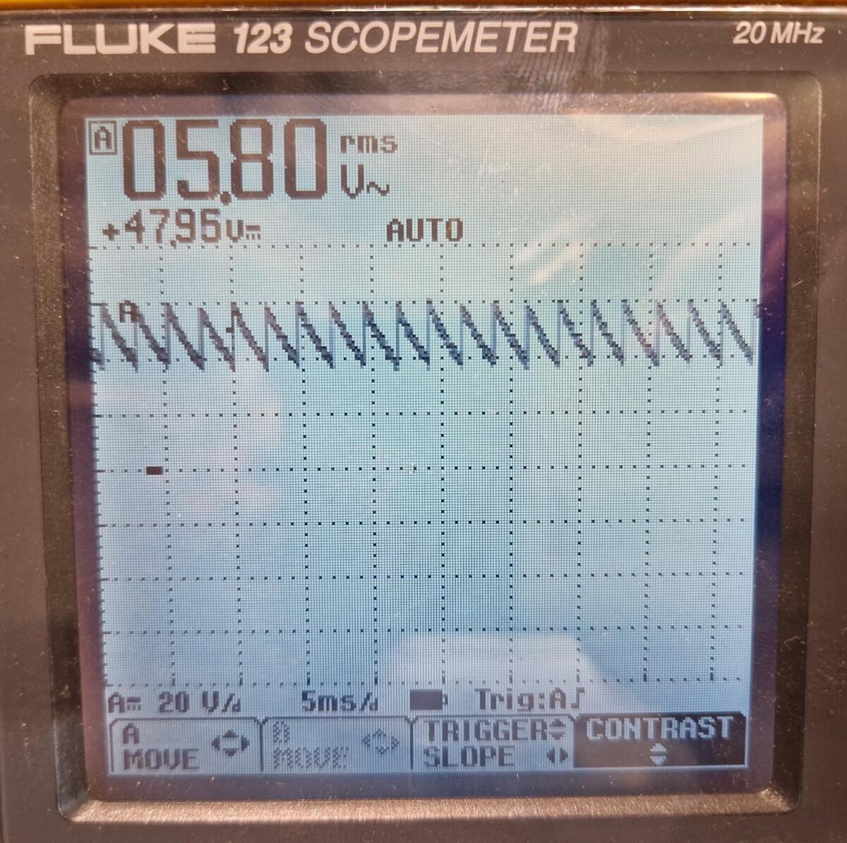
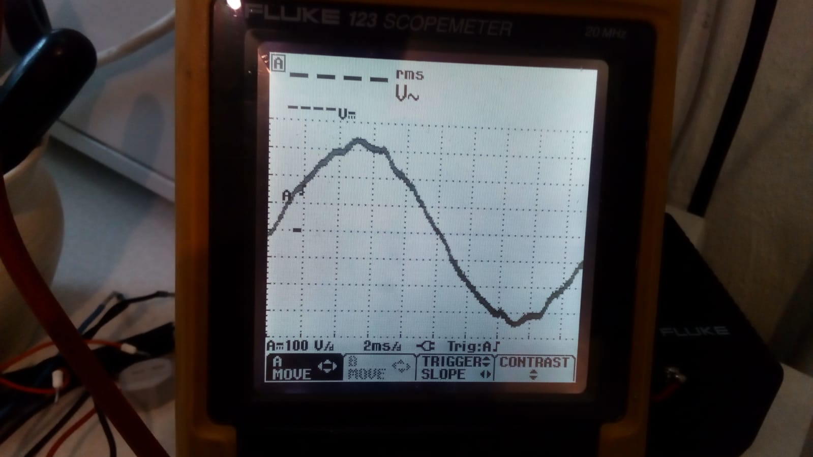
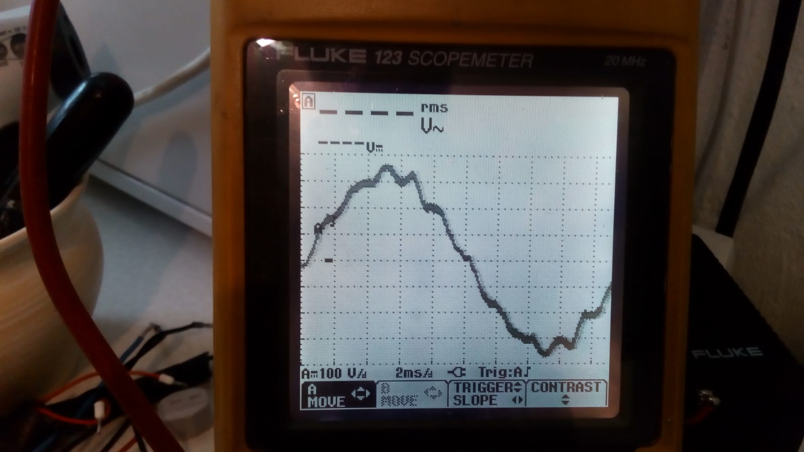
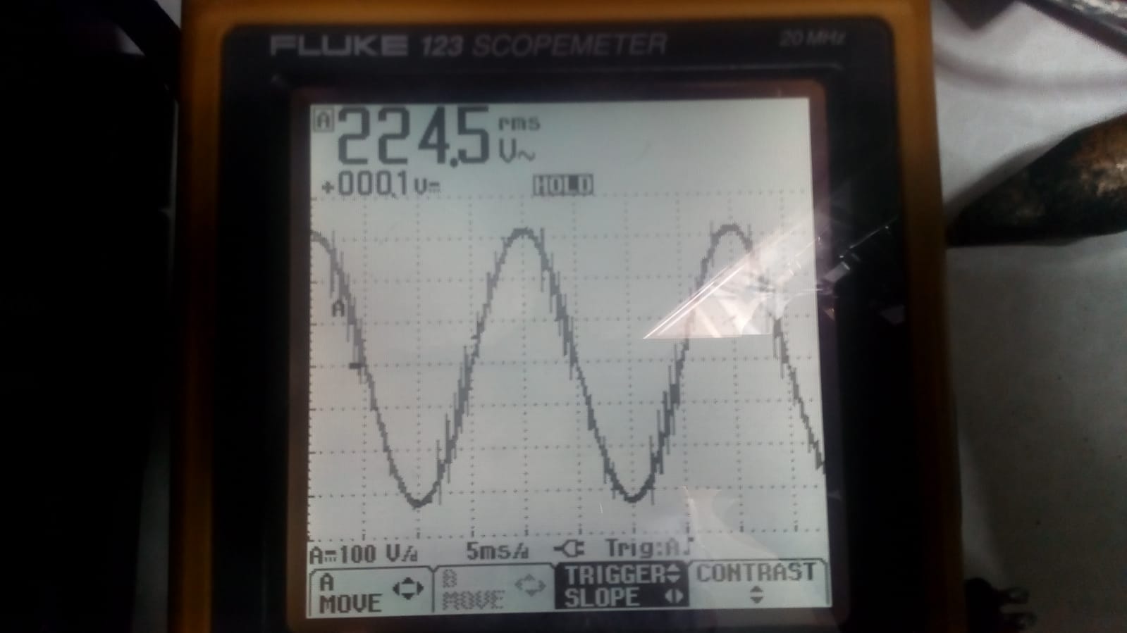
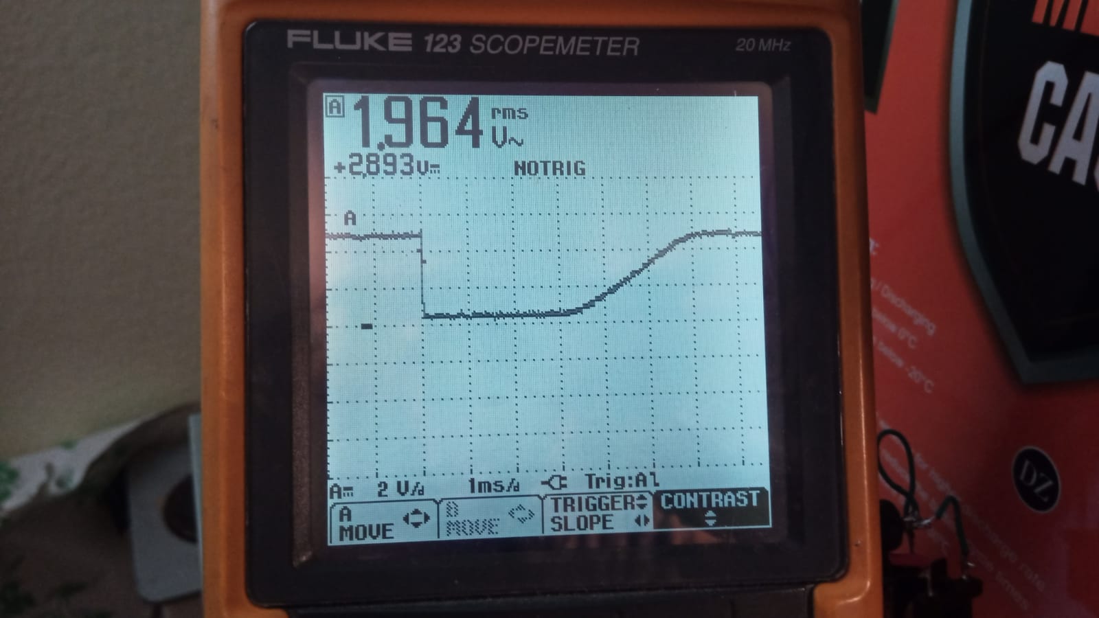
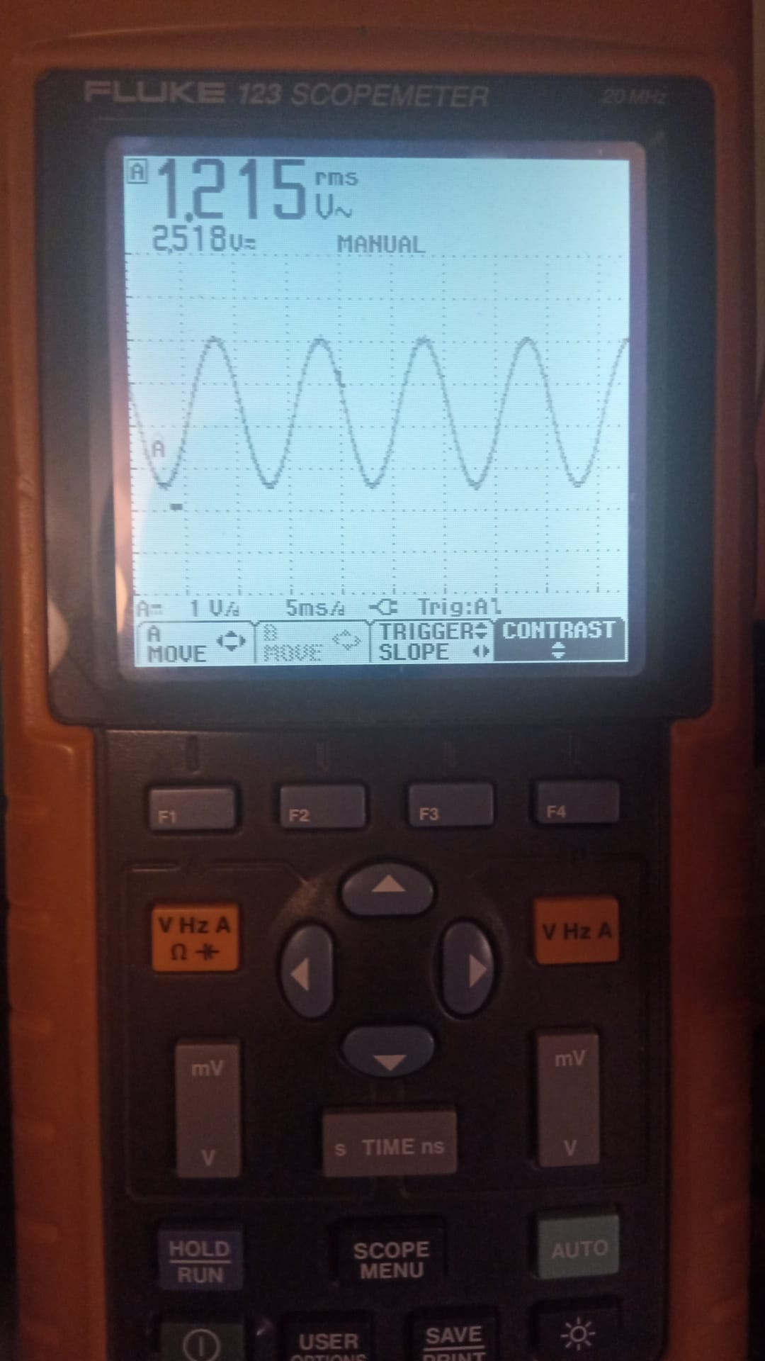
FLUKE 123 SCOPEMETER 20 MHz
1.215 rms V~
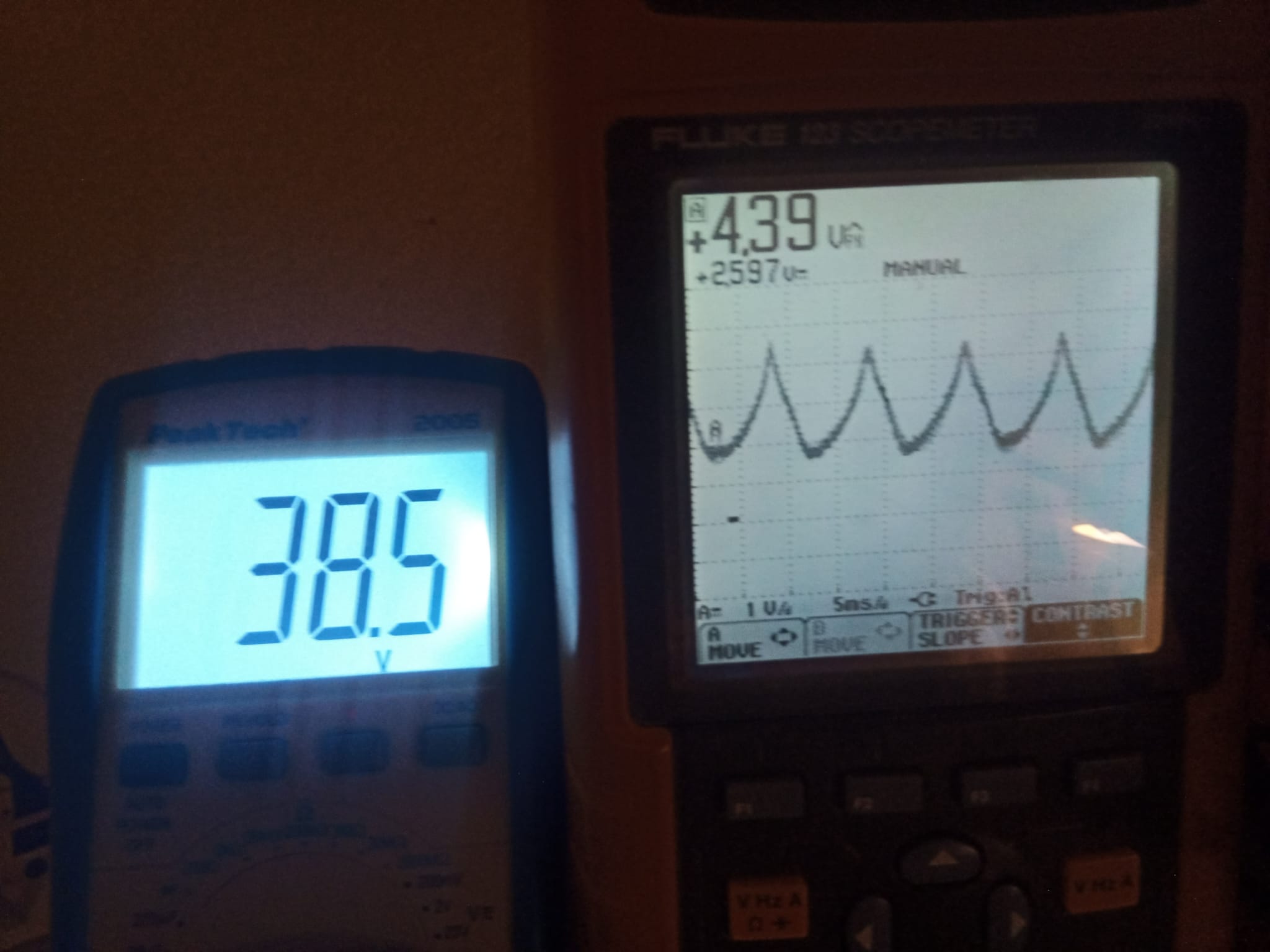
2.518 uV MANUAL
A 1 V/div 5ms/div Trig: A1
A MOVE TRIGGER CONTRAST
SLOPE
V Hz A Ω +
F2
F3
F4
mV V
s TIME ns
HOLD RUN SCOPE MENU AUTO
Für Anwendungen im Bereich ( Nähere Informationen finden Sie auf der Fluke Website) der Industrieelektronik und 199C 196C 199B 196B 192B 124 123 Elektromechanik bieten sich Technische Daten der ScopeMeter die Industrie-ScopeMeter der Bandbreite 200 MHz 100 MHz 200 MHz 100
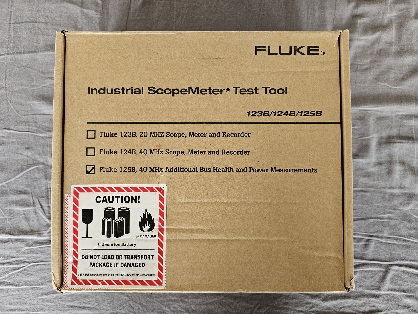
FLUKE®
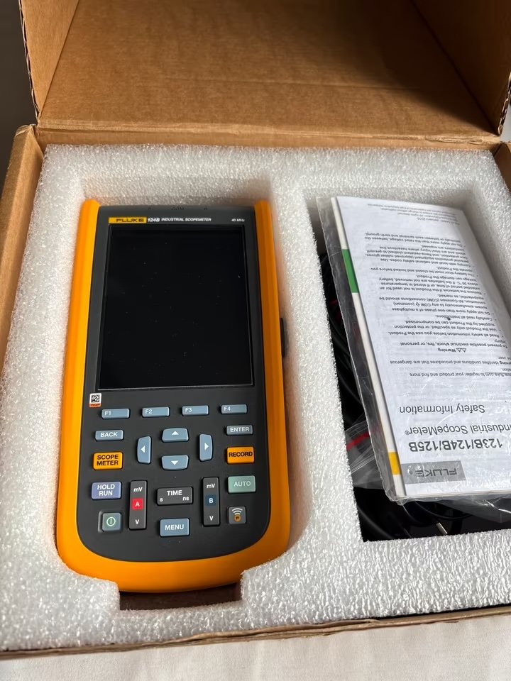
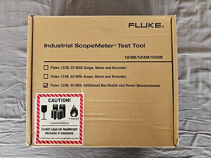
Industrial Scopemeter® Test Tool
123B/124B/125B
Fluke 123B, 20 MHZ Scope, Meter and Recorder
Fluke 124B, 40 MHz Scope, Meter and Recorder
Fluke 125B, 40 MHz Additional Bus Health and Power Measurements
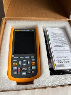
FLUKE 124B INDUSTRIAL SCOPEMETER Safety Information Industrial Scopemeter 123B/124B/125B F1 F2 F3 F4 BACK ENTER SCOPE METER RECORD HOLD RUN mV TIME mV B A V MENU V
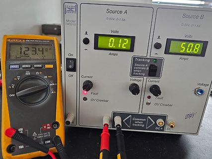
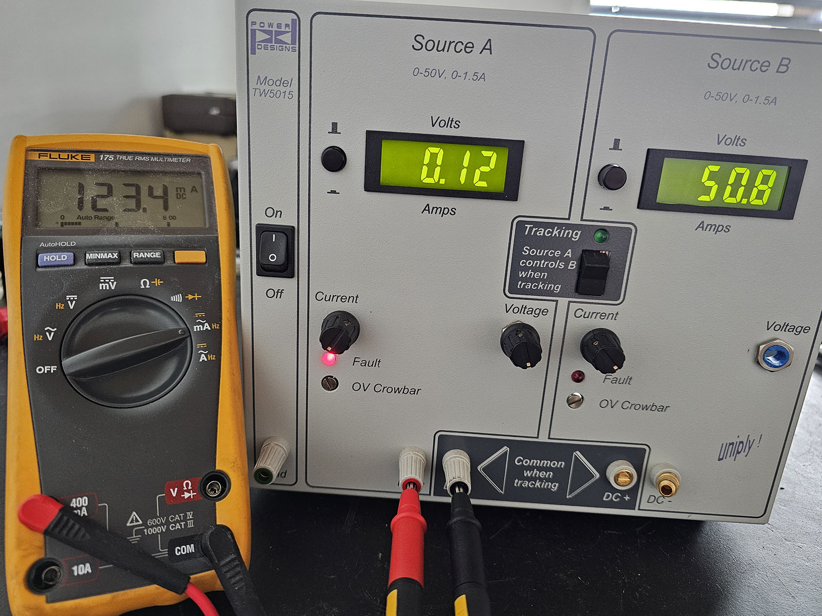
tracking On Off Current Voltage Current Voltage Fault Fault OV Crowbar OV Crowbar uniply! DC+ DC- FLUKE 175 TRUE RMS MULTIMETER 123.4 mA Auto Range 400V CAT II 1000V CAT III COM
microprocessor waits for the input to settle. The “D” Input of U122A also goes to a logic “1” and is gated 10 U123B through U127B. This clears the 16 bit counter U123B. The Q output of U122A will enable the input signal to the integrator on the next rising edge of the 2.5kHr clock. The microprocessor waits 16.66
philcolon44776 Schottegatweg Oost 146 Oesterreichische Phillps Canada P O Box 3523 Industrie G m b H Fluke Electronics Canada Inc. Sistemas E Instrumentation, Ltda. Willemstad, Curacao GeschaftsberelchI& E 400 Britannia Rd. East Unit#1 (ForFluke products) Tel:599-9-615277 MarktbereichTest und Mississauga
the Models 196/199 Digital Multimeter user manuals for more information about re- mote programming. FlukeModel8840A/8842ADigitalMultimeter The Model 2000 Multimeter implements virtually all commands available in the Fluke Models 8840A and 8842A digital multimeter, except for the self-test and calibration
following equipment: Camera 7 RF part 8 Nokia repair SW : Phoenix version 2006.12.7.138 Oscilloscope : Fluke PM 3380A/B Signal overview 9 Spectrum Analyzer : Advanced R3162 with an analog probe Component finder 10 RF-Generator/GSM Tester : Rhode & Schwarz CMU 200 Multimeter : Fluke 73 Series II errors may
clipped signals (by CR1) from Q2 (A) trigger one half of an adjustable pulse width one-shot, 74HCT123 at U2A. Pulsed blank- ing signals are output to BIPA via J5. Pulse widthcontrolisachievedfromthefrontpanel via the J5 connector as shown. A separate 9 MHz IF narrow signal coming from IF9RX isfedtotheassemblyviaJ3
, but has peak currents of up to 1.2mA for control. 7 The Fluke multimeter was not calibrated and the deviation from the ideal value is unknown. Chapter 7. RESULTS 95 Figure 81 shows 151 individual measurements and their distribution within a 22mV range. While the arithmetic mean of the measured values is 3351.5mV, the Fluke multimeter shows 3357.7mV. The individual measured values vary from the mean value by up to ±6.5mV, whereby two measured values (3363.0mV and 3341.0) are still far outside this range. Therefore, in
860 SPS only requires approximately 1.2 ms, so the ADS111x enter power-down state for the remaining 123.8 ms. In this configuration, the ADS111x consume approximately 1/100th the power that is otherwise consumed in continuous-conversion mode. The duty cycling rate is completely arbitrary and is defined
with a PT100 temperature sensor. The temperature calibration of these chambers was performed with a Fluke 1524 reference thermometer and a Fluke 5622-05 PT100 probe. These thermal chambers were able to reduce temperature variations to less than 0.2°C and they were used for measurements at 25°C, 40°C, and
Art of Electronics Third Edition Additional Exercises for Chapter 1 66 2.6.1 Regulated power supply 123 Review of Chapter 1 68 2.6.2 Temperature controller 123 2.6.3 Simple logic with transistors TWO: Bipolar Transistors 71 and diodes 123 2.1 Introduction 71 Additional Exercises for Chapter 2 124 2.1.1
diodes and transistors in many applications. Only high-quality, interference-proof instruments (e.g. Fluke 75) are suitable for measuring output voltage. On TIG systems, do not attempt to measure on the load side of the HF reactor (X3) as the voltage of the HF pulses is so high that it could destroy the
coils]. [Ollendorff 1926]. 31 Theory of the Beam-Type TWT. J R Pierce. Proc. IRE. Feb. 1947. p111-123. SeeAppendix B, p121-123, "Propagation of a wave along a helix", which gives Schelkunoff's derivation of propagation parameters for the Ollendorff helix. 32 Travelling Wave Tubes. J R Pierce. Bell System
100 1.34 and the output voltage was measured with an oscilloscope and 10X probe. The Q3 output was 123 mW, 7 V peak-to-peak 4. 7K at the load, with Rl=270 £2 in the buffer. 390 Changi ng RI to 150 £2 increased output to 314 mW. The DC current, 43 mA, was de- 2 . 2 K termined by measuring the voltage

 Bild
Bild
 Bild
Bild
 Bild
Bild
 Bild
Bild
 Bild
Bild
 Bild
Bild
 Bild
Bild
 Bild
Bild
 Bild
Bild
 Bild
Bild
 Bild
Bild
 Bild
Bild
 Bild
Bild
 Bild
Bild