
-
PDF
-
Datei
sc_math.lib.dis.txt
, r0, #1 56: 2800 cmp r0, #0 58: d0f9 beq.n 4e <sc_math_tan+0xe> 5a: 48e9 ldr r0, [pc, #932] ; (400 <__wrap___ltsf2+0x2a>) 5c: 6880 ldr r0, [r0, #8] 5e: 4770 bx lr 00000060 <sc_math_asin>: 60: 4601 mov r1, r0 62: 2001 movs r0, #1 64: 4ae6 ldr r2, [pc
in „Neue MCU APM32F103“ · Mikrocontroller und Digitale Elektronik ·
-
 Bild
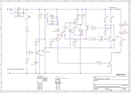
Schaltplan einer Bausteuchtenleuchte
S1 ON OFF R4 470k R6 39k CONT S2 FLASH D1 1N4148 R11 18k R12 33k 2SC2001 Q5 R10 88k R17 27k R15 R13 270k LED Q3 orange ultra-bright R16 12k LED Q6 orange ultra-bright D2 1N4148 D3 1N4148 10 uF / 25V R18 1,5k C2 Q7 2SC946 R7 180k R5 2,7M R2 100k R3 33k Q2 2SC945 Q1 2SC945 C1 47 uF / 16V R8 1,8k Q4 2SC2001 000416-2 TC-92 Q1, Q7 2SC2001 2SA952 2SC945 Q0 Opto Translator E C B C E Title Bausteuchtenleuchte - Nitra 003 Author File xd_SchaltplaeneBausteuchtenleuchteNitra
in „Baustellenleuchte Blinkschaltung“ · Analoge Elektronik und Schaltungstechnik · · Schaltpläne
-
PDF
grundig_chassis_t5_19_22vle2000t_22-2010t_22-2940t_22-2942t_19hd_br_wp_cba_16-2941tc_19-2940t.pdf
SC1_DAC_LOUT SC1_DAC_LOUT B7_RXE2- B6_RXE2+ C491 R456 SC1_DAC_ROUT B6_RXE2+ B3_RXE3- 100nF 0R SC1_DAC_ROUT AU_DACO_L B3_RXE3- B2_RXE3+ R458 AU_DACO_L AU_DACO_R B2_RXE3+ IC405 GND R457 10K AU_DACO_R B1_RXE4
in „Grundig Fernseher defekt“ · Analoge Elektronik und Schaltungstechnik ·
-
Datei
AN_111.bas
LSB 'Sc(2) 'Temperature MSB 'Sc(3) 'TH/user byte 1 also SRAM 'Sc(4) 'TL/user byte 2 also SRAM 'Sc(5) 'config also SRAM x R1 R0 1 1 1 1 1 - the r1 r0 are config for resolution - write FF to byte for 12 bit -
in „ds18s20 mit Bascom unter Proteus“ · Mikrocontroller und Digitale Elektronik ·
-
Datei
parts.txt
2SB507 4 2SC1013 1 2SC1017 50 2SC1018 6 2SC1096 6 2SC1124 10 2SC1226 3 2SC1239 4 2SC1306 2 2SC1369 9 2SC1413 1 2SC1675 150 2SC1678 100 2SC1728 2 2SC1728 2 2SC1815 10 2SC1815 10 2SC1947 37 2SC1957 60 2SC1964 3 2SC2029 25 2SC2076 14 2SC2091 2 2SC2092 3 2SC2787 1 2SC3042 80 2SC3274 3 2SC369 3 2SC371 1 2SC372 140 2SC373 30 2SC381 8 2SC394 2 2SC458 2 2SC460 8 2SC469 200 2SC481 6 2SC495 30 2SC509 20 2SC535 10 2SC536
in „[V] Bauteilauflösung Transistoren/Audio+Video IC“ · Markt ·
-
 Bild
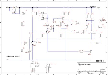
Schaltplan einer Bausteuchten-Steuerung
S1 ON OFF R4 470k R6 39k CONT S2 FLASH D1 1N4148 D2 1N4148 LED orange ultra-bright R11 18k R12 33k R10 88k R9 1,2k R17 27k R15 R13 270k LED orange ultra-bright D0 R16 12k D3 1N4148 R7 33R C2 1,5uF 2SC946 Q7 R2 100k R3 33k Q2 2SC945 Q1 2SC945 C1 47uF 16V R5 2,7M R14 6,7k R8 1,8k Q4 2SC2001 000416-2 Q1, Q2 2SC2001 2SA952 2SC945 Q0 Opto Translator E C B C E Title Bausteuchten-Leuchten - Nitra 005 Author File xd_SchaltplaeneBausteuchtenleuchtenNitra
in „Baustellenleuchte Blinkschaltung“ · Analoge Elektronik und Schaltungstechnik · · Schaltpläne
-
PDF
ass--IC2001-USB--de-en.pdf
Verdrahtungsempfehlung Lieferumfang für Sensoren TX+ 1 1800±30 - IC2001/USB Einkanal RS422/USB Konverter-Kabel - 1 Montageanleitung - der Reihe optoNCDT ILD1220 / 1320 / 1420 / 1750 / 1900 / 2300 TX- 2 1 - der Reihe optoNCDT ILR2250 2 - der Reihe optoCONTROL 2500 / 2520 / 2600 RX+ 3 RX- 4 GND 5 30±2 Sensor Maßzeichnung IC2001/USB, Abmessungen in mm Farbe und zugehörige Funktion der Kabeladern Position Farbe der LED Bedeutung Anschluss des IC2001/USB an PC und Sensor 1 Grün Daten empfangen (Rx) Verbinden
in „Sensor mit RS422 interface und Konverter verbunden an Esp32 via TTL“ · Mikrocontroller und Digitale Elektronik ·
-
PDF
osd_draft.pdf
L2007 0.47uH L2008 0.47uH 2 2 0 . 4 . TP2003 R 3 0 2 . R2013 Q2004 0 R N 2 10k R2046 2SC2412K C 100 1 2 2 Q2007 Q2003 C L2001 L2002 L2003 E2004 R2030 2SC2412K IMX2 4.7uH 4.7uH 4.7uH 47/35 100 R2039 E2007 Z2001 6 . 470/16 2 1 R2010
in „Taktquelle umschalten“ · Mikrocontroller und Digitale Elektronik ·
-
PDF
MAX9812-MAX9813L.pdf
2 VCC - 0.1 VOH V CC- VCC - Output Voltage Swing RL= 1kΩ to VCC/2 0.25V 0.1V V RL= 10kΩ to VCC/2 0.1 VOL RL= 1kΩ to VCC/2 0.1 0.25 Output Short-Circuit Current IOUT_SC Sinking or sourcing 3 12 24 mA Small-Signal
in „Richtiger Anschluss einer Elektretkapsel“ · Analoge Elektronik und Schaltungstechnik ·
-
PDF
bpw21.pdf
coefficient ofSC Rauschäquivalente Strahlungsleistung NEP 7.2 × 10– 14 W Noise equivalent power ------- Hz VR = 5 V, λ = 550 nm Nachweisgrenze, V = 5 V, λ = 550 nm D* 1 × 10¹² R -------------- Detection limit W 2001-
in „eine Art Luxmeter basteln“ · Mikrocontroller und Digitale Elektronik ·
-
PDF
bpw21.pdf
coefficient ofSC Rauschäquivalente Strahlungsleistung NEP 7.2 × 10– 14 W Noise equivalent power ------- Hz VR = 5 V, λ = 550 nm Nachweisgrenze, V = 5 V, λ = 550 nm D* 1 × 10¹² R -------------- Detection limit W 2001-
in „Suche Sensoren“ · Mikrocontroller und Digitale Elektronik ·
-
PDF
10n120bnd.pdf
. . . . . . . L . . . . . . 260 . . . . . . . . T C Short Circuit Withstand Time (Note 2) a= 15V. . . . . . . . . . . . . . . . . . . . . . . . . .8. . . .t µs GE SC Short Circuit Withstand Time (Note 2GEa= 12V. . . . . . . . . . . . . . . . .SC . . . . . . . 15. . . .t µs CAUTION: Stresses
in „Netzteil mit IGBT“ · Analoge Elektronik und Schaltungstechnik ·
-
PDF
PWM_20schemes_20for_20BLDC.pdf
Overall Eff. Total Loss Ratio of Loss (V) (Arms) (W) (oz-in) (RPM) (%) (W) (pwm1 = 1) Sin SR 18.30 2.394 29.726 20.04 2005 67.84 14.09 0.978 Sin PhR 18.30 2.397 29.815 20.10 2005 67.96 14.06 0.976 pwm 4 18.30 2.459 29.637 20.02 2001 65.87 15.35 1.066 pwm 3 18.29 2.473 29.637 20.02 2001 65.51 15.60 1.083 pwm 2 18.30 2.404 29.637 20.02 2001 67.36 14.36 0.997 pwm 1 18.30 2.406 29.627 20.02 2001 67.28 14.41 1.000 pwm 0 18.30 2.430 29.622 20.00 2002 66.62 14.84 1.030 DriveType InputVtg Input C'rt Output Torque
in „Diskrete H-Brücke“ · Analoge Elektronik und Schaltungstechnik ·
-
PDF
DUAL-MODE_CRYSTAL_OSCILLATOR.pdf
for a variety of SC cut designs inspected, and where υ is any variable, etc. supply voltage, load, temperature, etc. Using f-T dependence of the two modes as follows ∆fM 2 3 =a M ∆T+ bM ∆T + cM ∆T (3) fM where the normalized
in „Zwei RTCs für niedrigere Abweichung "parallel"“ · Mikrocontroller und Digitale Elektronik ·
-
PDF
DUAL-MODE_CRYSTAL_OSCILLATOR.pdf
for a variety of SC cut designs inspected, and where υ is any variable, etc. supply voltage, load, temperature, etc. Using f-T dependence of the two modes as follows ∆fM 2 3 =a M ∆T+ bM ∆T + cM ∆T (3) fM where the normalized
-
PDF
On_Chip_Debug_Spec_51242a.pdf
for PIC16C87X devices (DS39025) for more information on programming the configuration word. Figure 2.1: CONFIGURATION WORD CP1 CP0 BKBUG - WRT CPD LVP BODEN CP1 CP0 PWRTE WDTE F0SC1 F0SC0 Register:CONFIG bit13 bit0 Address 2007h bit 11: BKBUG: On-chip Debugger Mode (This bit documented as reserved in
in „PIC12F509 hidden features und "High Flash"“ · Mikrocontroller und Digitale Elektronik ·
-
PDF
marshall_mg100rcd_sch.pdf
TR9 CCD2 JS5 RED 1N4148 2SC3519-P 1/50V EPJ-BBB-P(8)ST R84 820 D5 1N4007 C58 JS6 101P D4 R88 EPJ-BBB-P(8)ST 1N4148 68 BLACK TR7 SC549 R96 R80 R83 TR6 1.2K 330K 2.2K KTD1415 R123 220 1/2W C56 R79 IC8A R95 R97 IN C224 6.8K NJM4558DD 470 0.33 5W 2 - RED R86 1 3 + C59 8.2K BLACK 103P R98 R105 R107 3 4 330 R99 C62 3 1K 1W 22K VCC R81 R85 R87 0.33 5W M224 220 820 1.5K TR8 SC559 JS7 R181 R100 HTJ-063-11I 33K C57 1K 471P D6 R109 R103 C63 R108 1N4007
in „Marshall G100R CD“ · Analoge Elektronik und Schaltungstechnik ·
-
PDF
panasonic_tx-p50u20b_e_tx-pr50u20_chassis_gpf13de_sm.pdf
D9807 12 9 25V 25V B0ADCJ000100 CERS 5 SC_CERS SC_CERS Y6 PD_SCCLK 10u 10u 2 VIN 7 TP9084 SC_CRC2 13 2 A7 8 P3.3V EN C9831 SC_CRC2 Y5 9 PD_CERS L9802 R9908 50V R9039 CRC2 6 SC_OC2 14 0 6 A6 7 G1C100MA0416 +3.3V 12k 2700p 47k SC_CRC1 SC_OC2 2
in „Panasonic TX-P50U20E“ · Analoge Elektronik und Schaltungstechnik ·
-
 Bild
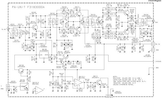
Schaltplan einer PA-Unit F3183000A
PA-UNIT F3183000A Circuit Diagram TX RF T GND Q6101 2SC2166 Q6102 2SC3133 Q6104 2SC2879 Q6105 2SC5000 Q6106 R0100970 Q6107 2SD8820 Q6108 2SA12830 Q6109 BA1A4P Q6110-1 MS218AL Q6110-2 MS218AL Q6111 2SC2001L
in „Mein FT1000MP Field ist kaputt.“ · HF, Funk und Felder · · Schaltpläne
-
PDF
LDO_Oscillosation.pdf
+ SC O R R + 1 SC R +1 d ESR SC = b ds = O Rds 1 1 SC R +1 + RESR+ SC Rds+ (SC b ds+ 1)RESR+ (SC b ds+ 1)SC b ds O O 2 AN025 SC O Rds ESR+ R ds = 2 SC O +ds C C R O b ds ESR+ SC O ESR + SC b ds Rds(SC O ESR+1 ) ≈ (SC R +1 SC R( +1) …(3) O ds b ESR Based on the equation3 above, zero (Z ESR) and poles (Po, Pa, and Pb) can be found as follows. Z = 1 ESR 2πR ESRC O The first pole is 1 PO= 2πC O ds The
in „Low Drop Netzteil (Diskret) / Theoretischer Versuch“ · Analoge Elektronik und Schaltungstechnik ·
-
PDF
opa4348_1_.pdf
RAIL-TO-RAIL INPUT AND OUTPUT OPA348 series is useful for low-power applications on single ● SINGLE SUPPLY: +2.1V to +5.5V supplies of 2.1V to 5.5V. ● INPUT BIAS CURRENT: 0.5pA Low supply current of 45µA, and an input bias current of ● Micro SIZE PACKAGES: SC70-5, SOT23-8 and 0.5pA, make the OPA348 series an
in „ADC im Messbereich kleiner 1V“ · Mikrocontroller und Digitale Elektronik ·
-
 Bild
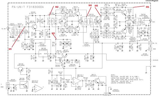
Schaltplan PA-UNIT F3183000A
PA-UNIT F3183000A Circuit Diagram M2 C6153 0.0047 B T6102 L0021969 Q6101 2SC2166 R6104 10k C6101 0.047 uF R6103 1.2k T6101 L001351 Q6108 2SA12830 M1 C6134 25uF R6126 1k R6123 1k R6127 10k Q6110-2 MS218AL R6130 10k R6131 470k C6142 0.047 uF Q6111 2SC2001L R6132 1.5k C6139 10uF T6103 L0021970 Q6102 2SC3133 R6138 10k C6159 500V XB R6117 C6121 0.047 uF R6112 3.3 uF Q6116 2SC2879 C6160 500V XB R6118 1.2k C6124 22uF R6110 10k C6127 0.047 uF T6104 L0021404
in „Mein FT1000MP Field ist kaputt.“ · HF, Funk und Felder · · Schaltpläne
-
PDF
lmh6642.pdf
Swing RL= 2kΩ to V /2, VID= −200mV 25 75 Low R = 150Ω to V /2, V = −200mV 75 150 mV L ID SC Output Short Sourcing to V /2 Circuit Current V = 200mV (6) 35 50 95 ID mA Sinking to V /2 V = −200mV (6) 40 55 110 ID
in „Funkentstörung mobiler Kopfhörerverstärker“ · HF, Funk und Felder ·
-
PDF
2SC3940.pdf
Transistor 2SC3940, 2SC3940A Silicon NPN epitaxial planer type For low-frequency output amplification and driver amplification Unit: mm Complementary to 2SA1534 and 2SA1534A #.– . ".– . ■ Features . ● Low collector
in „2SC3940 Safe Operating Area“ · Analoge Elektronik und Schaltungstechnik ·
-
PDF
complex_signals.pdf
H (s) admittance for the capacitor according to jQ(s) = --------2------------- (21) sC → sC + jω C (23) 0 When the filters leading from the real and imaginary branches Letting of Fig. 14. do not exactly match, imaging errors (plus less harmful magnitude response errors
in „Komplexe Frequenz“ · Digitale Signalverarbeitung / DSP / Machine Learning ·
-
PDF
TC2014.pdf
DS21662F-page 4 2001-2012 Microchip Technology Inc. TC2014/2015/2185 Note: Unless otherwise indicated, V IN = VR+ 1V, I L 100 µA, C OUT = 3.3 µF, SHDN > V , IH= +A5°C. 60.0 2.705 VR= 2.7V 58.0 C = 3.3 µF 2.700 VIN 3.7V
in „Mcp3551 PT1000 Schaltung“ · Mikrocontroller und Digitale Elektronik ·
-
PDF
device_list_hilo_all03_v9-12.pdf
XL2864A XL2865A XL28C04/A XL28C16A/B XL28C256 XL28C64 XL28C64B XL28F010 XL28F020 XL46C15 <<FUJI>> *SC9005-162H0 *SC9005-22H0 *SC9005-42H0 *SC9005-82H0 *SC9006-162H0 *SC9006-82H0 *SC9008-162H0 *SC9008-22H0 *SC9008-42H0 *SC9008-82H0 *SC9011-162H0 *SC9011-22H0 *SC9011-42H0 *SC9011-82H0 *SC9013-162H0 *SC9013
in „PROM programmieren“ · Mikrocontroller und Digitale Elektronik ·
-
PDF
MAC97A8.PDF
values. cycles for sinusoidal currents; typical values. 9397 750 07917 © Philips Electronics N.V. 2001. All rights reserved. Product specification Rev. 01 Ñ 29 March 2001 5 of 12 Philips Semiconductors MAC97A8; MAC97A6 Logic level triac 003aaa041 1.6 003aaa039 3 IT(RMS) a (A) 1.4 2.5 1.2 2 1 0.8 1.5 0.6
in „µC 5V -> Triac 16VAC schalten“ · Analoge Elektronik und Schaltungstechnik ·
-
PDF
MAX6607-MAX6608.pdf
µC N.C.2 GND 2 GND 1nF A 3 4 VCC A 3 4 VCC GND SC70 SOT23 GND ________________________________________________________________ Maxim Integrated Products 1 For pricing, delivery, and ordering information, please
-
PDF
Vergleichsliste.pdf
ECG/TCG/NTE Best sub Next best Still should work ECG10 2SC3510 2SC3128 2SC2570A ECG11 2SD1246 ECG12 2SB1050 ECG13 2SD1330 ECG14 2SA825 ECG15 2SC2377 2SC2636 ECG16 2SD637 2SD636 2SC2063 2SD1199 ECG17 2SB745 ECG18 2SD638 2SD969 ECG19 2SB910 ECG20 2SD973 2SD1227
in „ECG45 was ist das?“ · Analoge Elektronik und Schaltungstechnik ·
-
PDF
2sc5707.pdf
Ordering number : ENN6913 2SA2040/2SC5707 PNP / NPN Epitaxial Planar Silicon Transistors 2SA2040 / 2SC5707 High Current Switching Applications Applications Package Dimensions • DC-DC converter, relay drivers, lamp drivers, unit
in „Dell TFT Reparatur“ · Mikrocontroller und Digitale Elektronik ·
-
PDF
HBruecke_TLE5205.pdf
16, 17, 18, 19 Data Sheet 3 2001-06-19 TLE 5205-2 Overview 1.4 Functional Block Diagram VS 2 6 EF ErrorFlag DiagnosisandProtectionCircuit1 1 3 IN OUT OUT1 IN1 1 2 1 2 0 0 1 0 0 1 0 1 5 1 0 0 0 7 OUT2 IN2 1 1 Z Z DiagnosisandProtectionCircuit2
in „FET auswählen“ · Analoge Elektronik und Schaltungstechnik ·
-
PDF
D130906D.pdf
. . . . . . . . . . . . . .L. . . . . . . . . . . . . . . . T C Short Circuit Withstand Time (Note 2)GEt V15V. . . . . . . . . . . . . . . . .SC . . . . . . . .4. . . .t µs Short Circuit Withstand Time (Note 2)GEt V10V. . . . . . . . . . . . . . . . .SC . . . . . . . 10. . . t µs CAUTION: Stresses above
in „Blitz Leistungsregelung“ · Analoge Elektronik und Schaltungstechnik ·
-
PDF
Datenblatt_Aleo_X61_Premium_260-270W.pdf
Produktgarantie 25 Jahre Kurzschlussstrom I [A] 8,27 8,43 8,60 Leistungsgarantie 25 Jahre – linear SC Wirkungsgrad h [%] 16,9 17,3 17,6 Brandbeständigkeit Klasse C Elektrische Werte bei Modul-Nennbetriebsbedingungen: 800 W/m 2; 20°C; AM 1,5; Wind 1 m/s Schutzklasse II Modultemperatur NMOT: 44,5°C Zertifzierung
in „Solaranlange Auslegung MPPT“ · Mikrocontroller und Digitale Elektronik ·
-
PDF
MC9S12DG128.pdf
Covers MC9S12DT128E, MC9S12DG128E, MC9S12DJ128E, MC9S12DT128, MC9S12DJ128, MC9S12DB128, MC9S12A128, SC515846, SC515847, SC515848, SC515849, SC101161DT, SC101161DG, SC101161DJ, SC102202, SC102203, SC102204, SC102205 HCS12 Microcontrollers 9S12DT128DGV2/D 03 Jun 2010 freescale.com Device User Guide — 9S12DT128DGV2
in „HCS12 CPU Disassembler“ · Mikrocontroller und Digitale Elektronik ·
-
PDF
DA74175765702C785FEFD64B394D9CB1.pdf
64-byte OTP Area and 64-byte Bit-addressable Area – 1 to 128-byte Program/Erase for Smart Cards – 2 ms Program, 2 ms Erase – Typically More than 500,000 Write/Erase Cycles – 10 Years Data Retention AT90SC6464C 64K Bytes of Flash Program Memory – 128-byte Page Programming – Minimum 10,000 Write/Erase
in „AT90SC6464C ??“ · Mikrocontroller und Digitale Elektronik ·
-
PDF
AT90SC6464C.pdf
EEPROM, Including 64-byte OTP Area and 64-byte Bit-addressable Area – 1 to 128-byte Program/Erase AT90SC6464C-USB – 2 ms Program, 2 ms Erase – Typically More than 500,000 Write/Erase Cycles – 10 Years Data Retention Summary 64K Bytes of Flash Program Memory – 128-byte Page Programming – Minimum 10,000 Write
in „AT90SC6464C ??“ · Mikrocontroller und Digitale Elektronik ·
-
PDF
TL431.pdf
2 VKA = Vref, KA = 10 mA 2470 2495 2520 mV SOT23-3, SC-70, Deviation of reference voltage VKA = Vref, 14 34 VI(dev) over full temperature range 2 KA = 10 mA, and TL432 devices mV (see Figure 1) TA= −40
in „Überspannungsschutz (Crowbar) für XPORT (3.3V)“ · Analoge Elektronik und Schaltungstechnik ·
-
PDF
Avrisp_Sch.pdf
17-Aug-2001 10:46:33 PAGE: 2 of 4 Document number: Revision:1.0 TITLE: AVR ISP Rs232.Sch 1 2 3 4 5 6 7 8 1 2 3 4 5 6 7 8 VCC TP1 TP2 TESTPIN TESTPIN Note : Just pin holes on PCB VCC VCC GND J2 1 1 1 MISO VCC 2
in „AVRisp serial upgrade failed“ · Mikrocontroller und Digitale Elektronik ·
-
PDF
Avrisp_Sch.pdf
17-Aug-2001 10:46:33 PAGE: 2 of 4 Document number: Revision:1.0 TITLE: AVR ISP Rs232.Sch 1 2 3 4 5 6 7 8 1 2 3 4 5 6 7 8 VCC TP1 TP2 TESTPIN TESTPIN Note : Just pin holes on PCB VCC VCC GND J2 1 1 1 MISO VCC 2
in „Fragen zu den Tutorials“ · Mikrocontroller und Digitale Elektronik ·
-
PDF
Avrisp_Sch.pdf
17-Aug-2001 10:46:33 PAGE: 2 of 4 Document number: Revision:1.0 TITLE: AVR ISP Rs232.Sch 1 2 3 4 5 6 7 8 1 2 3 4 5 6 7 8 VCC TP1 TP2 TESTPIN TESTPIN Note : Just pin holes on PCB VCC VCC GND J2 1 1 1 MISO VCC 2
in „MEGA8 direkt an schnittstelle?“ · Mikrocontroller und Digitale Elektronik ·
-
PDF
Avrisp_Schema.pdf
17-Aug-2001 10:46:33 PAGE: 2 of 4 Document number: Revision:1.0 TITLE: AVR ISP Rs232.Sch 1 2 3 4 5 6 7 8 1 2 3 4 5 6 7 8 VCC TP1 TP2 TESTPIN TESTPIN Note : Just pin holes on PCB VCC VCC GND J2 1 1 1 MISO VCC 2
in „Programmierboard im Selbstbau“ · Mikrocontroller und Digitale Elektronik ·
-
PDF
liebherr_self-test_and_fault_codes.pdf
Action Display Affected components Info / Test Action Display Component Display Component 1 Start SC + EA P1 Compressor on, interior light off Door should be open 1 Start Insert test-plug in socket X3 - 32°C LED green LED GT comp. On 2 Light test SC + 5 8 Interior light on On cold unit, display shows
in „Liebherr CNel4713 Servicemü Informationen gesucht - NoFrost Eisfachteil vereist, Kühlteil aus“ · Haus & Smart Home ·
-
PDF
MC34063A.pdf
100 mV Efficency V IN25V, O = 500mA 80 % SC V IN25V, RLOAD= 0.1 1.2 A 7/15 MC34063A/E VoltageInvertingConverter Printed Demoboard Symbol Pin Vout 1 GND 2 GND 3 Vin 4 TestCondition (V OUT = -12V) Test Conditions Value (Typ.) Unit Line Regulation
-
PDF
MC34063A.pdf
100 mV Efficency V IN25V, O = 500mA 80 % SC V IN25V, RLOAD= 0.1 1.2 A 7/15 MC34063A/E VoltageInvertingConverter Printed Demoboard Symbol Pin Vout 1 GND 2 GND 3 Vin 4 TestCondition (V OUT = -12V) Test Conditions Value (Typ.) Unit Line Regulation
in „Hilfe! Negative Spannung“ · Analoge Elektronik und Schaltungstechnik ·
-
PDF
VWEW-Fachtagung_2005.pdf
2005 SC 1000MV: Wirkungsgradvorteile Direkte Einspeisung auf MS Sunny Team 97,5 97,5 Δη = 2 % ] 95 ] 95 [ [ n c Sunny Central solo i i f i Sunny Central in Team e92,5 mit NS-Trafo ohne NS-Trafo e 92,5 90 90
in „Trafoloser Wechselrichter-Schaltbild gesucht“ · Mikrocontroller und Digitale Elektronik ·
-
PDF
bq2060a.pdf
programmed value in Near Full EE 0x55. The DCR initial value of FCC – RM is reduced by FCC/128 if SC = 0 (bit 2 in Control Mode) and is not reduced if SC = 1. DCR stops counting when the battery voltage reaches the EDV2 threshold on discharge. Capacity Learning (FCC Update) and Qualified Discharge The
in „Verstehe dieses Datenblatt nicht (BQ2060A)“ · Mikrocontroller und Digitale Elektronik ·
-
PDF
DELL_VOSTRO_3300__WIstron_Winery13_MB_DIS_.pdf
R2401 R2402 10MR2J-L-GP 20KR2J-L2-GP 1 2 SSID = PCH X2401 INTVRMEN- Integrated SUS 1 4 C2401 1 1.1V VRM Enable SC1U6D3V3KX-2GP High - Enable internal VRs 1 1 2 C2402 2 3 C2403 D SC12P50V2JN-3GP SC12P50V2JN-3GP U2001A
in „Bios programmieren mit Dual Bios Main.Bin und EC.Bin ?“ · Softwareentwicklung ·
-
PDF
1-BTS6144_20030925.pdf
36V T j=-40°C: I L36(SC) -- 27 40 A Tj=25°C: -- 27 -- T j=+150°C: 15 27 -- Short circuit shutdown detection voltage V ON(SC) 2.5 3.5 4.5 V Short circuit shutdown delay after input current positive slope, ON > VON(SC),Tj=-40...+150°C td(SC1) 350 650 1200 µs min. value valid only if input "off-signal" time exceeds 30 µs 14) Short circuit shutdown delay during on condition VON > VON(SC) td(SC2) -- 2 -- µs Output clamp (inductive load switch
in „36 V DC / 10 A mit Schalter oder Relais schalten?“ · Analoge Elektronik und Schaltungstechnik ·


