Sericll- Die Fernbedienung basiert auf dem Sy Wandler lator stem ,,IR 60“ . Die vom Fernsteuersender BAS-Signal SDA 2008 ausgesendeten IR-Befehle werden von der Empfängerfotodiode in Bild 59. Signalverarbeitung in einem Datensichtgerät und Ansteuerung durch den Mi elektronische Signale umgewandelt und
Der einzige Strom, der zwischen L und N fließen kann, ist 1mA, jeweils wechselweise durch die Basen von T1 und T2. Geschaltet wird damit aber nichts. Gruß Jobst
kVA Trafos wesentlich größer als der eines 3,5 kVA Trafos? Hintergrund, wenn er eh nur zu max. 40% genutzt werden soll - mit ca. 2 kW, würde man ja mit 10A Dauerlast hinkommen, dann wären auch ein Schuko Stecker und eine entsprechende Einganssicherung / Einschaltstrombegrenzer mit 10A/16A ausreichend
ROM, 18 MHz SAB 80C517A-N18-T3 Q67120-C769 P-LCC-84 for external memory,18 MHz ext. temperature – 40 to 85 SAB 83C517A-5N18- Q67120-C771 P-LCC-84 with mask-programmable ROM, T3 18 MHz ext. temperature – 40 to 85 C SAB 83C517A-N18-T4 TBD P-LCC-84 for external memory, 18 MHz ext. temperature -40 to +110
Linux 13 (trixie) Kernel: Linux 6.18.34+rpt-rpi-v8 Die CPU-Temperatur beträgt meistens um die 40 °C. Ich habe irgendwann XScreenSaver nachinstalliert weil ich eine automatische Bildschirmsperre haben wollte, aber die Probleme bestanden schon davor. Das Betriebssystem läuft auf einer "SanDisk
Modules und Waveshare Carrierboards wie dieses hier für den CM5: https://www.waveshare.com/cm5-io-base-b.htm Auf der Unterseite ist ein M.2 Key M Slot, wo entweder eine SSD oder irgendwas anderes reinkommt. Zudem gibts die Compute Modules auch mit EMMC statt SD. EMMCs sind quasi SD-Karten im IC-Format
-gefechtsbereit.  ### Tabor – Analog-Signalgeneratoren nun bis 40GHz Tabor entwickelte einst auch AWGs – ein Feld, das man laut Eigenaussage den chinesischen Herstellern überlässt. Stattdessen spezialisiert man sich auf analoge Signalgeneratoren, die nun wie in der Abbildung gezeigt bis zu 40 GHz erreichen. 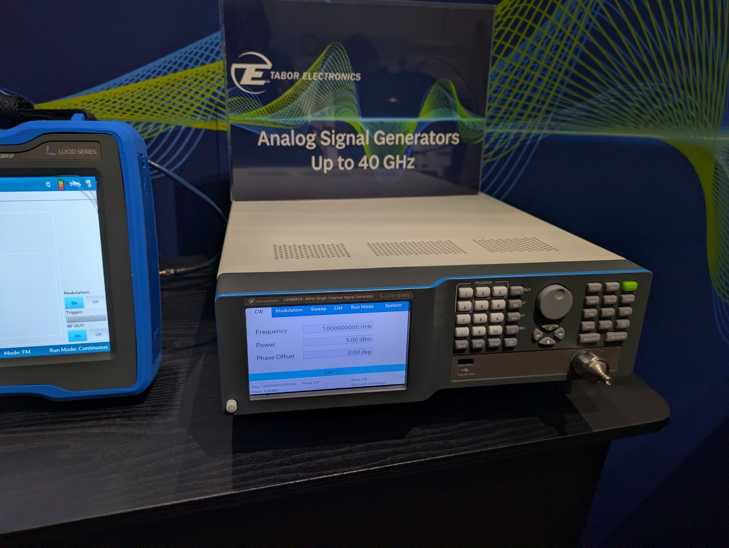 ### Rigol RSA7500 – neuer Spektrumanalysator in Prototypform Im Hause Rigol ist man – offensichtlich – in Sachen RF-Testgeräten auf den Geschmack
sauber zurücksetzt und dann synchron startet. Für PWM ist für den synchronen Start das Register PWM_BASE+EN zuständig. (Seite 1088) Für PIO ist für den synchronen Start das Register PIO[012]_BASE+CTRL zuständig. (Seite 939)
komplexer werden, braucht man manchmal etwas Platz. ``` set pins, 0 ; Beide AUS -> Totzeit (~40ns) nop ; nops fuer Totzeit nop ; nop nop ``` ``` set pins, 0 [4] ; Erst Befehl ausführen, dann n Zyklen anhalten (0…31) ```
without requiring tools. There is a compartment (22) on the back for sLoring soldering tips. The base plate on the compartment contains a S cleaning element (23) for cleaning the soldering tip. E E V L L 6-18 WD 1 (M) / WD 1000 (M) 4.2 Technical data WD 1 (M) / WD 1000 (M) Dimensions L x W x H (mm):
AT -2801FX Fast Ethernet PCMCIA Fiber Adapter Card A T-2801FX/xx-001 PC Interface Key Features 100BaseFX 32-bit Ethernet adapter PC card standard release 8.1 and 68 pin connector • 100Mbps Fiber port with SC or ST connector Mobile ConnectivityThrough Fiber Network Connector AlliedTelesis’ AT-2801FX PCMCIA
other physical characteristics may differ. The normal operating temperature should be between 0° and 40°C. Never use the instrument in a room with high humidity (>95 %) or at very low temperatures (condensation water!). Manufacturer Consort bvba Parklaan 36 Tel (+32)(14)41 12 79 B2300 Turnhout Fax (+32
Building C object esp-idf/wpa_supplicant/CMakeFiles/__idf_wpa_supplicant.dir/src/crypto/aes-gcm.c.obj [40/1714] Building C object esp-idf/wpa_supplicant/CMakeFiles/__idf_wpa_supplicant.dir/src/crypto/dh_groups.c.obj [41/1714] Building C object esp-idf/wpa_supplicant/CMakeFiles/__idf_wpa_supplicant.dir/src
All USB registers are 16 bit width but they must be accessed with 32 bit instructions. #define USB_BASE 0x40005C00 #define USB_EpRegs(x) (*(volatile uint32_t *)(0x40005C00 + 4*(x))) #define USB_EP0R (*(volatile uint32_t *)(0x40005C00)) #define USB_EP1R (*(volatile uint32_t *)(0x40005C04)) #define USB_EP2R
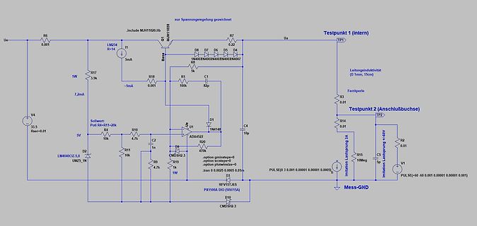
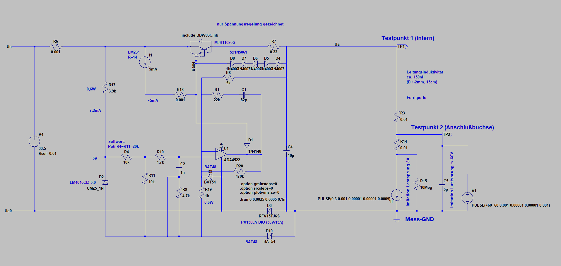
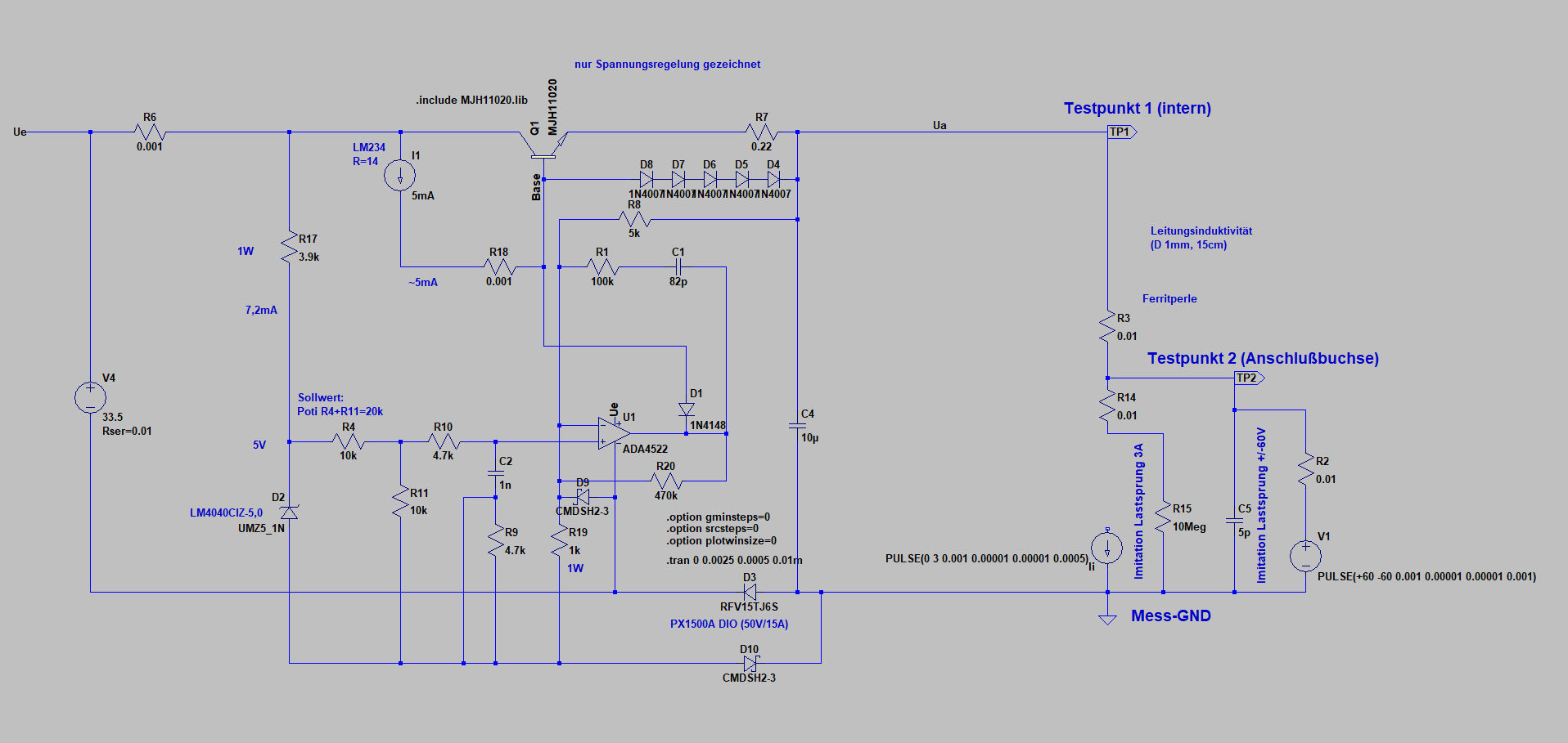
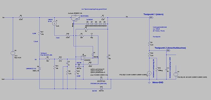
Rückkopplungen kann man dann auch besser optimieren. Zwischendurch ist mir ein einfacher Schaltregler für 40V/3A über den Weg gelaufen - könnte man ev. auch als Vorregler für Ue einsetzen.. Hallo, hat jemand von den Experten ein Ltspice Model für einen MJH11020G???
attribute functions. Weight: 1.2 g (typ.) Features ▯Display format (pin−selectable) Columns : 32, 40, 64, 80 Lines : 2, 4, 6, 8, 10, 12, 14, 16, 20, 24, 28, 32 The combination of number of columns and number of lines must not cause the frequency to exceed 5.5 MHz. (See Fig. 2) ▯Character font (pinselectable
Passage: [c] Because the digital PHY is integrated into the MCU, developers only need an external 10BASE-T1S PMD transceiver to implement a complete Single Pair Ethernet solution, reducing components and simplifying system design. When paired with NXP's TJF1410 10BASE-T1S Physical Medium Dependent (PMD
will provide a complete Single Pair Ethernet (SPE) solution optimized for IEEE 802.3cg-compliant 10BASE-T1S networks. [/c] Die offizielle Verfügbarwerdung ist für das vierte Quartal des Jahres geplant. Mit dem FRDM-MCXA577 soll es auch eine in der FRDM-Serie ansässige Evaluationsplatine geben. Eine
ansonsten verwende ich für alte wie neue Zellen gern vorsichtige Ladegrenzen, z.B. 1,55V und max. 40°C. Bei extrem hohen Innenwiederständen (so ab ca. 2000mOhm aufwärts) meldet das MC3000 "Battery so poor!" oder "Connection interrupted!" und mag dann nicht weiter machen, allerdings scheint in solchen
die denn dann richtig voll-laden oder an ihre max-Werte testen? Die Temp. sollte man eh nie über 40 Grad stellen, denn jedes Grad drüber schädigt den Akku mehr als nötig, die Spannung steht von Hause aus auf 1,65 V, denn die ist nicht der primäre Faktor beim Laden, die Vorsicht ist also allgemein für
unbedingt, es gab auch Ferraris mit Zählausgang. Aber digitale sollten inzwischen Standard sein (die nicht 40 Jahre geeicht halten sondern nur 10, kein Fortschritt).
the scale on its side to disassemble and mount the display unit. Unfasten the Allen screws on the base plate and remove the base plate. Remove the fastening screws. 1–16 Remove the screws on the retainer plate. Then set the scale back upright. Remove the screws on the base (7). Lay the support arm along with the base and the display unit on a table. Remove the plugs from the long side of the scale (insert them in the holes on the short side). Loosely attach the display unit with the support arm and base to the long
NetworkManager.service; enabled; preset: enabled) Active: active (running) since Mon 2026-08-03 21:40:36 CEST; 7min ago Invocation: b3713c24358845bdba251a6fc4323b8b Docs: man:NetworkManager(8) Main PID: 921 (NetworkManager) Tasks: 4 (limit: 4915) CPU: 527ms CGroup:
Cannot add port 'tty/ttyUSB0', unhandled port type Aug 03 21:42:30 chupi ModemManager[973]: <msg> [base-manager] modem for device '/sys/devices/platform/axi/1000120000.pcie/1f00300000.usb/xhci-hcd.1/usb3/3-1' successfully created Aug 03 21:42:30 chupi ModemManager[973]: <msg> [base-manager] running setup
Zur Zeit gibts beim Pollin Maxl das OWON LCD-Oszilloskop mit Multimeter, HDS242, 2-Kanal, 40 MHz für 111.- €
Temperaturbereich: -20 °C bis +40 °C (geeignet für Kühl- und Gefrierbereiche) Heute gibt es LED ab -40 Grad. https://de.benweilight.com/info/can-you-use-led-bulbs-in-fridge-78010027.html D.h. austauschen waere moeglich. Aber
. Æ Use the Y-axis tensioning keys to pre-tension the toothed belt. Æ Install the component table base plate, secure the fastening screws with loctite and assemble the component table guidance. Æ Secure the screws of the component table base plate with loctite. Æ Install the cutter and the empty-table
0xAA. This register is read/write. Memory Space Configuration Register Name Index Definition Memory base address 0x40 Read/write value indicating the selected memory base address bits[23:16] for bits[23:16] descriptor 0 memory descriptor 0. This is the Boot Prom Space. Memory base address 0x41 Read/write
supply 10) P2007: Y-Gain CH I at 5 mV/div 4) -6 Volt accuracy check 17) P2011: Y-Gain CH II at 5 mV/div 40) VR7003: Trace Rotation check 28) CV4001: 0.1 μs/div time base adjustment 41) RV4501: Component-Tester trace inclination 29) RV4004: 50 μs/div time base adjustment 42) RV4502: Calibrator Output 30) RV4003: 50 ms/div time base adjustment 34) RV4001: Trigger-Symmetry 40) VR7003: Trace Rotation Check YP Board CC Board 1 Before removing the YP board, check that the power cable 1 Before removing the CC board, check that the power
address and addressing mode of the exception or interruptfunction are defined bythe exception entry base address register mtvec. mtvec[31:2] defines the base address of the exception or interrupt function. mtvec[1:0] defines the addressing mode of the handler function, where mtvec[0] defines the entry
C The WDT time-out flag after: 1s F8 100 101X-0011-X C Time base clock output:8Hz, The WDT time-out flag after: 1/2s Time base clock output:16Hz, F16 100 101X-0100-X C The WDT time-out flag after: 1/4s Time base clock output:32Hz, F32 100 101X-0101-X C The WDT time-out
EC47650 ELECT 47UF/50V 8 C166,168,170,171,173,174,175,177 3 IC4580L IC NJM4580L 1 IC35 3 JK5031 XLR BASE 4 MIC1,2,3,4 3 JK6353-02-250 MIC BASE 19 J1~J19 3 LD-LG2040 GREEN LED 12 LED2,3,11,12,13,14,15,16,17,18,19,20 3 LDLT0311-41 RED LED 7 LED1,5,6,21,22,23,24 3 LDLY2040A YELLOW LED 5 LED4,7,8,9,10 C217,223,238,240,244,246,250,252,256,258,261,262
~ 32.4V OVER VOLTAGE Protection type : Shut down o/p voltage, re-power on to recover WORKINGTEMP. -40 ~ +55℃(no derating) ; +70℃@60%load by free air convection ; +70℃(no derating with external base plate) WORKINGHUMIDITY 5 ~ 95%RH non-condensing ENVIRONMENTSTORAGE TEMP., HUMIDITY -40 ~ +85℃, 10 ~ 95%
with Base series bases. To prevent damage to the device, do not stack Core2 v1.3 with any Base series expansion base. • When stacking Core2 v1.3 with M5 modules, you will need to remove the battery bottom
Protokolle: [c] ISO 14443A, ISO 14443B, FeliCa™, and ISO 15693 protocols [/c] ### Atomic Audio-3.5 Base Wer Sprachinformationen ein- oder ausgeben muss und dafür ein Audio-Frontend benötigt, wird von M5Stack mit der in der Abbildung gezeigten Atomic Audio-3.5 Base bedient.  4 AA 7-9 XOTSE40P12000 J Vis 4 mm x 12 mm (W) 4 AA 7-10 XFPSD50P10KS0 J Vis 4 mm x 1 0mm
MHz maximum internal clock frequency ■ Oscillator supervisor ■ Fully static operation HiQUAD64 ■ -40°C to + 150°C temperature range ■ User EPROM/OTP: 16 Kbytes ■ Data RAM: 256 bytes ■ 10-bit analog-to-digital converter ■ Data EEPROM: 128 bytes ■ Software watchdog for system integrity ■ 64 pin HiQUAD64
(dez.) und mehr steht Warum auch? Sind wir doch mal ehrlich: Windows 11 will mittlerweile gute 40 GB an Speicher; viele von den Dateien werden genau einmal geschrieben und liegen dann auf ewig dort herum. Gerade bei den hohen Datendichten und der damit einhergehenden extrem kleinen Magnetisierung
embedded servo information on the disk surface. Commonly, a servo writer uses a large, massive granite base to minimize the effects of vibration. The servo writer can also use precision fixtures to hold the target drive, a precision, laser-interferometer-based actuator arm positioning mecha nism to place

 Bild
Bild
 Bild
Bild