-
PDF
Datasheet-GEL-and-AGM-Batteries-DE.pdf
BAT212200084 22 12 181x77x167 5,8 400 Zyklen bei 80% Entladung 600 Zyklen bei 50% Entladung BAT412350084 38 12 197x165x170 12,5 1500 Zyklen bei 30% Entladung BAT412550084 60 12 229x138x227 20 280 80 BAT412600084 66 12 258x166x235 24 300 90 BAT412800084 90 12 350x167x183 27 400 130 BAT412101084 110 12 330x171x220 32 500 170 BAT412121084 130 12 410x176x227 38 550 200 BAT412151084 165 12 485x172x240 47 600 220 BAT412201084 220 12 522x238x240
-
PDF
118.pdf
4,1 400 Zyklen bei 80% Entladung BAT212200080 22 12 181x77x167 5,8 600 Zyklen bei 50% Entladung BAT412350080 38 12 197x165x170 12,5 1500 Zyklen bei 30% Entladung BAT412550080 60 12 229x138x227 20 450 90 BAT412600080 66 12 258x166x235 24 520 100 BAT412800080 90 12 350x167x183 27 600 145 BAT412101080 110 12 330x171x220 32 800 190 BAT412121080 130 12 410x176x227 38 1000 230 BAT412151080 165 12 485x172x240 47 1200 320 BAT412201080 220 12 522x238x240
in „Blei-Vlies Akku richtig laden“ · Analoge Elektronik und Schaltungstechnik ·
-
PDF
TJA1054A_3.pdf
CONDITIONS MIN. TYP. MAX. UNIT VCC supply voltage on piCCV 4.75 − 5.25 V V battery voltage on pin BAT no time limit −0.3 − +40 V BAT operating mode; note 1 5.0 − 27 V load dump − − 40 V BAT battery current on pin BAT sleep mode; CC = 0 V; − 30 50 A V = 12 V BAT VCANH CANH bus line voltage VCC = 0 to
-
PDF
gysmi_165_inverter.pdf
16W 1 9 1 9 470nF (50V) 470nF (50V) 64132 64132 D D Tr ETD29 Tr ETD29 M_24V_S M_24V_S TitlePCB GYSMI 165 GYS SA 134, bld des loges Size: A3 Number: 97022 RevisionInd2 53941Saint BERTHEVIN Date: 02/08/2005 Time: Sheet2 of 6 FRANCE File: O:\mma\GYSMI 165\Encoursde developpement\Ind2\PCB(fichiers PROTELuniquement
in „(S) Service manual Gysmi“ · Markt ·
-
Datei
Athlet_V1_4_32_4.ino
{ //display blinking led-bar for battery-status depending of battery voltage and charge-levels if (BAT>VBAT_CHG_LOW || toogle) digitalWrite(LED_LOW, HIGH); else digitalWrite(LED_LOW, LOW); if (BAT>VBAT_CHG_LOW && ( BAT>VBAT_CHG_MID || toogle )) digitalWrite(LED_MID, HIGH); else digitalWrite(LED_MID,
in „Bosch Athlet 25,2 V Akku 7 Stück Tauschen“ · Analoge Elektronik und Schaltungstechnik ·
-
PDF
Dali_Geraet_mit_sehr_niedrigem_Standby-Verbrauch.pdf
Nennstrom Lichtstrom bei 35°C Anzahl Verlustleistung Brennstelle n QTi DALI 2X35/49/80 DIM DULUX L 80 W 165.00 W 0.74 A 6000 lm 2 HE 35 W 74.00 W 0.34 A 3300 lm 2 HE 35 W XT 74.00 W 0.34 A 3300 lm 2 HO 45 W ES 101.00 W 0.45 A 4600 lm 2 HO 49 W 101.00 W 0.46 A 4300 lm 2 HO 73 W ES 165.00 W 0.72 A 6400 lm 2 __ HO 80 W 165.00 W 0.74 A 6150 lm 2 HO 80 W XT 165.00 W 0.74 A 6150 lm 2 29. November 2017, 16:36:21 © 2017, OSRAM GmbH. Alle Rechte vorbehalten. QTi DALI 2X35/49/80 DIM Seite 8 von 8
-
PDF
Siemens_CrossRef_1998.pdf
BAS125W BAS125 BAS125-07 BAS125-07W BAS125-04 BAS125-04W BAS125-05 BAS125-05W BAS125-06 BAS125-06W BAT14-098 BAT14-03W BAT15-098 BAT15-03W BAT17W BAT17 BAT17-04 BAT17-04W BAT17-05 BAT17-05W BAT17-06 BAT17-06W BAT16-046 BAT62-03W BAT62-02W BAT62 BAT62-07W BAT63-03W BAT63 BAT63-099R BAT85 BAT64-03W BAT64-02W BAT64 BAT64-07 BAT64-07W BAT64-04 BAT64-04W BAT64-05 BAT64-05W BAT64-06 BAT64-06W BAT65 BAT165 BAT68-03W BAT68 BAT68-07 BAT68W BAT68-07W BAT68-04 BAT68-04W BAT68-05 BAT68-05W BAT68-06 BAT68-06W BAV19 BAS19
in „1N4001und BC574C ==> SMD?“ · Analoge Elektronik und Schaltungstechnik ·
-
PDF
Siemens_CrossRef_1998.pdf
BAS125W BAS125 BAS125-07 BAS125-07W BAS125-04 BAS125-04W BAS125-05 BAS125-05W BAS125-06 BAS125-06W BAT14-098 BAT14-03W BAT15-098 BAT15-03W BAT17W BAT17 BAT17-04 BAT17-04W BAT17-05 BAT17-05W BAT17-06 BAT17-06W BAT16-046 BAT62-03W BAT62-02W BAT62 BAT62-07W BAT63-03W BAT63 BAT63-099R BAT85 BAT64-03W BAT64-02W BAT64 BAT64-07 BAT64-07W BAT64-04 BAT64-04W BAT64-05 BAT64-05W BAT64-06 BAT64-06W BAT65 BAT165 BAT68-03W BAT68 BAT68-07 BAT68W BAT68-07W BAT68-04 BAT68-04W BAT68-05 BAT68-05W BAT68-06 BAT68-06W BAV19 BAS19
in „Suche NPN Transistor Low Noise SMD“ · Mikrocontroller und Digitale Elektronik ·
-
PDF
Siemens_CrossRef_1998.pdf
BAS125W BAS125 BAS125-07 BAS125-07W BAS125-04 BAS125-04W BAS125-05 BAS125-05W BAS125-06 BAS125-06W BAT14-098 BAT14-03W BAT15-098 BAT15-03W BAT17W BAT17 BAT17-04 BAT17-04W BAT17-05 BAT17-05W BAT17-06 BAT17-06W BAT16-046 BAT62-03W BAT62-02W BAT62 BAT62-07W BAT63-03W BAT63 BAT63-099R BAT85 BAT64-03W BAT64-02W BAT64 BAT64-07 BAT64-07W BAT64-04 BAT64-04W BAT64-05 BAT64-05W BAT64-06 BAT64-06W BAT65 BAT165 BAT68-03W BAT68 BAT68-07 BAT68W BAT68-07W BAT68-04 BAT68-04W BAT68-05 BAT68-05W BAT68-06 BAT68-06W BAV19 BAS19
in „SMD - Transistoren“ · Analoge Elektronik und Schaltungstechnik ·
-
PDF
Siemens_CrossRef_1998.pdf
BAS125W BAS125 BAS125-07 BAS125-07W BAS125-04 BAS125-04W BAS125-05 BAS125-05W BAS125-06 BAS125-06W BAT14-098 BAT14-03W BAT15-098 BAT15-03W BAT17W BAT17 BAT17-04 BAT17-04W BAT17-05 BAT17-05W BAT17-06 BAT17-06W BAT16-046 BAT62-03W BAT62-02W BAT62 BAT62-07W BAT63-03W BAT63 BAT63-099R BAT85 BAT64-03W BAT64-02W BAT64 BAT64-07 BAT64-07W BAT64-04 BAT64-04W BAT64-05 BAT64-05W BAT64-06 BAT64-06W BAT65 BAT165 BAT68-03W BAT68 BAT68-07 BAT68W BAT68-07W BAT68-04 BAT68-04W BAT68-05 BAT68-05W BAT68-06 BAT68-06W BAV19 BAS19
in „BC337-40 in Pspice“ · Analoge Elektronik und Schaltungstechnik ·
-
PDF
Siemens_CrossRef_1998.pdf
BAS125W BAS125 BAS125-07 BAS125-07W BAS125-04 BAS125-04W BAS125-05 BAS125-05W BAS125-06 BAS125-06W BAT14-098 BAT14-03W BAT15-098 BAT15-03W BAT17W BAT17 BAT17-04 BAT17-04W BAT17-05 BAT17-05W BAT17-06 BAT17-06W BAT16-046 BAT62-03W BAT62-02W BAT62 BAT62-07W BAT63-03W BAT63 BAT63-099R BAT85 BAT64-03W BAT64-02W BAT64 BAT64-07 BAT64-07W BAT64-04 BAT64-04W BAT64-05 BAT64-05W BAT64-06 BAT64-06W BAT65 BAT165 BAT68-03W BAT68 BAT68-07 BAT68W BAT68-07W BAT68-04 BAT68-04W BAT68-05 BAT68-05W BAT68-06 BAT68-06W BAV19 BAS19
in „SMD-Vergleichstypen von Transistoren“ · Mikrocontroller und Digitale Elektronik ·
-
PDF
LT1513_data_en.pdf
specificationscarefullybeforemakingafinalchoiceforthe (I ) (R )(V +V )(V ) switching diode. Be aware that diode manufacturers want PSW = CHRG SW BAT IN BAT (VIN2 to specify a maximum leakage current that is ten times higherthanthetypicalleakage.Itisverydifficulttogetthem R =OutputswitchONresistance tospecifyalowleakagecurrentinhighvolumeproduction
in „6V Bleigel-Akku mit 12V/230mA Solarpanel laden“ · Mikrocontroller und Digitale Elektronik ·
-
PDF
HP_MSA-0520.pdf
. 2. Referenced from 0.1 GHz Gain (P). 6-359 MSA-0520 Typical Scattering Parameters (T = 25°C, I = 165 mA) A d Freq. S11 S21 S12 S 22 MHz Mag Ang dB Mag Ang dB Mag Ang Mag Ang k 5 .57 –38 14.4 5.25 165 –19.4 .107 38 .67 –35 0.57 25 .25 –90 10.7 3.42 160 –14.9 .180 17 .29 –81 0.93 50 .15 –111 9.5 2.97
in „[S] RF-Transistor AT-64020 oder einen adäquaten Ersatz“ · Markt ·
-
PDF
SL2470C_SL2450C_Bedienungsanleitung.pdf
Starthilfe “1. Wichtige Sicherheitshin- weise“ beachten! Bei SL 2450 C: SL 2450 C 6 V max. 110 A (arithm.) 165 A (effekt.) Kombischalter (4) bei richtiger Spannung 12 V max. 110 A (arithm.) 165 A (effekt.) auf Symbol-Lastwagen stellen. Schaltuhr 24 V max. 100 A (arithm.) 150 A (effekt.) einschalten. Fahrzeug
in „Trafo Draht 1,28mm durch 1,32mm ersetzbar?“ · HF, Funk und Felder ·
-
PDF
ec0e6f47-c1bb-4675-a7a3-18d434f2b127.pdf
er service centres structions for only. charging and never charge the Special safety battery or the bat- directions for bat- tery-powered tool tery-operated tools outside the temper- ature range stated • Ensure that the in the operating in- device is switched 41 GB MT off before inserting • Allow a hot
in „Makita 18V Akku Kapazitätsmessung“ · Mechanik, Gehäuse, Werkzeug ·
-
PDF
TJA1055_4.pdf
low power modes at VTXD = VCC Tamb = −40 °C to +85 °C 0 0 5 A Tamb = +85 °C to +125 °C 0 0 25 A V BAT battery supply voltage no time limit −0.3 - +40 V operating mode 5.0 - 40 V load dump - - 58 V I battery supply current sleep mode at - 25 40 A BAT VRTL = VWAKE = VINH= V BAT = 14 V Tamb = −40 °C to +125 °C low power mode at VRTL = VWAKE = VINH= V BAT Tamb = −40 °C to +125 °C VBAT = 5 V to 8 V 10 - 100 A VBAT = 8 V to 40 V 10 - 75 A normal operating mode at - 150 220 A VRTL = VWAKE = VINH= V BAT= 5 V to 40 V V pof(BAT) power-on flag voltage on low
in „TJA1055T VBAT und VCC - CAN Bus“ · Mikrocontroller und Digitale Elektronik ·
-
Datei
spicemodels_schottky_diodes.txt
BV=30.0 IBV=500n + CJO=8.88p M=0.333 N=3.51 TT=7.20n ) *SRC=BAT43W;DI_BAT43W;Diodes;Si; 30.0V 0.200A 5.00ns Diodes Inc Schottky Diode .MODEL DI_BAT43W D ( IS=87.5u RS=18.1m BV=30.0 IBV=500n + CJO=8.88p M=0.333 N=3.51 TT=7.20n ) *SRC=BAT43WS;DI_BAT43WS;Diodes;Si;
in „ltSpice Schottky's nicht auffindbar“ · Analoge Elektronik und Schaltungstechnik ·
-
PDF
nacrt_main_board_rev10a_coulomb.pdf
L4 8 C46 D45=L4 8 C47 D4 8 C45 D44=L4 D D R196 155 832HA-1A-F-C 230V-N 22uF 22uF MMSZ5248 ACPL-T350 BAT54 ACPL-T350 BAT54 ACPL-T350 820nF BAT54 C32 ACPL-T350 8,2uF BAT54 C34 ACPL-T350 8,2uF BAT54 665K Ohm 12 V relay C122 R10 50V 5 50V 18V U3 C37 SOT-23 U1 C1 SOT-23 U4 SOT-23 U2 L4,SOT-23 U12 SOT-23 Q31
in „SUCHE Transistor KGF75N65KDF“ · Analoge Elektronik und Schaltungstechnik ·
-
 Bild
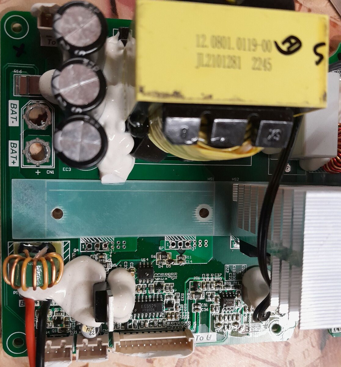
Nahaufnahme einer Leiterplatte mit Transformator und Kondensatoren
To BAT- BAT+ EC3 CN1 HS1 HS2 12.0801.0119-00 JL2101281 2245 U14 R6 R11 R4 DS C14 R22 R23 R25 R26 R27 R28 R29 R30 R31 R32 R33 R34 R35 R36 R37 R38 R39 R40 R41 R42 R43 R44 R45 R46 R47 R48 R49 R50 R51 R52 R53
in „PDP8974 Ersatz gesucht“ · Analoge Elektronik und Schaltungstechnik · · Platinenfotos
-
PDF
TJA1020.pdf
VBAT = 7.3 to 27 V 0.4V BAT − 0.6V BAT V voltage Vcntr(rx) receiver centre voltage VBAT = 7.3 to 27 V 0.475V BAT 0.5V BAT 0.525V BAT V V receiver threshold V = 7.3 to 27 V 0.145V 0.16V 0.175V V thr(hys) BAT BAT BAT BAT hysteresis
in „[S] MCP2004 LIN Tranceiver oder andere gesucht“ · Markt ·
-
PDF
33963.pdf
Alogic0iswrittenbybringingtheV pinlowforatleast LSB to MSB. To commit the data to the nonvolatile BAT 60 s, but not more than 120 s. A logic 1 is written by memory the V BAT pin is brought to 12V, witCCVat 8V, bringing the BAT pin low for at least 1 s, but not more for at least 250 ms. When VBAT is
in „[V] 2St Dallas DS1633 Ladechip TO220 3 Pin für“ · Markt ·
-
PDF
mini_edison_breakout_hvm_8_26.pdf
V_SYS U1 C6 2 C8 10uF 13 11 0.1uF 20% . IN OUT2 10 6.3V 1 C5 10uF R116 20% . J1 6.3V 1 2 1 TS 10K BAT1 2 J2 5% BAT2 3 1 2 6 EN1 . 5 EN2 DS3 V_SYS R114 R5 1.62K 12 ILIM CHRG 9 1 2 3 2 576 15 ITERM PGOOD 7 GREEN Q2 R6 16 . .1% R4 1K 1 BSS138 0R ISET B NO STUFF 14 8 B 1 TMR VSS NO STUFF 2 R72 4 17 2K CE
in „Intel Edison Breakout Board“ · Mikrocontroller und Digitale Elektronik ·
-
PDF
LC-R123R4PG.pdf
0.312 0.170 10.8V 11.8 10.1 7.41 5.90 5.19 3.97 2.88 2.27 1.51 1.13 0.897 0.708 0.567 0.472 0.307 0.165 All mentioned values are average values 1 * This battery is also available with a flame-retardant battery case resin (UL94 V-0): LC-V123R4PG. 52 INDIVIDUALDATASHEETS LC-R123R4PG* 1 CHARGINGMETHOD(25
in „Autoradio mit externem Netzteil +Pufferakku sowie ladegerät für Akku.“ · Analoge Elektronik und Schaltungstechnik ·
-
PDF
SW6007.pdf
超过此范围的电压电流及温度等条件可能导致器件永久损坏。 7. 推荐参数 Parameters Symbol MIN Typical MAX UNIT 输入电压 VBUSB/VBUSC 4.5 5.5 V 电池电压 BAT 2.8 4.5 V Mode: iSW_Release_DS066_v1.0 www.ismartware.com 第 5 页 共 19 页 珠海智融科技有限公司 ZHUHAI ISMARTWARE TECHNOLOGY CO., LTD. 8. 电气特性 (V IN5V, V BAT 3.7V, A = 25°C除特别说明。 ) Parameters Symbol Test Conditions
in „I2C: Li/ion Mobile Power Shield SW6007<->SW6115“ · Mikrocontroller und Digitale Elektronik ·
-
PDF
253499-da-01-en-AKKU_BLEI_12V_12_AH.pdf
organization does to ensure that its products or services (V) (Ah) of origin LC-X1224PG/APG 12 24 165 125 175 179.5/175 9.0 84 G198049 VdS N° satisfy the customer’s quality requirements and comply with 1 any regulations applicable to those products or services. LC-X1228P/AP * 12 28 165 125 175 179.5/175 11.0 86 – LC-R121R3PG 12 1,3 G196049 China LC-X1238PG/APG 12 38 197 165 175 180/175 13.0 88 G100002 ISO 14000 is primarily concerned with “environmental man- LC-R122R2PG 12 2,2 G188151 China LC-X1242P/AP *1 12 42 197 165 175 180/175 16.0 90 – agement”. In plain language
in „[v] Zyklenfeste 12v 144Wh Akkus Panasonic 12 V 12 Ah LC-RA1212PG1 Blei-Vlies (AGM)“ · Markt ·
-
PDF
TJA1041.pdf
UVNOM is set again. BUS FAILURE FLAG The bus failure flag is set if the transceiver detects a bus UV BAT FLAG line short-circuit condition tBAT, VCC or GND during four consecutive dominant-recessive cycles on pin TXD, when UV BAT is the VBAT undervoltage detection flag. The flag is set when the voltage on pin V BAT drops below V BAT(stb) trying to drive the bus lines dominant. In normal mode the When UV is set, the transceiver will try to enter standbybus failure flag can be made available on pin ERR. The BAT
in „I2C vs CAN vs Ethernet“ · Mikrocontroller und Digitale Elektronik ·
-
PDF
4088fb.pdf
Efficiency Battery Charger/USB Power Manager SystemLoad (P OUT BUS ) 100 WALL 3.3µH 90 80 USB V SW V SYSTEM BAT = 4.2V BUS OUT LOAD ) 70 10µF D0 Y 60 D1 GATE N 50 BAT = 3.3V D2 LTC4088 BAT I CHRG F 40 3.3V LDO3V3 10µF E 30 CLPROG PROG C/X GND NTC 20 VBUS= 5V 1µF 8.2Ω Li-Ion 10 BAT= 0mA 0.1µF 2.94k 499Ω 0 10x
in „[EAGLE Anfänger] Package finden oder herstellen“ · Platinen ·
-
PDF
ISL9301_fn6435.pdf
POWER-ON RESET Rising POR Threshold VPOR V = 3.0V, use PPR to indicate the comparator 3.3 3.9 4.3 V BAT Falling POR Threshold VPOR output. 3.1 3.6 4.15 V VOUT-BAT OFFSET VOLTAGE Rising Edge V OS V = 4.0V, use CHG pin to indicate the comparator - 110 250 mV BAT Falling Edge V OS output (Note 3) 10 100
in „Handyakku (3.6V) laden per LadeIC (4,2V)“ · Mikrocontroller und Digitale Elektronik ·
-
PDF
asus-p701-unlocked.pdf
T132 150Ohm/100Mhz change from DIP to SMD 1 TPC26T T133 TPC26T T134 GND 1 TPC26T T135 1 DCIN_GND C C BAT IN BAT 1 TPC26T T136 1 TPC26T T137 BATT_CON 1 TPC26T T138 10 1 TPC26T T139 P_GND1 L33 120Ohm/100Mhz 1 1 1 2 BAT_IN# [42] 2 2 3 3 4 4 L29 1 2 120Ohm/100Mhz BAT_ID [42] 5 5 6 6 L31 1 2 120Ohm/100Mhz BAT_TS
-
PDF
bq51051B.pdf
cycle 120 Ω ILIM-SHORT Monitored for BAT> 100 mA power to reset tDGL-Short Deglitch time transition froLIMshort toBAT disable 1 ms I LIM-SHORT,OKenables the ILIMshort comparator when I : 0 → 200 mA 110 145 165 mA LIM_SC BAT is greater than
in „BQ51051B Beschaltung Widerstand Ros“ · Mikrocontroller und Digitale Elektronik ·
-
PDF
Driver_3.pdf
2 C4 3 IN OUT 6 D1 4 GND 3 100nF 4 NC OUT 5 R4 5 VCC GND GND 5 NC RL 4 0 Header 5 IXDN609SI Diode BAT165 HFBR-25X1ETZ 12V_prim -12V_Sek -12V_Sek GND_prim Title D D Size Number Revision A4 Date: 14.03.2016 Sheet of File: C:\Users\..\Driver_3.SchDoc Drawn By: 1 2 3 4
in „Maximale Verlustleistung eines FET/IGBT Treibers -> IXDN609“ · Analoge Elektronik und Schaltungstechnik ·
-
 Bild
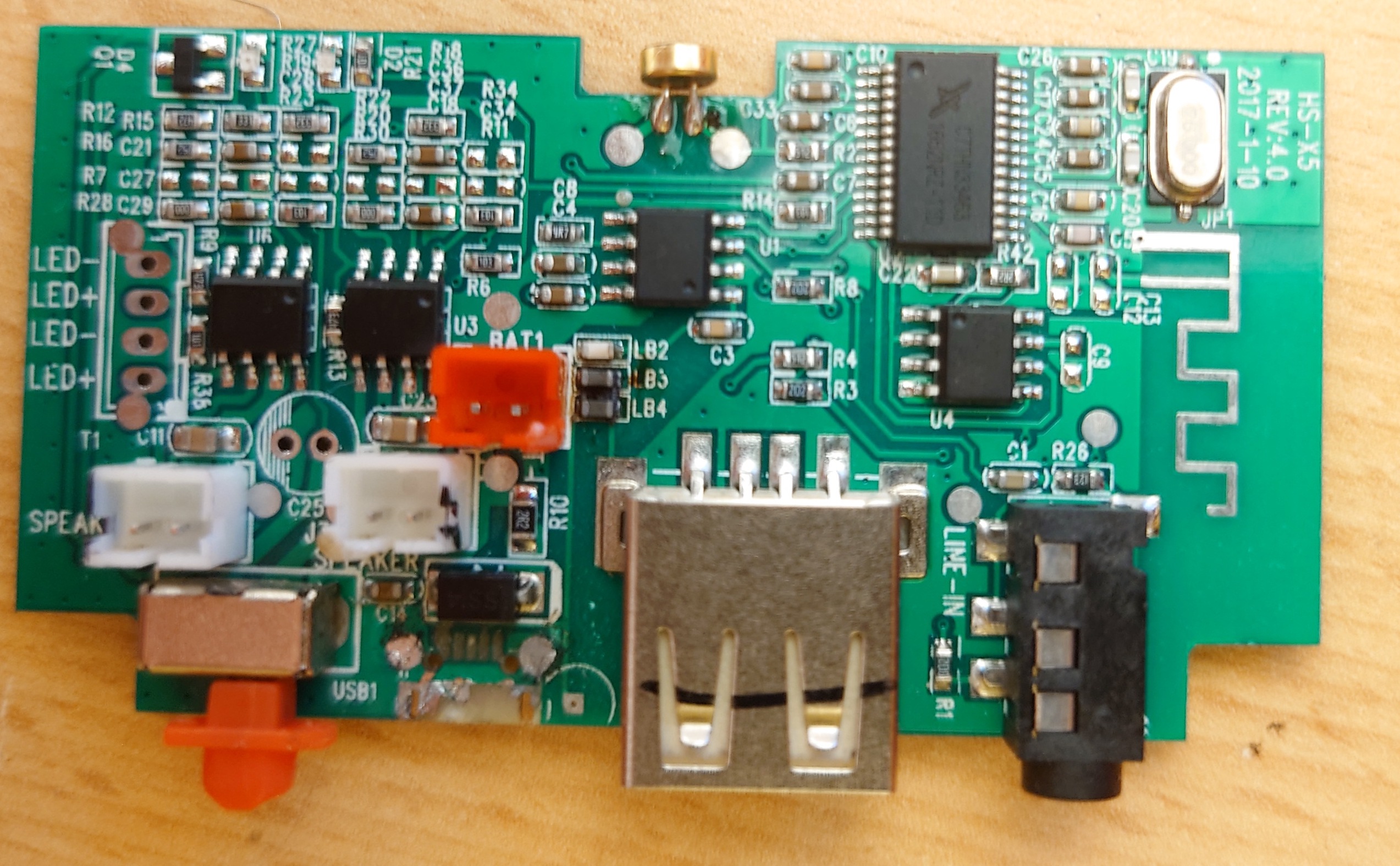
Leiterplatte mit USB, Audio-Anschlüssen und integrierten ICs
R12 R15 D4 C21 R16 R7 C27 R28 C29 U1R R13 U3 U6 BAT1 LB2 LB4 C3 R4 R3 U4 C1 R26 C9 C10 C20 C25 C26 C27 C28 C29 C30 C31 C32 C33 C34 C35 C36 C37 C38 C39 C40 C41 C42 C43 C44 C45 C46 C47 C48 C49 C50 C51 C52 C53 C54 C55 C56 C57 C58 C59 C60 C61 C62 C63 C64
in „Micro USB Ladebuchse, Kontakte abgerissen - Wo anlöten?“ · Platinen · · Platinenfotos
-
PDF
SSD1306B_1.1.pdf
Operating Voltage - 6 - 15 V V DD Logic Supply Voltage - 1.65 - 3.3 V Charge Pump Regulator Supply V BAT Voltage - 2.2 - 4.2 V V BAT= 2.2V~4.2V, 6V mode 5.5 6 - V Maximum output loading = 4mA V BAT= 3.0V~4.2V, 7.5V mode Charge Charge Pump Output Voltage Maximum output loading = 8mA 7 7.5 - V Pump V CC ITO resistance <3ohm for charge pump related pins(1) V BAT= 3.6V~4.2V, 8.5V mode 8 8.5 - V Maximum output loading = 12mA V BAT= 3.8V~4.2V, 9V mode Maximum output loading = 12mA 8.5 9 - V V OH High Logic Output Level IOUT= 100uA, 3.3MHz 0.9 x VDD - - V V OL
in „OLED zeigt nur wirre Pixel am I2C“ · Mikrocontroller und Digitale Elektronik ·
-
PDF
MCP73837.pdf
1 MCP73837/8 Package Types MCP73837/8 MCP73837/8 10-Lead DFN 3 mm x 3 mm 10-Lead MSOP V VAC 1 10 V BAT V AC 1 10 BAT VUSB 2 9 THERM VUSB 2 9 THERM STAT1 3 8 PG (TE) STAT1 3 8 PG (TE) STAT2 4 7 PROG2 STAT2 4 7 PROG2 V SS 5 6 PROG1 V SS 5 6 PROG1 Typical Applications MCP73837 Typical Application Ac-dc
in „Verständnissfrage - MCP73837“ · Mikrocontroller und Digitale Elektronik ·
-
PDF
MC_product_selection_AN.pdf
CHARGING LI-ION BATTERIES Charging in this manner replenishes a deeply depleted battery in roughly 165 minutes. Advanced chargers Unlike NiMH, the preferred charge algorithm for Lith- employ additional safety features. For example, charge ium-Ion / Lithium-Ion Polymer batteries is a CC-CV is suspended
in „Hackbarer(?) 21 EUR Quadcopter“ · Mikrocontroller und Digitale Elektronik ·
-
PDF
LED_Display_driver_chip_SSD1306_DataSheet.pdf
, etc. 2 FEATURES • Resolution: 128 x 64 dot matrix panel • Power supply o V DD = 1.65V to 3.3V, < BAT for IC logic o V BAT= 3.3V to 4.2V for charge pump regulator circuit o V CC = 7V to 15V for Panel driving • For matrix display o Segment maximum source current: 100uA o Common maximum sink current:
in „Spannungsversorgung Arduino läuft nicht über Vin oder 5V-Pin“ · Mikrocontroller und Digitale Elektronik ·
-
PDF
LED_Display_driver_chip_SSD1306_DataSheet.pdf
, etc. 2 FEATURES • Resolution: 128 x 64 dot matrix panel • Power supply o V DD = 1.65V to 3.3V, < BAT for IC logic o V BAT= 3.3V to 4.2V for charge pump regulator circuit o V CC = 7V to 15V for Panel driving • For matrix display o Segment maximum source current: 100uA o Common maximum sink current:
in „SSD1306/1309 Library zum Darstellen von Text auf OLED Displays“ · Projekte & Code ·
-
PDF
SSD1306.pdf
, etc. 2 FEATURES • Resolution: 128 x 64 dot matrix panel • Power supply o V DD = 1.65V to 3.3V, < BAT for IC logic o V BAT= 3.3V to 4.2V for charge pump regulator circuit o V CC = 7V to 15V for Panel driving • For matrix display o Segment maximum source current: 100uA o Common maximum sink current:
in „SH1106 Init-Sequenz“ · Mikrocontroller und Digitale Elektronik ·
-
PDF
Solomon_Systech_LED_Display_driver_chip_SSD1306.pdf
, etc. 2 FEATURES • Resolution: 128 x 64 dot matrix panel • Power supply o V DD = 1.65V to 3.3V, < BAT for IC logic o V BAT= 3.3V to 4.2V for charge pump regulator circuit o V CC = 7V to 15V for Panel driving • For matrix display o Segment maximum source current: 100uA o Common maximum sink current:
in „Mit Wire.h über I2C auf LCD-Display 1602 zugreifen“ · Mikrocontroller und Digitale Elektronik ·
-
PDF
Solomon_Systech_LED_Display_driver_chip_SSD1306.pdf
, etc. 2 FEATURES • Resolution: 128 x 64 dot matrix panel • Power supply o V DD = 1.65V to 3.3V, < BAT for IC logic o V BAT= 3.3V to 4.2V for charge pump regulator circuit o V CC = 7V to 15V for Panel driving • For matrix display o Segment maximum source current: 100uA o Common maximum sink current:
in „SSD1306/1309 Library zum Darstellen von Text auf OLED Displays“ · Projekte & Code ·
-
PDF
bq76940.pdf
Absolute Maximum Ratings Over-operating free-air temperature range (unless otherwise noted) MIN MAX UNIT (BAT–VSS) bq76920 V Supply voltage (BAT–VC5x), (VC5x–VSS) bq76930 –0.3 36 V BAT (BAT–VC10x), (VC10x–VC5x), (VC5x–VSS) bq76940 (VCn–VSS) where n = 1..5 bq76920 (VCn–VSS) where n = 1..5, (VCn-VC5x) where n
in „Schaltung für aktiven 3s Balancer gesucht“ · Analoge Elektronik und Schaltungstechnik ·
-
PDF
2006111335_Texas-Instruments-BQ7692003PWR_C601650.pdf
Absolute Maximum Ratings Over-operating free-air temperature range (unless otherwise noted) MIN MAX UNIT (BAT–VSS) bq76920 V Supply voltage (BAT–VC5x), (VC5x–VSS) bq76930 –0.3 36 V BAT (BAT–VC10x), (VC10x–VC5x), (VC5x–VSS) bq76940 (VCn–VSS) where n = 1..5 bq76920 (VCn–VSS) where n = 1..5, (VCn-VC5x) where n
in „bq76940 balancing“ · Mikrocontroller und Digitale Elektronik ·
-
PDF
CIII_Schematic.pdf
42 GND GND 156 C15 C14 C11 C9 C33 C34 C35 C36 CLK8, DIFFCLK_5n 209 77 VCCIO3 VCCINT 140 48 GND GND 165 178 VCCA2 GNDA2 179 0.1u 0.1u 0.1u 0.1u 0.1u 0.1u 0.1u 0.1u CycloneIII serial FPGA EP3C16Q240 is pin to pin compatible with EP3C25Q240 . CLK9, DIFFCLK_5p 210 VCCINT 163 54 GND GND 172 180 VCCD_PLL2
in „fragen zu User/KOnfigurationsmodus von Cyclon“ · FPGA, VHDL & Co. ·
-
Datei
bat_sensor_0x0d_analysis.html
162.47, 162.68, 162.89, 163.1, 163.3, 163.51, 163.72, 163.93, 164.14, 164.34, 164.55, 164.76, 164.97, 165.18, 165.39, 165.59, 165.8, 166.01, 166.22, 166.43, 166.63, 166.84, 167.05, 167.26, 167.47, 167.67, 167.88, 168.09, 168.3, 168.51, 168.71, 168.92, 169.13, 169.34, 169.55, 169.75, 169.96, 170.17, 170.38
in „Reverse Engineering eines LIN Bus“ · Mikrocontroller und Digitale Elektronik ·
-
PDF
SMD_Catalog.pdf
DC-4GHz MMIC amp 21 dB gain 55D BAT15-055D Sie CY SOT173 8GHz schottky dual 55s BAT17-05 Sie A SOT23 dual ca BAT17 55s BAT17-05W Sie A SOT323 dual ca BAT17 BAT17-06 Sie B SOT23 dual cc BAT17 56s 56s BAT17-06W Sie B SOT323 dual cc BAT17
in „Hilfe bei Bauteilsuche für Mainboard“ · PC Hard- und Software ·
-
PDF
teXet_TF-127_Service_manual.pdf
the total of the supply current of the ISL1BAT )I BAT BACKUP BATAVG LKG BAT2 BAT1 plus the leakage current of the capacitor and the dioLKG.I (EQ. 7) In these calculationsLKG is assumed to be extremely small and will be ignored. If an application
in „Photo-Rahmen als Farbdisplay“ · Mikrocontroller und Digitale Elektronik ·
-
PDF
ST_70-780_Service_Manual.pdf
in-/output, SBAS input, RGB input Alimentation / Mains Stage Tension secteur (Plage de variation) 165…265V 165…265V 165…265V 165…265V 165…265V Mains voltage (variable) Fréquence Mains frequency 50 / 60Hz 50 / 60Hz 50 / 60Hz 50 / 60Hz 50 / 60Hz Consommation normale Power consumption env. 70W env. 75W
in „PAL-Röhren TV auf NTSC umbauen“ · Analoge Elektronik und Schaltungstechnik ·
-
PDF
Grundig_ST70-780_text_Service-Manual.pdf
input SBAS input e n Netzteil / Mains Stage r Netzspannung (Regelber.) T Mains voltage (variable) 165…265V 165…265V 165…265V 165…265V 165…265V 165…265V 165…265V 165…265V i / Netzfrequenz G Mains frequency 50 / 60Hz 50 / 60Hz 50 / 60Hz 50 / 60Hz 50 / 60Hz 50 / 60Hz 50 / 60Hz 50 / 60Hz n r Leistungsaufnahme
in „PAL-Röhren TV auf NTSC umbauen“ · Analoge Elektronik und Schaltungstechnik ·
-
PDF
MB1137.pdf
LD_BICOLOR_CMS D4 JP2 CN2 VIN_5V P0D401 P0D402 P0JP201 P0JP20 P0R1802 [N/AP0R1801 P0CN201 P0CN202 +3V3_ST_LINK BAT60JFILM D3 P0D301 P0D302 Not Fitted E5V USB ST-LINK U5V BAT60JFILM PWR D5 U3 LD3985M33R +3V3_ST_LINK CN1 Diff Pair 90ohm P0U301 50U305 U5V P0D501 P0D502 Vin Vout P0CN111 i 0 0 VBUS P0CN102 1 C e DM 2 STLI K_USB_DMNK0USB0DM BAT60JFILM P P0U303 INH P c P0C3103 STLI K_USB_DPNK0USB0DP 1 C14 GN2 BYP4SS 2 C9 t DP 1 3 3 9 p P04N104 0 U5V 1uF_X0R_0603 0 P P 0 P 1uF_X5R_0003 c ID P0CN105 R i 2 P C 2 4 C C e GND 5 P 9 +3V3_ST_LINK
in „Suche Mikrocontroller mit 16Bit ADCs und DACs“ · Mikrocontroller und Digitale Elektronik ·
-
PDF
Sanyo_CADNICA.pdf
1/AA N-270AA 1.2 270 1.0 27 14-16 81 4-6 1.6 14.5~g5 30.0 ~~ 14 2/3AA N-500AA 1.2 550 1.0 55 14-16 165 4-6 1.6 24 AA 14.2~g5 50.0 ~~ N-550AA 1.2 550 1.0 55 14-16 165 4-6 1.6 14.2~g5 50.0 ~~ 24 AA 1/A N-160A 1.2 160 1.0 16 14-16 48 4-6 1.6 17.0~g5 17.0 ~~ 11 N-450A 1.2 450 1.0 45 14-16 135 4-6 1.6 17.0
in „Was für ein Bauteile ist das“ · Mikrocontroller und Digitale Elektronik ·