maximal erlaubte Ladeendspannung eingestellt, an dem Punkt wird das Ding zum Konstantspannungsnetzteil. CC/CV Ladefunktion gratis und das Ding kann auf keinen Fall die Akkus überladen (noch bevor das BMS das verhindert), völlig egal was der µC oder dessen Software macht. Der µC kümmert sich gewissermaßen
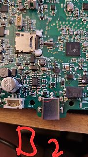
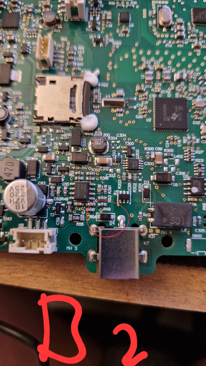
Die Toniebox ist auch so ein Markt. CC3200, CC3235 und ESP32 laut 37c3
geblendet. Schön wär's, wenn ich mir einen Lambo leisten könnte! Nein, es ist ein 22 Jahre alter 206CC! Zugegeben, 5cm niedriger als ein normales Auto, aber trotz meines Alters schaffe ich es noch bequem heraus. Was mir dabei hilft, sind die breiten Türen eines Zweisitzers. Da brauche ich keinen SUFF,
Helmut -. schrieb im Beitrag #8016774: > Nein, es ist ein > 22 Jahre alter 206CC! Ist der 206CC nicht dieses kleine Hausfrauen Cabrio? Wo man nichts in den Kofferraum bekommt, berghoch Angst haben muss auf der Autobahn ein LKW zu überholen weil der für sein Gewicht mit der Dachkonstruktion
DIGITAL _ 1 I U +3.3DSP T IC67 : TC7WH32FK A 0 5 8 1 S Dual 2-input OR gate 0 L 5 / 2 0 for EMC V CC 1Y 2B 2A 2 DIR_N_RST 0 . 6 V+ IC67 1 +5A DIR_N_RST 6 3 0 C K no_use no_us e DIR1_N_INT +3.3DSP 6 4 R 3 DIR DIGITAL OUT IC67 B no_use 8 7 6 5 DIR1_N_INT 100mA / 0 4 V- DIR1_N_CS DGND BKP1005HS680-T 1
oscilloscope that acquires data using an Arduino or a Parallax (more platforms to come). (Lizenz: CC-BY-NC-SA 3.0; Windows and Linux (needs mono)) Oscope 2100 Linux software für Hantek DSO-2100. OpenHantek Linux Software für Hantek (Voltcraft/Darkwire/Protek/Acetech) DSO-2090. Digital Soda DSO-2250
einige LED-Netzteile haben einen CC-Modus. Die max. Spannung bei CV ist oftmals nicht so genau spezifiziert. Kommt dann auch darauf an, welche Spannung das vorhandene BMS verträgt. Von Meanwell, das HVGC-1000A geht in diese Richtung.
Compressors For DCVoltage R134a | R404A | R507 | R290 | R600a 12/24/48 The widest range compressorsurrent cc.danfoss.com Hermetic Compressors for DC Voltage Part 1 BD Compressors - Product range Part I BD Compressors – Product Range............................................................................
0.625 0.3125 0.156 0.078 0.039 Update rate [Hz] 0.78 1.56 3.125 6.25 12.5 25 50 100 200 400 800 1600 3200 The sensortime is synchronized with the data capturing in the data register and the FIFO. Between the data sampling and the data capturing there is a delay which depends on the settings in the Register
Einfach Super Hfe Transistoren wie zB sowas, bzw. komplementaerer, 2SC3622 - 2SC3624 (hfe 1000-3200), ggf parallel.
Hexenwerk ist das nun wahrlich nicht. Leute denen das zu klein ist, sollten vielleicht besser bei der E88CC bleiben. Das "allerdings SMD" hat inzwischen sooo einen langen Bart ...
Cadex C5100 Battery Tester ISO 78,42 8015 CAT 237-5130 Digitalmultimeter ohne IR ISO 56,70 8375 Catu CC-575-10/30-B Mittelspanungsprüfer ISO 82,04 7918 Catu CC-575-5/15-B Mittelspanungsprüfer ISO 82,04 7919 Catu CL-10 VD Mittelspanungsprüfer ISO 82,04 7917 Chauvin Arnoux 100 kOhm Widerstandsdekade ISO
. Typ.a Max. Unit Test Conditions Fig. Note Current Transfer Ratio CTR 800 3500 25k % IF=40μA,V CC = V O 0.4V 3, 4 b 4.5V 600 3000 8k IF=0.5mA, V CC = 4.5V 700 3200 25k IF= 40 μA 500 2700 8k IF= 0.5 mA Logic Low Output Voltage VOL — 0.06 0.4 V IF= 40 μA, O = 280 μA 1, 2 — 0.04 0.4 I = 0.5mA,I = 2.5mA F O Logic High Output Current I — 0.01 5 μA V = V = 3Vto7V, I = 0 mA OH O CC F — 0.02 80 V O V CC= 18V, F = 0 mA Logic Low Supply Current CCL 4701/070A — 0.02 0.2 mA IF= 40μA V O Open — 0.1 1 IF= 0.5 mA 4731/073A — 0.04 0.4 IF = 40 μA — 0.2 2.0 I = 0.5 mA F Logic High Supply
1 11N N NN NN NN N 1102WCI0P 602WCI0P R 0 0 0 1105DCI0P 605DCI0P 0 0 2 2 2 2 8 2 1C CCC 1 3 1 C C CC CC CC CC C CC CC C CCC C C C C C CC0 0 00 00 00 0 2102WCI0P 502WCI0P 1 1 1 2105DCI0P 505DCI0P P P A D 2 R R 0 0 4 6 8 8I 000 1 0 C P P PP PP PP PP P PP PP P PPP P P P P P PPP P PP PP PP P I R R D 0 P
Voltage Adjust 0 - 5V 3 Current Adjust 0 - 5V 4 Ground 5 Output OFF Short to Ground 6 N.A. 7 N.A. 8 N.A. CC current setting by remote control. Short circuit the main output with 12AWG wire. Adjust the CC current using external power supply connected to Pin 3. Output voltage setting by remote control Check
Gaming-PCs, z.B. https://www.systemtreff.de/Einsteiger-Gaming-PC-AMD-Ryzen-5-5600GT-6x-36GHz-32GB-DDR4-3200-Mhz-AMD-RX-Vega-7Core-4GB-1TB-M2-SSD-NVMe-MSI-Spatium * Office-Noname-Rechner, z.B. https://www.memorypc.de/office-pc-konfigurieren/amd-ryzen-5-550209/ * Markengerät z.B. von HP, Beispiel https://
www.backmarket.de/de-de/p/hp-elitedesk-800-g3-core-i5-25-ghz-ssd-480-gb-ram-16-gb/f9968fe3-75c7-45c5-83d8-a58e730cc5b4?l=11# Es gibt verschiedene Generationen, je neuer, desto teurer. Ab G4 ist Windows 11 auch von HP selbst offiziell mit drin. Die Dinger gibt es in verschiedenen Bauformen, das Suffix DM ist
Perpetuum Mobile Scheiss. Taschenlampe mit 3 Cree XP L HD liefert nach deren Werbegeschrei angeblich 3200 Lumen, dabei sagt Cree höchstens 500 Lumen pro LED. Eine Overunity-Taschenlampe, und das zum absoluten Wucherpreis. Da nehm ich lieber 99,000000 Lumen des TO.
5 C2 Cl 0 !:::,FUSE 21> m r- ••ol s: n±-· 0D 0 z )> s: LOK1 CD 0 Rl70 ... LOK z )> - s: 0D '"818 0 CC (X) z 1 n1-- JU1.. -)> s: CD 0 CC )> 350\I0.41001( IW □ 270Vp-p � TRANSISTOR BASE IMPORTANT SAFETY NOTICE iNFORMATION LOCATION PARTS NAME The component identified by shading and the international symbol
Compressors For DCVoltage R134a | R404A | R507 | R290 | R600a 12/24/48 The widest range compressorsurrent cc.danfoss.com Hermetic Compressors for DC Voltage Part 1 BD Compressors - Product range Part I BD Compressors – Product Range............................................................................
Application Schematic: *Package is shown as DVI Port transparent DVI Chipset SP3003 D2+ GND D2- V /NC CC D1+ GND Outside D1- IC World SP3003 D0+ GND D0- VCCNC CLK+ GND CLK- Case GND Case GND Signal GND Recommended SPA Devices: Ordering Number ESD Level I/O Capacitance @ # of Channels V Packaging (Contact
Moin, Vorsicht, sage ich mal. Bei LEDs würde ich trotzdem raten, nicht direkt in CC zu arbeiten. Das geht zwar, aber man muß dann die Spannung von unten her aufdrehen. Ein auf CC eingestelltes LNT wird bei zu hoher eingestellten Spannung dann mit dem aufgeladenen Ausgangs C die LEDs
&cq_term=&cq_med=pla&cq_plac=&cq_net=x&cq_pos=&cq_plt=gp&gad_source=1&gclid=CjwKCAjww_iwBhApEiwAuG6ccBD7IarG9uooaP-MellfDEwiHME3hN5aRp4I358W7TwXt6H4cagHfxoCC4IQAvD_BwE&gclsrc=aw.ds Das ist ein Labornetzteil, nicht so ein Spielzeug.
verändern. Ich hatte letztes Jahr hierzu ein paar Analysen und Tests gemacht: https://forum.arduino.cc/t/solved-how-to-increase-phase-margin-for-voltage-controlled-current-source/1038040/63 https://forum.arduino.cc/t/solved-how-to-increase-phase-margin-for-voltage-controlled-current-source/1038040/75
bedingt BT. Mein Modul begrenzt die CP nur aufgrund des Einstellbereiches auf 1 kW, oder 30 A im CC-Modus. Bei zulässiger Quelle bis 200 VDC wirds wohl knallen. CV ist auch weitgehend frei und CR auch. Man muss schon etwas mitdenken, was man damit macht. Dein anderes Problem verstehe ich gar
P B BP P P P SPI_SS SPI_SS 1 33 OPSPMCI SPI SPI_MOSI SPI_MISO SPI_MISOPIU200PB5(MOSI) PA4(ADC4)PI3200ADC5/FILTER_OUTPUT SPI_MISO SPI_SCK SPI_SCK PIU300PB6(MISO) PA5(ADC5)PI3100ADC6/LIGHT_SENSOR POFILTER0OUTPUT SPI_SCK RESET PIU400PB7(SCK) PA6(ADC6)PI3000ADC7/NTC POLIGHT0SENSOR0OUTPUT SPI_SCK PIU500RESET
fe e d -th ro u g h is 0 M H z ± 2 M H z . @ S e t th e R 4 1 3 1 a s fo lio w s : CENTER FREQ. : 3200 MHz F R E Q . S P A N : 20 M H z CF CAL @ A d ju s tthe R 270 so that the spectrum is 3200 MHz ±2 MHz. @ R e p e a t s te p s @ 0 , to 3 (5 ) T u n e B S e t th e P o w e r sw itc h o f th e R 4 1 3
DFRobotDFPlayerMini/issues/55 und hier noch eine kurze Beschreibung der Änderungen https://forum.arduino.cc/t/dfplayer-mini-library-dfrobotdfplayermini/1193601
RC15 100/6.3V GND CC37 CC33 10/16V Dummy CC0.1 FRONT DISPLAY GND CC32 0.1 CC38 N 0.1 1 1 CC35 0.1 G VKK CC21 E E 0 1 2 3 0.1 0.1 E E E E GND 10K 10K K K K K CC22 3 3 QC04 0.1 B B TP0P1136TB1 QC06 10K 10K 1 RC43 GND DTA114ES
Bildquelle: Autor Wer die IDE ab Sofort ausprobieren möchte, findet unter https://www.arduino.cc/en/software Downloads für Windows, Mac OS und Linux. Eine detaillierte Liste der Änderungen und Korrekturen findet sich auf GitHub unter der URL https://github.com/arduino/arduino-ide/releases/tag/2.1.0
4JOOjlFf 40V 2 Fuse holder lor PC-board mounting 2 Si702, Si 703 Fuses 1 A, inert 1 GI701 Recti1ierB40C3200 1 Two-inch front panel Vero F2V1F 1 S 701 Power switch with lamp 1 Power conn ector with fuse 1 Si701 Fuse 0.1 A, quick-action 1 31-pin connector DIN 41617 1 Cover 100 x 160 mm 1 Aluminium brecket tnxt
4JOOjlFf 40V 2 Fuse holder lor PC-board mounting 2 Si702, Si 703 Fuses 1 A, inert 1 GI701 Recti1ierB40C3200 1 Two-inch front panel Vero F2V1F 1 S 701 Power switch with lamp 1 Power conn ector with fuse 1 Si701 Fuse 0.1 A, quick-action 1 31-pin connector DIN 41617 1 Cover 100 x 160 mm 1 Aluminium brecket tnxt
Wendelantenne für das 70-cm-Band Alois Aigner DL 6 XE 1985/2 66…68 Ausbreitung 10-GHz-Kontestbetrieb aus 3200 m Höhe in OE 8 Alois Pendl OE 6 AP 1988/2 124 3-cm-Band OSCAR 6: Start-Termin, Bahndaten, Technische Daten, Telemetrie AMSAT 1972/3 144…147 Sonstiges Änderungen am Empfänger ARAC 102 zum Empfang der
Empfang von METEOSAT mit Yagis Schaumburg DF 7 ZW 1988/1 60…61 Änderungen 10-GHz-Kontestbetrieb aus 3200 m Höhe in OE 8 Alois Pendl OE 6 AP 1988/2 124 3-cm-Band Breitbandmischer für UHF und SHF C. Vieland DJ 4 GC 1988/2 106…112 70-cm-Band Breitbandmischer für UHF und SHF Carsten Vieland DJ 4 GC 1988/2
Pocket -Teil 3 Jochen Jirmann DB 1NV 2019/4 237…243 FM-ATV-Relais DB 0 IV in Augsburg Peter Strauß DB 2 CC 1994/1 56…59 GHz-Aktivitäten H.- J. Kempe DK 9 OS Einstufiger 15-W-Linearverstärker für das 2-m-Band Michael Ulbricht DB 2 GM 1979/1 13…19 2-m-Band Ein Rauschgenerator für VHF und UHF Michael Ulbricht
BER Breitbandmischer für UHF und SHF C.Vieland, DJ 4 GC 1988/2 106 - 112 10-GHz-Kontestbetrieb aus 3200 m Alois Pendl, 1988/2 124 Höhe in OE 8 OE 6 AP Fingerfilter für das X-Band C.Vieland, DJ 4 GC 1989/1 26 - 30 DasTransvertersystem„microline 3“,T.1 Jürgen Dahms, 1989/1 35 - 42 60 UKW-Berichte Teil 2
dem µC beim Einschalten irgendein Wert nicht passt und er deswegen direkt auf Störung schaltet? Die CC-Led wird ja über PD7 am µC geschaltet? Eventuell hat hier ja jemand schon Erfahrung mit den Teilen :-)
Wenn da sofort CC aufleuchtet, deutet das doch auf einen Kurzschluß am Ausgang hin. Hast du da mal alle Dioden (Gleichrichter, Verpolschutz usw) geprüft?
243Wh/kg 2G23X0KYKU Disischarge Rat Characteristic for NCR18650B for NCR 18650B 1S cell-1 ChargCharge:CC-CV:1.625A-4.20V(65.0mA cut) 1.-2022.-103.0 4.25 5.40 6.45 7.60 DischDischarge:CC:3.25A(E.V.:2.50 ):2.50V) 4.5 4.0 V / e3.5 g l V 3.0 2.0CA e 1.0CA C 0.5CA 2.5 0.2CA 2.0 0 500 1000 1500 2000 2500 3000

 Bild
Bild
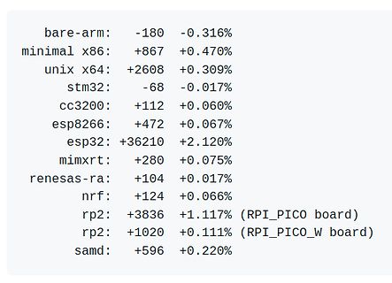
 Bild
Bild
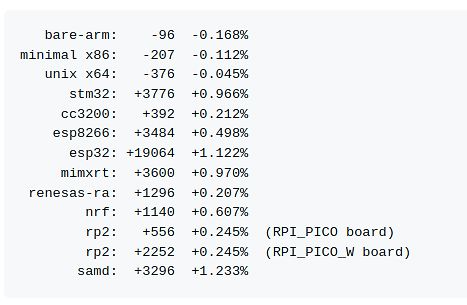
 Bild
Bild