-
PDF
Lankarte.pdf
LUT23 CRC_XOR16 2 A1 B1 18 CRC_MUX16 14 CLKEN CRC16 2 A1 B1 18 DBUS15 CRC7 9 A8 B8 11 CRCLOOP7 29 A8 O8 10 LUT24 CRC5 4 CRC_XOR17 3 A2 B2 17 CRC_MUX17 1 OC1 CRC17 3 A2 B2 17 DBUS14 7486N CRC_POLY_ADDR0 31 A9
in „Space Age 2 der 32Bit MIPS Rechner in TTL“ · Projekte & Code ·
-
 Bild
Bild
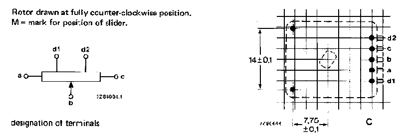
Technische Zeichnung eines Rotors und Schiebers
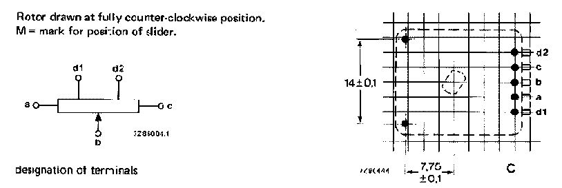
Rotor drawn at fully counter-clockwise position. M= mark for position of slider. d1 d2 a c b 14±0,1 7,75 ±0,1 d1 a b c d2 designation of terminals
in „Suche Tipp für Encoder“ · Mikrocontroller und Digitale Elektronik · · Diagramme
-
Datei
usbdrvasm.S
W32 */ # define argLen r18 /* argument 2 */ # define argPtrL r16 /* argument 1 */ # define argPtrH r17 /* argument 1 */ # define resCrcL r16 /* result */ # define resCrcH r17 /* result */ # define ptrL ZL # define ptrH ZH # define ptr Z # define byte r22 # define bitCnt r19 # define polyL r20 # define polyH r21 # define scratch r23 #else /* __IAR_SYSTEMS_ASM__ */ /* Register assignments for usbCrc16 on gcc */ /* Calling conventions on gcc: * First parameter passed in r24/r25, second in r22/23 and so on. * Callee must preserve r1-r17, r28/r29 * Result is passed in r24/r25 */ # define argLen r22
in „Problem mit libUSB - wie Gerät ansprechen?“ · Softwareentwicklung ·
-
Datei
SHT11.asm
----------------------- ; CRC x^8+x^5+x^4+1 ; 21 Word/131 Cycles (32µs @ 4MHz) ; ; in : r16 Byte ; r17 CRC alt ; out : r17 CRC neu sht11_crc: push r16 push r18 push r19 ldi r19,8 ; 8 Bits sht11_crc10: clr r18 lsl r16 ror r18 ; Bit7
in „SHT71 Assembler Code für Atmega8“ · Mikrocontroller und Digitale Elektronik ·
-
Datei
RFM12.inc
+0 lds ZH,rf_pbuffer+1 st Z+, r16 sts rf_pbuffer+0,ZL sts rf_pbuffer+1,ZH lds r17,(RF_CRC) eor r17,r16 ; CRC berechnen sts (RF_CRC),r17 rjmp int0_end_c ; und raus hier int0_received_EOT: lds r17,(RF_FLAGS) cbr r17,(1<<rx_start) ; Start-Flag zurücksetzen sts (RF_FLAGS),r17 lds ZL,rf_pbuffer+0 lds ZH,rf_pbuffer+1 clr r16 st Z,r16 ; erstmal Stringende (0) speichern // CRC check ld r17,-Z ; high Nibble [ASCIIhex] CRC ld r16,-Z ; low Nibble [ASCIIhex] CRC lds r18,(RF_CRC) eor r18,r16 eor r18,r17 subi r16,'0' ; ASCIhex[B1,B0] zu HEX Wandlung subi r17,'0' cpi r16,10 brsh
in „RFM12 Statusabfrage“ · Mikrocontroller und Digitale Elektronik ·
-
Datei
Spi_Unit.vhd
(12) xor CRC_Data(13) xor CRC_Data(14) xor CRC_Data(15) xor CRC_Data(16) xor CRC_Data(17) xor CRC_Data(18) xor CRC_Data(20) xor CRC_Data(21) xor CRC_Data(22) xor CRC_Data(23) xor CRC_Data(24) xor CRC_Data(28) xor
-
Datei
rfid.c
counter; uint8_t bit; uint8_t byte; uint8_t sequence; uint8_t byte_count; byte_count=length; // compute CRC and add to databuffer // crc is only needed for read and write commands uint16_t CRC_checksum = CRC16 ((uint8_t*)data_buffer, byte_count); data_buffer[byte_count] = (uint8_t)(CRC_checksum & 0x00FF);
in „Zeiterfassungssystem“ · Mikrocontroller und Digitale Elektronik ·
-
Datei
sdcard_tb.vhd
correct argument(2) fourbitmode <= '1'; end if; -- supported commands will return answer, correct crc is not yet done if (SD_received_command = 3 or SD_received_command = 6 or SD_received_command = 7 or SD_received_command = 8 or SD_received_command = 16 or SD_received_command = 17 or SD_received_command
-
Datei
crc32_8.v
[26], next_crc[27], next_crc[28], next_crc[29], next_crc[30], next_crc[31]}; end else if (~calc & d_valid) begin crc_reg <= {crc_reg[23:0], 8'hFF}; crc <= ~{crc_reg[16], crc_reg[17], crc_reg[18], crc_reg[19], crc_reg
in „Ethernetcontroller - Marvell PHY 88e1111“ · FPGA, VHDL & Co. ·
-
Datei
CRC.o.lst
CRC, um bei Unterbrechung der CRC-Unit an alter Stelle weitermachen zu kö 17:../CRC.cpp **** * 18:../CRC.cpp **** * @param CurrentCrc : jetzige CRC 19:../CRC.cpp **** * @param DesiredCrc : gewünschte CRC
in „Problem mit GCC-Optimierung“ · Mikrocontroller und Digitale Elektronik ·
-
Datei
Bluetooth_Geruest.ino
== "XXCHECKXX\r\n") { String temp = ""; stringComplete = false; block = true; for (int i = 0; i < 17; i++) { temp = temp + configs[ i]; if (i != 17) temp = temp + ","; } uint16_t value = 0; byte buf[temp.length() + 1]; temp.getBytes(buf, sizeof(buf)); value = calc_crc(buf, sizeof(buf) - 1, 0xffff);
in „Kleines Android-Arduino-Stepper Projekt“ · Softwareentwicklung ·
-
Datei
tfrec-d-dump.txt
: 180 DEGR Wind-Speed = 0.0 km/h Gust: 04 Value: 00 00 .00 CRC: 07 00 BAD 1 RSSI 86 Offset 22kHz (CRC 10 89) #001 1521900216 2d d4 2d 2d 86 75 6a 60 d0 56 8a ID 2d2d +27.5 0% seq d lowbat 0 RSSI 73 #002 1521900217 2d d4 7e 3a 87 85 17 60 00 56 52 ID 7e3a +38.5
in „SDR-Dekoder für TFA KlimaLogg Pro/IT+ Temperatursensoren“ · Projekte & Code ·
-
Datei
sdcard_tb.vhd
41) then SD_dataBuf <= x"3F80FF8000FF"; end if; -- supported commands will return answer, correct crc is not yet done if (SD_received_command = 3 or SD_received_command = 7 or SD_received_command = 8 or SD_received_command = 17 or SD_received_command = 24 or SD_received_command = 55 or SD_received_command
-
PDF
KWB_RS485_Protokoll.pdf
noch eine weiter „2“ im Protokoll vorhanden ist. Die invertieren die CRC in diesem Fall einfach. int Checksum(unsigned char* data, unsigned char length) { int i; unsigned char crc = 0; crc = data[0]; // = 0x02 for (i = 1; i < length; i++) { crc = rotl(crc, 1); if (crc + data[i] > 255) { crc = crc + data[i] + 1; } else crc = crc + data[i]; } return crc; } Python Script Hier die Protokolldaten für das Python Skript von Markus Heberling (markus_h62) und haros (Gast) aaSignalMaps[16] = { #
-
PDF
5000tl.pdf
byte 1 0x64 0xCF 0x00 0x20 0x02 Slave message Response Slave Function Address Address data to data to CRC CRC number Write High Low write write low Low High word high byte byte 1 0x64 0xCF 0x00 0x20 0x02 CRC 16 CALCULATION CRC16 = 0xFFFF CRC16 = CRC16 xor DATA n = 0 RIGHT SHIFT CRC16 YES CARRY CRC16 = CRC16
in „Firmware mod Kit“ · Mikrocontroller und Digitale Elektronik ·
-
Datei
MJoy.asm
r1, r0 ; Step 4: Divide by 128 lsl r16 rol r17 rol r18 lsl r16 rol r17 rol r18 mov r16, r17 mov r17, r18 ; the result is in r17:r16 register andi r17, 3 subi r16, 0 sbci r17, 2 andi r17, 3 ; the result is in r17:r16 register ret ;****************
in „IGOR USB lässt sich nicht assemblieren“ · Mikrocontroller und Digitale Elektronik ·
-
PDF
AS3955_DS000400_2-00.pdf
address range NAK_0, SLEEP fully not existent Page 56 amsDatasheet Document Feedback [v1-07] 2016-Nov-17 AS3955 − Detailed Description AS3955 nak_on_crc_parity=1 Command Condition AS3955 (empty fields have same nak_on_crc_parity=0 reply as nak_on_crc_parity=0) Memory address range Send existing memory T2T
in „AS3955 External Power“ · Mikrocontroller und Digitale Elektronik ·
-
Datei
main.asm
0000783e w .text 00000000 __init 0000788c w .text 00000000 __vector_13 000078b8 g .text 00000000 usbCrc16Append 0000788c w .text 00000000 __vector_17 0000788c w .text 00000000 __vector_19 0000788c w .text 00000000 __vector_7 00007fcc g F .text 00000010 __eerd_byte_m32 000077ec g O .text 00000012 usbDescriptorConfiguration
in „ATMEGA32 Minimum System Board“ · Mikrocontroller und Digitale Elektronik ·
-
PDF
2005w-TI2-U2.pdf
; add bytes 0..3 9 10 andcc #$fe 11 next 12 lda b, x 13 adca b, y 14 sta b, x 15 decb 16 bpl next 17 18 swi 19 20 e fcb $44, $ff , $33, $11 ; $99007733 21 f fcb $54, $01, $44, $22 andreas.schmied@uni-ulm.de TI-Ubung 2 (WS2005) 6 CRC – Allgemeines ≥ Pru¨summenberechung ≥ Aufspur¨n von Ubertragungsfehlern ≥ Basiert auf Polynomdivison in Z 2 ≥ Beispiel-Datei crc.a Literatur ≥ The CRC Pitstop: http://www.ross.net/crc/ ≥ Ross N. Williams ≥ siehe Paper A painless guide to CRC...“ ” ≥ Englische Wikipedia: CRC32 ≥ CRC-Calculator + Links http://www.zorc.breitbandkatze.de
in „6809 Assembler Frage“ · Mikrocontroller und Digitale Elektronik ·
-
Datei
Modbus_test.bas
----------- '************************************************************ Sub Send_exception Local Crc As Word Mbuf_rcv(2) = Mbuf_rcv(2) + &H80 Crc = Crcmb(mbuf_rcv(1) , 3) ' create checksum Mbuf_rcv(4) = Low(crc) 'add to buffer Mbuf_rcv(5) = High(crc) 'add to buffer Printbin Mbuf_rcv(1) ; 5 End Sub
in „Basecom Modbus Slave Client“ · Mikrocontroller und Digitale Elektronik ·
-
Datei
crc_check.vhd
ENTITY CRC IS PORT ( RESET : IN STD_LOGIC; TX_CLK : IN STD_LOGIC; DATA_IN : IN STD_LOGIC_VECTOR (31 DOWNTO 0); CTRL_IN : IN STD_LOGIC_VECTOR (3 DOWNTO 0); CRC_CHECK : OUT STD_LOGIC ); END CRC; ARCHITECTURE CRC OF CRC IS SIGNAL i_crc : std_logic_vector(15 downto 0); SIGNAL i_crc_2 : std_logic_vector(15 downto 0); SIGNAL data_buf : std_logic_vector(31 downto 0); SIGNAL d : std_logic_vector(47 downto 0); SIGNAL c :
-
PDF
KWB_RS485_Protokoll.pdf
noch eine weiter „2“ im Protokoll vorhanden ist. Die invertieren die CRC in diesem Fall einfach. int Checksum(unsigned char* data, unsigned char length) { int i; unsigned char crc = 0; crc = data[0]; // = 0x02 for (i = 1; i < length; i++) { crc = rotl(crc, 1); if (crc + data[i] > 255) { crc = crc + data[i] + 1; } else crc = crc + data[i]; } return crc; } Python Script Hier die Protokolldaten für das Python Skript von Markus Heberling (markus_h62) und haros (Gast) aaSignalMaps[16] = { #
-
Datei
bootload.lst
--------------- 132 #define appl r16 // rjmp to application 133 #define APPL r16 134 #define apph r17 135 #define APPH r17 136 #define polynoml r18 // CRC polynom 0xA001 137 #define POLYNOML r18 138 #define polynomh r19 139 #define POLYNOMH r19 140 141 #define zx r21 // 3 byte Z pointer 142 #define ZX
in „Peter Danneggers Bootloader (fastboot) für AVR-GCC-Toolchain“ · Projekte & Code ·
-
Datei
lpc17xx_emac.c
*/ /* Includes ------------------------------------------------------------------- */ #include "lpc17xx_emac.h" #include "lpc17xx_clkpwr.h" /* If this source file built with example, the LPC17xx FW library configuration * file in each example directory ("lpc17xx_libcfg.h") must be included, * otherwise
in „LPC1768 Ethernet mit DP83848J“ · Mikrocontroller und Digitale Elektronik ·
-
Datei
libsht.c
[statusreg & 15]); if (mode ==TEMP) crc =pgm_read_byte(&CRC_TABLE[crc ^ MEASURE_TEMP]); else if(mode == HUMI) crc = pgm_read_byte(&CRC_TABLE[ crc ^ MEASURE_HUMI]); else crc =255; // error: mode is not recognized crc = pgm_read_byte(&CRC_TABLE[crc ^ ((*p_sht_value).i >> 8)]); crc = pgm_read_byte(&CRC_TABLE[crc ^ ((*p_sht_value).i & 0x00ff)]); return (crc==pgm_read_byte(&REVERSED_BIT_ORDER_LIST[*p_checksum])); } /* The following functions should
in „SHT11 misst Mist“ · Mikrocontroller und Digitale Elektronik ·
-
Datei
SHT_TEST.c
[statusreg & 15]); if (mode ==TEMP) crc =pgm_read_byte(&CRC_TABLE[crc ^ MEASURE_TEMP]); else if(mode == HUMI) crc = pgm_read_byte(&CRC_TABLE[ crc ^ MEASURE_HUMI]); else crc =255; // error: mode is not recognized crc = pgm_read_byte(&CRC_TABLE[crc ^ ((*p_sht_value).i >> 8)]); crc = pgm_read_byte(&CRC_TABLE[crc ^ ((*p_sht_value).i & 0x00ff)]); return (crc==pgm_read_byte(&REVERSED_BIT_ORDER_LIST[*p_checksum])); } /* The following functions should
in „SHT11 an ATmega2560 Es funktioniert nicht“ · Mikrocontroller und Digitale Elektronik ·
-
PDF
nRF2401rev1_1.pdf
to 5 byte address for RX channel 1 ™ r 23:18 6 ADDR_W Number of address bits (both RX channels). u 17 1 CRC_L 8 or 16 bit CRC k o h S 16 1 CRC_EN Enable on-chip CRC generation/checking. 15 1 RX2_EN Enable two channel receive mode i 14 1 CM Communication mode (Direct or ShockBurst™) a u i 13 1 RFDR_SB
in „Externe Antenne für Funkmodul TRW24G“ · HF, Funk und Felder ·
-
Datei
bootload.lst
--------------- 132 #define appl r16 // rjmp to application 133 #define APPL r16 134 #define apph r17 135 #define APPH r17 136 #define polynoml r18 // CRC polynom 0xA001 137 #define POLYNOML r18 138 #define polynomh r19 139 #define POLYNOMH r19 140 141 #define zx r21 // 3 byte Z pointer 142 #define ZX
in „Peter Danneggers Bootloader (fastboot) für AVR-GCC-Toolchain“ · Projekte & Code ·
-
PDF
sl11hspec.pdf
Specification Rev 1.15 January 24, 2000 3.3V power source Rev 1.16 February 8, 2000 Update from Rev 1.15 Rev 1.17 February 17, 2000 Update from Rev 1.16 ©1996 - 2000 ScanLogic Corporation. All rights reserved. SL11H/T USB Host/Slave Date: 02/17/00 Controller is trademark of ScanLogic Corporation. The information
in „[V] SL11H, USS720E ua.“ · Markt ·
-
PDF
ProdManualIndGradeSDv1.0.pdf
.........................................................4-17 4.7.1. CRC and Illegal Command.....................................................................................................4-17 4.7.2. Read, Write and Erase Time-out Conditions ..............
in „Eigenbau Mp3 Player“ · Mikrocontroller und Digitale Elektronik ·
-
Datei
crc32.c
uint8 b) { STEPCRC(crc,b); return(crc); } uint32 CRC32_AddWord(uint32 crc,uint16 w) { uint8 *ptr; ptr = (uint8 *)&w; STEPCRC(crc,ptr[0]); STEPCRC(crc,ptr[1]); return(crc); } uint32 CRC32_AddLong(uint32 crc,uint32 l) { uint8
in „Ideen um CRC-Routine zu beschleunigen? (AVR, gcc)“ · Mikrocontroller und Digitale Elektronik ·
-
Datei
main.cpp
0xFF); data[14] = ((epochTime >> 8) & 0xFF); data[15] = ((epochTime & 0xFF)); data[16] = 0x00; data[17] = 0x00; data[18] = 0x00; data[19] = 0x05; crc16.restart(); crc16.add(&data[10], 14); data[24] = (crc16.getCRC() >> 8) & 0xFF; data[25] = crc16.getCRC() & 0xFF; crc8.restart(); crc8.add (&data[0], 26
in „Wechselrichter Hoymiles HM-xxxx 2,4 GhZ Nordic Protokoll?“ · Mikrocontroller und Digitale Elektronik ·
-
PDF
RF-24G_datasheet.pdf
and can be set to logic 0. ADDR_W& CRC ADDR_W CRC_L CRC_EN 23 22 21 20 19 18 17 16 Table 8 Number of bits reserved for RX address + CRC setting. Bit 23 – 18: ADDR_W: Number of bits reserved for RX address in ShockBurst packages. NOTE: Maximum number of address bits is 40 (5 bytes). Values over 40 in ADDR_W are not valid. Bit 17: CRC_L: CRC length to be calculated by TRF-2.4G in ShockBurst. Logic 0: 8 bit CRC Logic 1: 16 bit CRC Bit: 16: CRC_EN: Enables on-chip CRC generation (TX) and verification (RX). Logic 0: On-chip CRC
in „[V] Grafik-LCDs, Pictiva-LCDs, TRW-24G Funkmodule“ · Markt ·
-
PDF
Sensirion_Humidity_SHT1x_SHT7x_CRC_Calculation_V1.pdf
213 66 115 32 17 63 14 93 108 251 202 153 168 48 49 50 51 52 53 54 55 56 57 58 59 60 61 62 63 0011’1101 3D 61 Reversed Final CRC 197 244 167 150 1 48 99 82 124 77 30 47 184 137 218 235 value 64 65 66 67 68 69 70 71 72
in „Brauche Hilfe bei SHT11 CRC Berechnung“ · Mikrocontroller und Digitale Elektronik ·
-
Datei
CRC.cpp
0x04C11DB7 polynomial 0x00000000,0x04C11DB7,0x09823B6E,0x0D4326D9,0x130476DC,0x17C56B6B,0x1A864DB2,0x1E475005, 0x2608EDB8,0x22C9F00F,0x2F8AD6D6,0x2B4BCB61,0x350C9B64,0x31CD86D3,0x3C8EA00A,0x384FBDBD }; Crc = Crc ^ Data; // Apply all 32-bits // Process 32-bits, 4 at a time, or 8 rounds
in „Problem mit GCC-Optimierung“ · Mikrocontroller und Digitale Elektronik ·
-
Datei
main.lss.txt
endpoint */ e14: 1e e1 ldi r17, 0x1E ; 30 usbMsgLen = USB_NO_MSG; } usbTxLen = len; e16: 10 93 60 00 sts 0x0060, r17 usbCrc16Append(&usbTxBuf[1], len); len += 4; /* length including sync byte */ if(len < 12) /* a partial package identifies
in „2 Programme in einem AVR“ · Mikrocontroller und Digitale Elektronik ·
-
PDF
Atmel-9626-AT42-QTouch-BSW-AT421085-Object-Protocol-Guide_Datasheet.pdf
byte2 — byte3 — byte4 — byte5 — byte6 — byte7 The checksum could be calculated as follows: uint32_t CRC = 0; CRC = crc24(CRC, byte1, byte2) CRC = crc24(CRC, byte3, byte4) CRC = crc24(CRC, byte5, byte6) CRC = crc24(CRC, byte7, 0) /* <- zero added for the last checksum */ CRC = CRC & 0x00FFFFFF; /* <- mask
in „Atmel AT42QT1085“ · Mikrocontroller und Digitale Elektronik ·
-
Datei
crc.txt
AX25 @KS de:DC4OX 13.08.89 13:19 5 3642 Bytes ERKLAERUNG CRC 1/10 *** Bulletin-ID: 315803DK0MAV *** de DB8AS @ DB8AS CRC Teil 1 von 10 CRC Cyclic Redundancy Check / FCS Frame Check Sequence "Vorwort" Ich will mich bemuehen, da anscheinend doch das Interesse besteht
in „Pocsag Checksumme berechnen“ · Mikrocontroller und Digitale Elektronik ·
-
PDF
sd_mmc.pdf
Blockgro e a dern (CMD16) . . . . . . . . . . . . . . . . . . . . . 15 4.2.2 Einzelnen Block lesen (CMD17) . . . . . . . . . . . . . . . . . . . . 15 4.2.3 Einzelnen Block schreiben (CMD24) . . . . . . . . . . . . . . . . . 16 5 Dateisystem? 17 6 Quellenangaben 17 2 1 Einfuh ung 1.1 Was ist eine SD-Karte
in „MMC-Karte funktioniert nicht“ · Mikrocontroller und Digitale Elektronik ·
-
Datei
crc32_opencores.vhd
ieee.std_logic_1164.all; entity crc is port ( data_in : in std_logic_vector (63 downto 0); crc_en , rst, clk : in std_logic; crc_out : out std_logic_vector (31 downto 0)); end crc; architecture imp_crc of crc is signal lfsr_q: std_logic_vector
-
Datei
Alaska.v
-CRC-OUTPUT MSB/LSB-Auswahl Button3 reg [7:0]CRC1; reg [7:0]CRC2; reg [7:0]CRC3; reg [7:0]CRC4; always @(posedge WCLK) begin if (!B3) begin CRC1 <= {CRCm[31:24]}; end else if (B3) begin CRC1 <= {CRCm[0],
in „Ethernetcontroller - Marvell PHY 88e1111“ · FPGA, VHDL & Co. ·
-
PDF
EPOS_Communication_Guide_En.pdf
++; //Copy next DataWord to c do { carry = CRC & 0x8000; //Check if Bit15 of CRC is set CRC <<= 1; //CRC = CRC * 2 if(c & shifter) CRC++; //CRC = CRC + 1, if BitX is set in c if(carry) CRC ^= 0x1021; //CRC = CRC XOR G(x), if carry is true shifter
in „STM32 - Umstieg von UART auf CAN“ · Mikrocontroller und Digitale Elektronik ·
-
Datei
TX22IT.cpp
:7 NewBatt:0 Error:1 Temp:--- Hum:--- Rain:27.00 Wind:25.40m/s from:292.50 Gust:--- CRC:3A TX22IT [A 1 D 2 2 0 1 B 3 E F E 17 ] CRC:OK S:A ID:7 NewBatt:0 Error:1 Temp:--- Hum:--- Rain:27.00 Wind:25.40m/s from:315.00 Gust:--- CRC:17 TX22IT [A 1 C 3 1 0 7 3 2 0 1 B 4 0 0 0 8A ] CRC:OK S:
in „SDR-Dekoder für TFA KlimaLogg Pro/IT+ Temperatursensoren“ · Projekte & Code ·
-
PDF
SL13A_Datasheet.pdf
COMMAND CODE UID CRC EOF 8 bits 0x2A 64 bits 16 bits Reply: SOF FLAGS CRC EOF 8 bits 16 bits Reset to Ready - #11 Request: SOF FLAGS COMMAND CODE UID CRC EOF 8 bits 0x26 64 bits 16 bits Reply: SOF FLAGS CRC EOF 8 bits 16
in „SL13A temperatur auslesen Arduino UNO“ · Mikrocontroller und Digitale Elektronik ·
-
Datei
mmc.c
* @def MSK_RESPFS * Bitmask: Set by hardware when the format of a response is correct. * @def MSK_CRC7S * Bitmask: Set by hardware when the CRC7 computed in the response is correct. * This bit is not relevant when CRCDIS is set. * @def MSK_DATDIR * Bitmask: Set to select data transfer from host to card
in „MMC Bus am AT89C5132/SND1“ · Mikrocontroller und Digitale Elektronik ·
-
PDF
AN_MMCA050419.pdf
] 1 0 10000000 [CRC16] 1 DATA4 0 10xxxxxxxxxxxx [CRC16] 1 0 01000000 [CRC16] 1 DATA5 0 01xxxxxxxxxxxx [CRC16] 1 0 10000000 [CRC16] 1 DATA6 0 10xxxxxxxxxxxx [CRC16] 1 0 01000000 [CRC16] 1 DATA7 0 01xxxxxxxxxxxx [CRC16]
in „MMC SD library FAT16 FAT32 read write“ · Projekte & Code ·
-
Datei
ESP_Download_Tool_v2.4_Log.txt
check_err_4: 0b ==================== EFUSE NORMAL MODE ==================== ========================= CRC IN MODE 1: crc_calc_res: 73 target crc val: 73 ========================= ========================= CRC IN MODE 1: crc_calc_res: 73 target crc val: 73 ========================= ================== EFUSE
-
PDF
m3s_v2-0.pdf
curCrc = vInitialValue ; // i n i t i a l value 42 unsigned short cnt ; // counter for <=256 Bytes 13 43 44 for ( cnt=0; cnt < vFrameLength ; cnt++) 45 f 46 curCrc = crc8 array [ curCrc ^ rFrame [ cnt ] ]
in „API-Feedback / Protokollfeedback: Kommunikationsstack für serielle Bussysteme“ · Mikrocontroller und Digitale Elektronik ·
-
PDF
tps92661-q1.pdf
crc_calc; // Calculated CRC Uint8 crc_msb, crc_lsb; // Individual bytes of calculated CRC // Calculate the CRC based on bytes received crc_calc = crc_16_ibm(rx_buf, crc_start); crc_lsb = (crc_calc & 0x00FF); crc_msb = ((crc_calc >> 8) & 0x00FF); // Perform the bit reversal within each byte crc_msb = reverse_byte(crc_msb); crc_lsb = reverse_byte(crc_lsb); // Do they match? if((*(rx_buf + crc_start) == crc_lsb
in „LED Serienschaltung mittels Transistor schalten“ · Analoge Elektronik und Schaltungstechnik ·
-
PDF
IgorPlug-USB__AVR__firmware.pdf
DoReceiveSetupData =2 10.equ DoPrepareOutContinuousBuffer =3 10.equ DoReadySendAnswer =4 107 108 10.equ CRC5poly =0b00101 ;CRC5 polynom 11.equ CRC5zvysok =0b01100 ;CRC5 zvysok po uspesnpm CRC5 11.equ CRC16poly =0b1000000000000101 ;CRC16 polynom 11.equ CRC16zvysok =0b1000000000001101 ;CRC16 zvysok po uspesnom
in „IGORPLUG-USB“ · Mikrocontroller und Digitale Elektronik ·