. . . . C C C C 6 6 W W W 1 2 3 4 5 BasicConnector R663 9 2 AC INLET (A SIDE) AC INLET (B SIDE) CN90 9 X L FH92 C L RX92 RX91 CUP12674Z-3 MP VT91 V 3 0 Y 9 0 2 R RX94 R F H A A 0 I 9 4 L R T LF91 JK90 P FH91 Pb M M 1 2 3 4 5 6 7 8 9 10 11 12 13 14 15 16 52 1 2 3 4 5 6 7 8 9 10 11 12 13 14 15 16 A A
CONN. (90) 76382-404 1 J3439163 15P MALE CONNECTOR P.2 M 1 13369564 B12B-PH-K-S CONNECTOR 1 J3439172 8P MALE CONNECTOR 90 P.2 M 3 J3439182 5P MALE CONNECTOR 90 P.2 M 3 J3439175 11P MALE CONNECTOR 90 P.2 M 2 J3439183
CONN. (90) 76382-404 1 J3439163 15P MALE CONNECTOR P.2 M 1 13369564 B12B-PH-K-S CONNECTOR 1 J3439172 8P MALE CONNECTOR 90 P.2 M 3 J3439182 5P MALE CONNECTOR 90 P.2 M 3 J3439175 11P MALE CONNECTOR 90 P.2 M 2 J3439183
more V R CENTER ....................................................................................90 W X SURROUND L/R ...........................................................90 W + 90 Wal Noise (IHF-A Network) R SURROUND BACK L/R ................................................90 W + 90 W FRONT L
Host Reset Global without Trigger Power with Power Reset with Cycle Cycle Power Cycle Write of 0Eh to CF9h Register when Global Reset No Yes No (Note 1) bit = 0b Write of 06h to CF9h Register when Global Reset Yes No No (Note 1) bit = 0b Write of 06h or 0Eh to CF9h register when Global No No Yes Reset bit
kann, aber wie kommt man von TTL wieder auf USB oder ähnliches? https://www.ti.com/product/de-de/DS90CF364 Pinbelegung vom BMW LVDS-Stecker 1 -> LVDS Channel 2+ 2 -> LVDS Channel 2- 3 -> -- 4 -> LVDS Channel 1+ 5 -> LVDS Channel 1- 6 -> LVDS clock + 7 -> LCDS clock - 8 -
restlichen 6 dann die jeweilige Farbe. Aber der minimale Takt ist ein Problem, der vom TO vorgeschlagene DS90CF364 geht bissl weiter runter, vielleicht koennte der das grad' ab - muesste man halt mal den Takt messen - aber selbst wenn: das hilft ja nicht so wirklich weiter. Denn dann haste 'nen breiten
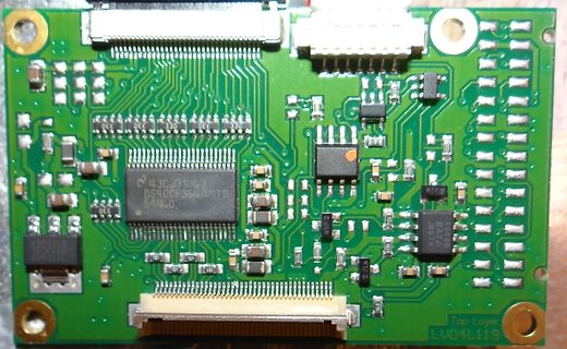
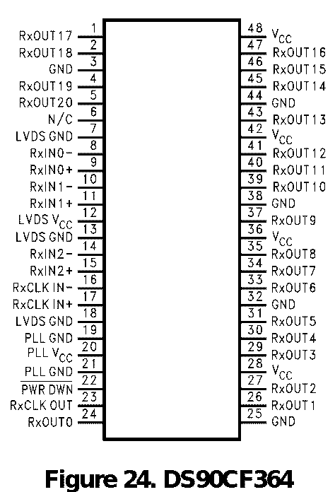
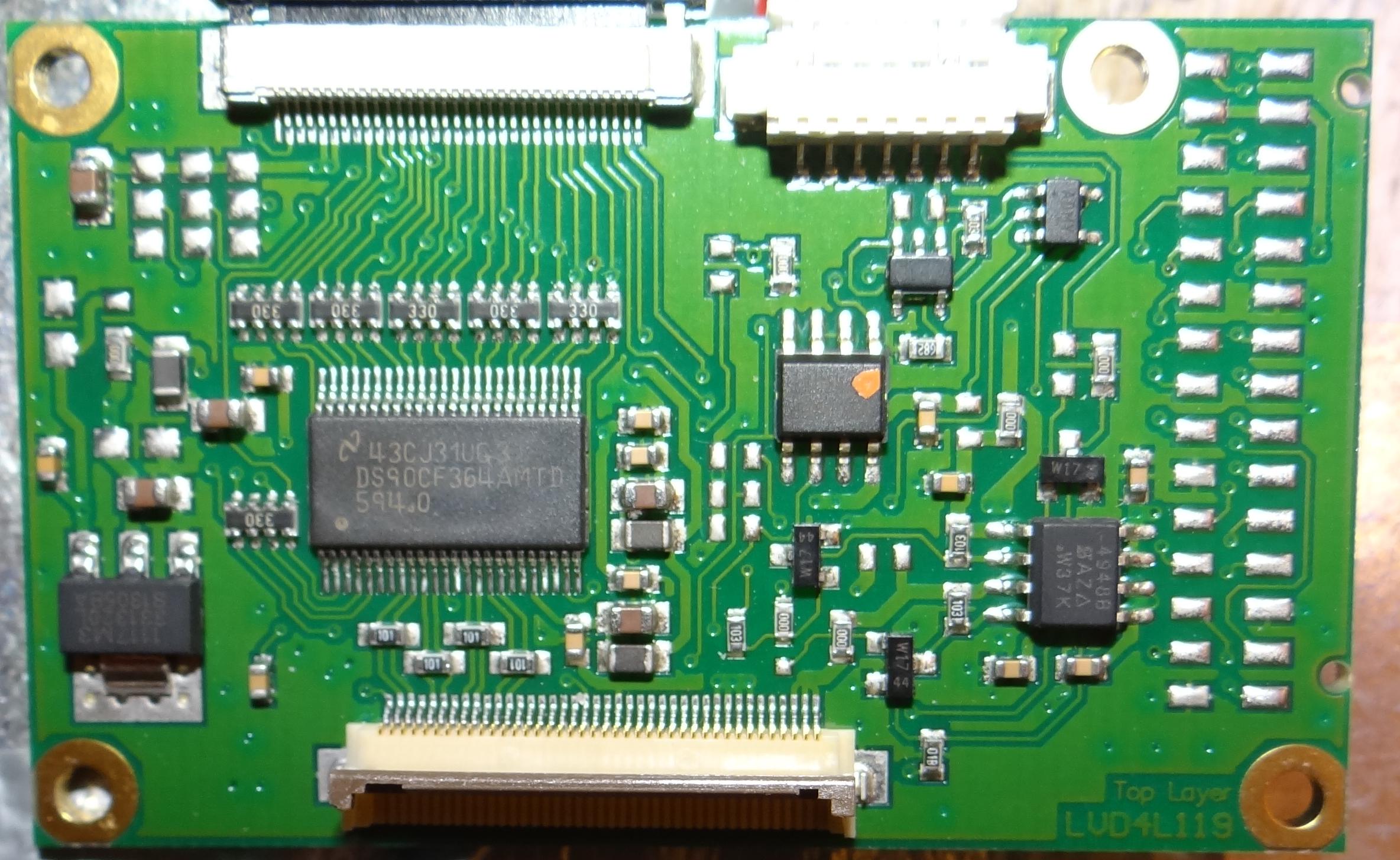
muss ein 32-poliges Flexkabel sein. > Dieses geht in ein Interfaceboard, was auf 40-Pin (mit einem DS90CF364) > konvertiert. Über eine 2 x 20 Pin Steckverbindung wird dann das > Messgerät angeschlossen, was mit einem 40-Pin Flachbandkabel verbunden > wird. Hier ist schon mal das DB des DS90Cf364 https://www.ti.com/lit/ds/symlink/ds90cf364.pdf
Y Y NC 14 F F F 0.01 SW C C R CF88 12 12 15 GND CF99 4 3 2 110/50V D D load(0) V C 6 V C 6 GND D B RF73 0 D B RF73 0 5 E - 9 8 7 6 5 4 3 2 1 8 8 - F D T T 9 CF60 Dummy CF60 Dummy S J V U - J D D D S S S CF59 Dummy +24V CF59 Dummy +24V
quadrature combiner circuits operating at Input RF High Gain tA audioftmp. RF. We sometimes show a 90-degree LO/ phase shift in one path with none in an- 7-7.1 other where actual circuitry merely main- MHz tains a 90-degree difference. Audio ic/iPJ RF Power These figures offer a glimpse of what Amplifier
a” coeffiient The infinitesimal length of the fluid trajectory can be assessed through (3.69). 2 2 ds = √ dθ + dr (3.69) Wheredθ = w dtθs tangentialcomponentanddr = w dtis therradialcomponent, as shown in Fig. 3.9. When ∑NR ds islowerthantheentranceregionlength,thecoefficientfornotfully i=0 NR developed
12.5 MHz and less 25 — ns pulse to X0 only Input clock rising/falling timeCR, X0, X1 — — 8 ns (CR + CF) tCF fCP — CPU system 0.625*2 25 MHz Internal operating clock frequency fCPP — Peripheral system 0.625*2 25 MHz Internal operating clock tCP — CPU system 40 1600*2 ns cycle time 2 tCPP — Peripheral system
temperature range: -40°C to +105°C ranging from 2.3V to 6.0V in increments of 0.1V. ●Package SSOP5: 2.90mm x 2.80mm x 1.25mm ●Features ▯ High accuracy detection SSOP3: 2.92mm x 2.80mm x 1.25mm ▯ Ultra-low current consumption ▯ Two output types (Nch open drain and CMOS output) VSOF5: 1.60 mm x 1.60mm x 0.60mm
Read as ‘0’ Note: Bit PEIE of the INTCON register must be set to enable any peripheral interrupt. DS40001574D-page 90 2011-2017 Microchip Technology Inc. PIC16(L)F1938/9 REGISTER 7-5: PIR1: PERIPHERAL INTERRUPT REQUEST REGISTER 1 R/W-0/0 R/W-0/0 R-0/0 R-0/0 R/W-0/0 R/W-0/0 R/W-0/0 R/W-0/0 TMR1GIF
und das Wissen das dahinter steckt ... Schon sehr beeindruckend. Leider leider entwickeln sich 90% eines Programms in 10% der Zeit ... Die anderen 10% benötigen dann 90% Zeit. Die zeitaufwändigen Sachen kommen vermutlich erst ... Bug-fixing und Usability ... Das ist dann immer das Stadium, in
aufgrund ihrer Industrietauglichkeit bei uns gesetzt... MIPI DSI auf LVDS habe ich gefunden (TI SN65DS185) aber primitives parallel RGB ist mir nicht untergekommen... Ich wäre für eine Lösung dankbar. (Und ja, FPGA mit passender IP geht auch... ich hätte aber gerne einen Chip...)
nicht sonderlich teuer. Als "Bridge" würde ich das auch nicht bezeichnen. http://www.ti.com/product/DS90CF364 http://www.ti.com/product/DS90CF364 für 18- und 24-Bit-Displays.
- ",F >40 F1=1/F >50 C=(F1/T)/2 : REM CALCULATE RELOAD VALUE >60 IF C<20 THEN 30 >80 IF C1<.5 THEN 90 : C=C+1ATE FRACTION >90 PRINT : PRINT "THE DESIRED FREQUENCY IS - ",X,"HZ" >100 C=INT(C) : PRINT >110 PRINT "THE ACTUAL FREQUENCY IS - ",1/(2*C*T),"HZ" >120 PRINT >130 PRINT "THE RELOAD VALUE FOR PWM
- ",F >40 F1=1/F >50 C=(F1/T)/2 : REM CALCULATE RELOAD VALUE >60 IF C<20 THEN 30 >80 IF C1<.5 THEN 90 : C=C+1ATE FRACTION >90 PRINT : PRINT "THE DESIRED FREQUENCY IS - ",X,"HZ" >100 C=INT(C) : PRINT >110 PRINT "THE ACTUAL FREQUENCY IS - ",1/(2*C*T),"HZ" >120 PRINT >130 PRINT "THE RELOAD VALUE FOR PWM
; ΔLED-PP 50mA The chosen components from step 1 are: Δv = 1V IN-PP VTURN-ON= 10V; HYS= 1.1V η = 0.90 1. NOMINAL SWITCHING FREQUENCY Assume COFF= 470pF and η = 0.90. Solve OFF R 2. INDUCTOR RIPPLE CURRENT Solve for L1: The closest standard inductor value is 22 µH therefore the actual L-PPis: The chosen
SCALE MIN 18 RAST VSIZE 1023 G GAIN 127 127 DE GAIN COR 03 RAST HSIZE 895 B GAIN 127 127 DE GAIN CLIP (90/90/60) SHARP OFFSET 17 R,CR OFFSET 54 63 CE UPPER 240 CLK DLY 00 G,Y OFFSET 54 63 CE CUTOFF 64 H_POSI 20 B,CB OFFSET 54 63 CE GAIN 48 VIDEO PATH PC TTX WTE Y THRE 230 AUTO COLOR OFF R CTL 02 SYNC MODE
Refer to the MPASM User's Guide for additional information on * ; features of the assembler (Document DS33014). * ; * ; Refer to the respective PIC data sheet for additional * ; information on the instruction set. * ; * ;********************************************************************** ; * ; Filename
Refer to the MPASM User's Guide for additional information on * ; features of the assembler (Document DS33014). * ; * ; Refer to the respective PIC data sheet for additional * ; information on the instruction set. * ; * ;********************************************************************** ; * ; Filename

 Bild
Bild
 Bild
Bild