messen war. Da sichder Schlei fer in Mittelstellungbefand, mußte der daß der Widerstand R432 hochohmig 163 V eingestelltund das Gerät konnte war. wieder in Betriebgehen. sam Fußpunktwiderstand unterbrochen sein. Nach dem Erneuern des defekten Wider Die Messung mit dem Ohmmeter ergab, standes wurde die
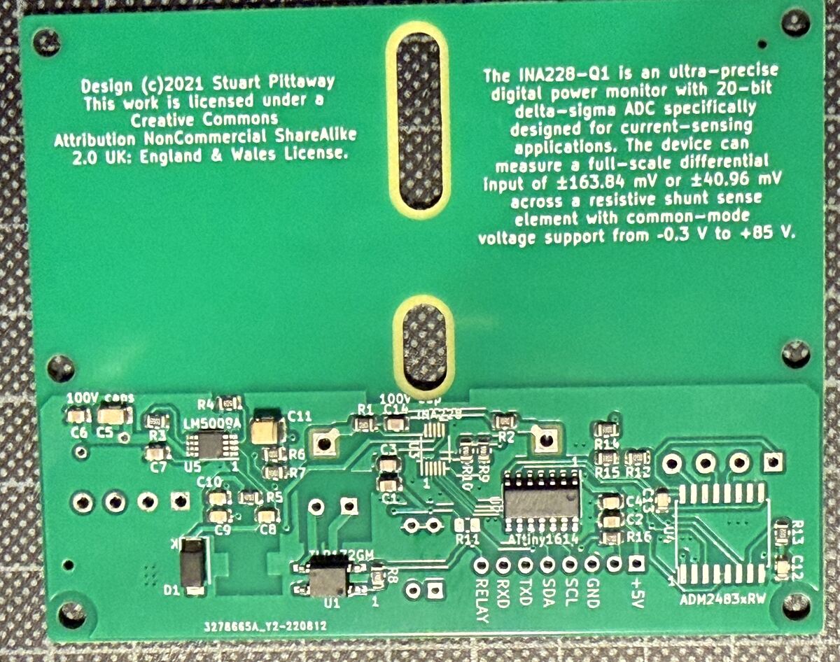
under a Creative Commons Attribution NonCommercial ShareAlike 2.0 UK: England & Wales License. The INA228-Q1 is an ultra-precise digital power monitor with 20-bit delta-sigma ADC specifically designed for current-sensing applications. The device can measure a full-scale differential Input of ±163.84
PE1/ED09/EAD09/T32A06OUTA/EA22/T32A06OUTC/UT0CTS_N T32A09OUTB/TRGIN1/PL7 163 58 PE0/ED08/EAD08/T32A06INB1/T32A06OUTB/EA23/T32A06INA1/UT0RTS_N Motor Control ADC PORT T32A09OUTC/T32A09OUTA/INT03b/PL6 164 57 DVSSC Remote Control I2C4SDA/UT5RTS_N/UT5CTS_N/PJ3 165 56 DVDD3C (91 to
pullup (E3D) * 20 : Pt100 with circuit in the Ultimainboard V2.x with mainboard ADC reference voltage = INA826 amplifier-board supply voltage. * NOTE: (1) Must use an ADC input with no pullup. (2) Some INA826 amplifiers are unreliable at 3.3V so consider using sensor 147, 110, or 21. * 21 : Pt100 with circuit in the Ultimainboard V2.x with 3.3v ADC reference voltage (STM32, LPC176x....) and 5V INA826 amplifier board supply. * NOTE: ADC pins are not 5V tolerant. Not recommended because it's possible to damage the CPU by going over 500°C. * 201 : Pt100 with circuit in Overlord, similar to Ultimainboard
Muss es unbedingt eine selbst gestrickte Schaltung sein oder ginge auch ein INA240?
Hammer einschlagen. Aber es gibt für Dein Problem eben auch geeignetere Werkzeuge. Beispielsweise INA238 (16 Bit Auflösung) https://www.ti.com/lit/ds/symlink/ina238.pdf oder INA228 (20 Bit Auflösung). https://www.ti.com/lit/ds/symlink/ina228.pdf Die messen direkt Spannung und Strom und errechnen
S-Parameter-File im „S2p-Format“, heruntergeladen aus dem Internet für den Mikrowellen-Verstärker-IC vom Typ „INA-03184“ der Firma Agilent: ! INA-03184 S PARAMETERS ! Id = 10 mA LAST UPDATED 07-22-92 # ghz S ma r 50 0.0 .32 180 19.2 0 .014 0 .55 0 0.05 .32 179 19.14 -3 .014 3 .55 0 0.10 .32 176 19.05 -7 .014 4
75mV bei 100A bedeutet 0.75uV bei 1mA. Der INA226 hat ein LSB von 2.5uV. Das sind schon mal 4mA Delta wenn das LSB sich nur um 1 ändert. Bisher war nur von 30A die Rede, für die 100A würde ich auf den INA228 wechseln, der ist gerade bei sehr kleinen
: Kauf dir einen guten 30A Shunt, gib dich erstmal mit +-10mA zufrieden und nimm zum starten einen INA237 (die 16bit Version des INA228 und deutlich preiswerter, Ansteuerung identisch, bis auf das optionale TEMPCOM Register beim INA228) und wenn alles läuft kannst du immer noch den INA237 gegen den IN228
possibleinclination. • The heated air mustdissipate unhindered (fig. d,page 7). • Wheninstallingthe coolingunit ina closed room suchas a wardrobe, pantry or aftcompartment,openingsmusthavea crosssectionof at least 200 cm² (25cm x 8cm) for cooling and exhaust air. • Makesurethattheairflowonthecondenser(fig.d C,page
Periodic Rectangular Pulse T = P ×Z = 100×0.04 = 4°C j −mb thj −mb Whenconsidering thejunctiontemperature ina device,the The value for Z th j-mb taken from the δ=0 curve shown in following formula is used: Fig. 12.Theabovecalculationshowsthatthepeak junction temperature will be 4˚C above the mounting base Tj
com improvements are expected over existing munications, and automatic perimetry sy systems. stems, 163 VHF-COMMUNI CATLQ.~ Another very important characteristic is the subsequent tothe correlator carries out avery possibility01 carrying our exact distance narrow-band processing cnne signal. measu rement
com improvements are expected over existing munications, and automatic perimetry sy systems. stems, 163 VHF-COMMUNI CATLQ.~ Another very important characteristic is the subsequent tothe correlator carries out avery possibility01 carrying our exact distance narrow-band processing cnne signal. measu rement
70 em SSB Transmitter with seem 10be solved . at least 10someextent. High Spurious Rejection Part 1 163-170 According 10 DL 1 au me sensitivity on 1269 MHz is near tne projected value now. alter switching Ihe antenna retais many Hans Joachim Senckel, DF5QZ limes by retecornrnand. A 13 em Fully Tranalstorlzed
Diameter Resistance Surface Load Surface Load Surface Load Surface Load Surface Load in mm in Ω/m I inA in W/cm² I inA in W/cm² I in in W/cm² I inA in W/cm² I inA in W/cm² 0,020 1560 0,0270 1,82 0,0342 2,92 0,0410 4,20 0,0479 5,69 0,0724 13,0 0,022 1290 0,0305 1,75 0,0381 2,74 0,0450 3,82 0,0534 5,31
3,6,7] PWROFF_C2M_B [7,8,11]I2C_SDA_LS SDA NC 5 6 Z1 4 A0 GND_6 11 Q21 A1 GND_11 DMN26D0UFB4-7 AGND1 INA260 INA260 ADDR: 0x40 UTIL_3V3 ALWAYS ON REGULATOR POWER TEST POINTS GROUND LOOPS TP1 TP5 5V0_IN UTIL_3V3 J15 J16 J17 Do Not Stuff Do Not Stuff Do Not StuffDo Not StuffDo Not Stuff 8 1 IN OUT 5V0_IN
TB J ADR_CNTR Trig. -Latch B W42C08A-04 B L . J L . L , r TDC501 — i Status Trig. -Cor. CO O I TRIG_INA r1 It r ' -i Jt State < ; | \I TRIG_IN_B Trig.-Sel. ! +5V L J Maschine -6VV cn TTRACE r- -V_CT(-13V) m i TCH1/TCH2 Trigger _ SET Pulse AT17C65 r B i p ' 'T Start Power l Stop Rec.Clk RESET Conf ig._
ich leider total passen, noch nie gemacht. Habe gerade meinen Displays durchgesehen und das DOG M163B-A gefunden. Nach DB kann man ja damit SPI bei 5V machen und hat den ST7036. Nach dem ersten Blick könnte es funktionieren. Gibt es bestimmte Pins des Attiny 841 die man für SPI nehmen sollte, ausser
bis 6 Slave am Master dran. Beispiel dazu: PCF8574, PCF8591, MCP23008, MCP23017, OLED, E-Paper, INA221, Farb TFT Display von EA mit bis zu 3,2 Zoll. Teilweise habe ich 2 Displays gleichzeitig am Bus betrieben. Auch der Austausch von Atmega zum Attiny 841 und zurück per Bus klappt ohne Probleme
Specification Version 3.01 c Power on n ModeOperation CS ("0")ted Id(idle)te CMD0 from all states except (ina) card doesn'tIt is mandatory for the host compliant CMD8 to send CMo8 before ACMD41.00 host omitted voltage range ACMD41 State(ina) t (Non valid command) Re(ready)te c Start MultiMediaCard CMD11 card
ReadBuf, int MaxRead); ThefunctionTMReadPacketreadsaDefaultDataStructurepacketstartingon”StartPage”inaMemory iButton. The data is placed into ”ReadBuf” up to a maximum of ”MaxRead” bytes. Returns a read count length greater then or equal to 0 for success or one of the following negative values for a
MKS_Base_DKU001327 * 20 : Pt100 with circuit in the Ultimainboard V2.x with mainboard ADC reference voltage = INA826 amplifier-board supply voltage. * NOTES: (1) Must use an ADC input with no pullup. (2) Some INA826 amplifiers are unreliable at 3.3V so consider using sensor 147, 110, or 21. * 21 : Pt100 with circuit in the Ultimainboard V2.x with 3.3v ADC reference voltage (STM32, LPC176x....) and 5V INA826 amplifier board supply. * NOTE: ADC pins are not 5V tolerant. Not recommended because it's possible to damage the CPU by going over 500°C. * 22 : 100k (hotend) with 4.7k pullup to 3.3V and 220R to
S-Parameter-File im „S2p-Format“, heruntergeladen aus dem Internet für den Mikrowellen-Verstärker-IC vom Typ „INA-03184“ der Firma Agilent: ! INA-03184 S PARAMETERS ! Id = 10 mA LAST UPDATED 07-22-92 # ghz S ma r 50 0.0 .32 180 19.2 0 .014 0 .55 0 0.05 .32 179 19.14 -3 .014 3 .55 0 0.10 .32 176 19.05 -7 .014 4
cable. AC coupling blocks the different dc voltage levels from each other on each end of the cable. An INA163 instrumentation amplifier provides differential inputs and receives the balanced audio signals from the cable. The INA163 gain may be set from 0 dB to 80 dB by selecting the R value. The INA163 circuiG
Periodic Rectangular Pulse T = P ×Z = 100×0.04 = 4°C j −mb thj −mb Whenconsidering thejunctiontemperature ina device,the The value for Z th j-mb taken from the δ=0 curve shown in following formula is used: Fig. 12.Theabovecalculationshowsthatthepeak junction temperature will be 4˚C above the mounting base Tj
Current Shunt Monitor, 36V, SOT-23-5 INA168 High-Side Measurement Current Shunt Monitor, 60V, SOT-23-5 INA193 Current Shunt Monitor −16 V to +80 V Common-Mode Range, 20V/V, SOT-23-5 INA194 Current Shunt Monitor −16 V to +80 V Common-Mode Range, 50V/V, SOT-23-5 INA195 Current Shunt Monitor −16 V to +80 V Common-Mode Range, 100V/V, SOT-23-5 INA196 Current Shunt Monitor −16 V to +80 V Common-Mode Range, 20V/V, SOT-23-5 INA197 Current Shunt Monitor −16 V to +80 V
ATF-55143 LowNoiseEnhancementModePseudomorphicHEMT inaSurfaceMountPlasticPackage DataSheet Description Features High linearity performance AvagoTechnologies’ATF-55143 is a high dynamic range, [1] very low noise, single supply E-PHEMT housed in a Single
Protection, Climatic Conditions 151, 153 Taping and Packing 155 Symbols and Terms 161 Subject Index 163 SCS on the Internet Creating new links W o ce As of now you can tie up rl vi with Passive Components d r and Electron Tubes Group W S e Components on the Internet. i d e W e b On our home page under
vorschlägt: https://e2e.ti.com/cfs-file/__key/communityserver-discussions-components-files/14/6102.INA163-circuit.PNG Man könnte ein kleines Kästchen basteln in dem Sich ein Trafo und 2 veränderbare V-Regler (317/337) befinden dann lässt sich die Klemmspannung einigermaßen sauber einstellen. Ist aber
#4478324: > https://e2e.ti.com/cfs-file/__key/communityserver-discussions-components-files/14/6102.INA163-circuit.PNG Etwas kann ich noch bieten. Damit kannst Du Deine Schaltung verbessern. Nimm anstelle der 1N4148 die BAT60A. Die hat eine sehr niedrige Flussspannung. Bei 10mA liegt sie nur bei 0,2V
........................................................................9 FIGURE 6-1 :SSD1306TR1 P INA SSIGNMENT .................................................................................................................11 FIGURE 7-1 IN DESCRIPTION...............................................
Line-Eingang ausgegangen. Es geht auch um Line-Eingänge, die Idee habe ich nur aus dem Datenblatt des INA163 Seite 8: http://www.ti.com/lit/ds/symlink/ina163.pdf Die frage ist ob die 4148er sich negativ auf die Verzerrungen der Schaltung auswirken können, ich traue der Sache nicht so ganz.
/C2INA/RP1 3 28 RA1 I/O DIG Digital I/O. AN1 O Analog Analog input 1. C2INA I Analog Comparator 2 input A. RP1 I/O DIG Remappable peripheral pin 1. RA2/AN2/V REF-/CVREF/C2INB 4 1 RA2 I/O DIG Digital I/O. AN2
bled (PE=0). 1: Arbitration lost detected 0: No Start condition Note: 1: Start condition generated – InaMultimasterenvironment,whentheinterface is configured in Master Receive mode it does not perform arbitration during the reception of the I2C STATUS REGISTER 2 (SR2) Acknowledge Bit. Mishandling of the

 Bild
Bild
 Bild
Bild