
-
PDF
MAX406-MAX419.pdf
____________________________________________________________Maxim Integrated Products 1 For pricing, delivery, and ordering information, please contact Maxim/Dallas Direct! at 1-888-629-4642, or visit Maxim’s website at www.maxim-ic.com. Package Information (The package drawing(s) in this data sheet may not reflect the most current specifications. For the latest package outline information go to www.maxim-ic.com/packages.) Package Information (continued) (The package drawing(s) in this data sheet may not reflect the most current specifications. For the latest package outline information go to
in „pH-Messung mit Elektrometerverstärker“ · Analoge Elektronik und Schaltungstechnik ·
-
PDF
ELSS406UWWA-S290.pdf
Prepared date: 2009/08/10 Prepared by: Sun Li Technical Data Sheet 0.39" Single Digit SMD Display ELSS-406UWWA/S290 Electro-Optical Characteristics (Ta=25℃) Parameter Symbol Min. Typ. Max. Units Condition Forward Voltage VF -- 3.3 3.7 V IF=20mA μA Reverse Current IR -- -- 50 V R5V Per segment 21.0 90.5 -
in „White Display @ 3,3V“ · Mikrocontroller und Digitale Elektronik ·
-
PDF
epr.pdf
240 250 200 200 200 Peak current (mA)(IPeak SMD/DIP 700 400 300 250 250 250 250 On-state resistance Max. (ƸONR ) 1.4 10 30 16 30 45 50 Off-state leakage current (LK) (I ) 1 1 1 1 10 10 10 Turn-on (msec)(ON) 1 1 1 1.5 1 1 1 Turn-off (msec)OFF 1 1 1 1 2 2 2 Capacitance (pF)OUT) 150 70 70 25 200 200 150
in „Optokoppler für ARM's“ · Mikrocontroller und Digitale Elektronik ·
-
PDF
opa4376.pdf
Submit Documentation Feedback 5 Product Folder Links: OPA376 OPA2376 OPA4376 OPA376,OPA2376,OPA4376 SBOS406G –JUNE 2007–REVISED DECEMBER 2015 www.ti.com 6 Specifications 6.1 Absolute Maximum Ratings over operating free-air temperature range (unless otherwise noted) (1) MIN MAX UNIT + – Supply, VS= (V ) –
in „Operationsverstärker“ · Analoge Elektronik und Schaltungstechnik ·
-
PDF
Datenblatt_2200-1201_08.01.2021.pdf
405/011-000 www.wago.com/2000-405 Sternbrücker; 3-fach; isoliert; lichtgrau /011-000 Art-Nr.: 2000-406 www.wago.com/2000-406 Brücker; 6-fach; isoliert; lichtgrau Art-Nr.: 2000-406/000-005 www.wago.com/2000-406 Brücker; 6-fach; isoliert; rot /000-005 Art-Nr.: 2000-406/000-006 www.wago.com/2000-406 Brücker; 6-fach; isoliert; blau /000-006 Art-Nr.: 2000-406/020-000 www.wago.com/2000-406 Dreieckbrücker; isoliert; lichtgrau /020-000 Art-Nr.: 2000-407 Brücker; 7-fach; isoliert; lichtgrau www.wago.com/2000-407 Art-Nr.: 2000-407/000-005 www.wago.com/2000-407
in „Anschluss Installationskabel 2x0,6 an D-Sub 9 Stecker“ · Haus & Smart Home ·
-
PDF
opa376.pdf
OP36 OA36 OA36 OPA376 OPA2376 OPA4376 www.ti.com SBOS406D –JUNE 2007–REVISED AUGUST 2010 Low -N oise,LowQ uiescentC urrent, PrecisionO perationalA m plifier e-trim ™Series Check for Samples: OPA376, OPA2376, OPA4376 FEATURES DESCRIPTION •3 LOW NOISE: 7.5nV
in „technische anforderungen“ · Analoge Elektronik und Schaltungstechnik ·
-
PDF
THS4061-4062.PDF
capacitance loading and provides the proper line impedance matching at the source end. 510 510 Input _ 20 THS406x Output + CLOAD Figure 25. Driving a Capacitive Load circuit layout considerations In order to achieve the levels of high frequency performance of the THS406x, it is essential that proper printed-circuit
in „Verstärker für DC bis hohe Frequenz“ · Analoge Elektronik und Schaltungstechnik ·
-
PDF
MEGA_1284P_Xplained_Schematic.pdf
C02P13 02PAU40004 PAU400033P42 Q01 02A10211 0202A0 8 COU100 PU06 C0 PAU40007400 PAU400030C400 PAJPAJ406 O5 COC10A0 00 29 PU04P6A0210A02 PAU400010 PAU400027 A053 A0 20 31 PU0200030 COC 0 PAU400012 PAU400025P41 COJ406J406 A0 3 PU01PCOP103 35 78913 C0411 301U7800UP2004 P102 P7A1A1C1 41 PAJPAJ4068 COC50 COC
in „MEGA1284P XPLAINED über USB mit avrdudue programmieren“ · Mikrocontroller und Digitale Elektronik ·
-
PDF
Motor.pdf
145 2 7,5 0,051 2,448 120 33,15 95 4 7,5 0,102 4,896 54 66,3 50 8 15 0,203 4,872 32 101,5 25 G 15 0,406 9,744 26 203 20 46 mm F max1= @ 200 Schritte / Sekunde A-Drive Technology GmbH w Ziegelhüttenweg 4 w 65232 Taunusstein w Germany Tel.: +49 (0) 6128 9755-0 w Fax: +49 (0) 6128 9755-55 w info@a-drive.de
in „Motor der "drückt"“ · Analoge Elektronik und Schaltungstechnik ·
-
PDF
DA6180D_003.pdf
EWS-tested non-inked CC= 0.75 pF with Differential Input wafer with wafer map, diameter 8”, thickness 406 µm ± 5%. MAS6180D1WA305 Single Band AM-Receiver IC EWS-tested dies on tray; CC= 0.75 pF with Differential Input thickness 406 µm ± 5%. MAS6180D5WA313 Single Band AM-Receiver IC EWS-tested non-inked External compensation with Differential Input wafer with wafer map, capacitor diameter 8”, thickness 406 µm ± 5%. MAS6180D5WA305 Single Band AM-Receiver IC EWS-tested dies on tray; External compensation with Differential Input thickness 406 µm ± 5%. capacitor MAS6180D1ST208 Single Band AM-Receiver IC TSSOP
in „[V] MAS6180D | AM Receiver IC für DCF77 Empfänger im TSSOP-16 Package“ · Markt ·
-
PDF
A501_LCW_E6SG.pdf
Gruppe Cx Cy Group Group Group 4O 0.386 0.361 4P 0.394 0.365 4Q 0.403 0.369 0.389 0.369 0.398 0.373 0.406 0.377 0.398 0.373 0.406 0.377 0.415 0.381 0.394 0.365 0.403 0.369 0.411 0.373 5O 0.389 0.369 5P 0.398 0.373 5Q 0.406 0.377 0.392 0.377 0.401 0.381 0.410 0.386 0.401 0.381 0.410 0.386 0.419 0.390 0.398
in „LED ganz einfach dimmen“ · Mikrocontroller und Digitale Elektronik ·
-
PDF
0405SC-2200M.pdf
0405SC-2200M Rev A1 0405SC-2200M 2200Watts, 125 Volts, Class AB 406 to 450 MHz Silicon Carbide SIT PRELIMINARY SPECIFICATION GENERAL DESCRIPTION CASE OUTLINE The 0405SC-2200M is a Common Gate N-Channel DEPLETION MODE 55TW-FET Class AB SILICON CARBIDE (SiC) STATIC INDUCTION
in „Enhancement p-MOS und Depletion n-MOS in einem Gehäuse?“ · Analoge Elektronik und Schaltungstechnik ·
-
PDF
x9c102-103-104-503.pdf
memory and then be recalled upon a subsequent power-up - V CC = 5V operation. - Active Current, 3mA max. - Standby Current, 750µA max. The device can be used as a three-terminal potentiometer or as a two-terminal variable resistor in a wide variety of • High Reliability applications ranging from control
in „Glanz und Elend der Digitalpotis“ · Analoge Elektronik und Schaltungstechnik ·
-
PDF
LCC110-form-C.pdf
LCC110STR Tape & Reel 330.2 DIA. (13.00 DIA.) Top Cover W=16.00 Tape Thickness Bo=10.30 (0.63) 0.102 MAX. (0.406) (0.004 MAX.) Ao=10.30 P1=12.00 K0=4.90 (0.406) (0.472) (0.193) K1=4.20 User Direction of Feed (0.165) Dimensions Embossed Carrier mm NOTES: (inches) 1. Dimensions carry tolerances of EIA Standard
in „Optokoppler nicht invertierend ohne zusätzliche Schaltung am Ausgang“ · Mikrocontroller und Digitale Elektronik ·
-
PDF
DBL_CT_LT-LOETSPITZEN_DBL_DEUTSCH.pdf
Lötkolben WP 80, WSP 80, MPR 80 und FE 75, TCP-Lötkolben Bestell-Nr. Modell Beschreibung Breite A Dicke B max.LängeL T005 44 494 99 LT 1SC Meißelform, (1 Stück) 0,4 mm 0,15 mm 15,0 mm T005 44 494 10 (10 Stück) T005 44 497 99 LT 1SCNW Meißelform, (1 Stück), verchromt 0,3 mm 0,1 mm 15,0 mm T005 44 440 99 LT A
in „Verzweifelte Suche nach einer Lötspitze“ · Mechanik, Gehäuse, Werkzeug ·
-
PDF
vishayHVTantal.pdf
Wet Tantalum Capacitors Vishay Cylindrical Body, Hermetically Sealed DIMENSIONS AND STANDARD RATINGS MAX. MAX. DCL AT MAX. MAX. % CAP. MAX. RIPPLE SIZE CAP. WORKING TYPICAL MAX. WVDC Z CHANGE FROM APPROX 120 Hz RMS D H VOLTAGE ESR IN µA - 55 °C ROOM TEMP. WEIGHT - 55 °C TO + + PART + 175 °C 0.031 0.062
in „Tantal für 400V“ · Analoge Elektronik und Schaltungstechnik ·
-
PDF
ESP32_Prototyp_1.pdf
J5 USB C SBU1 470 Temp: þÿ-40-85°C 2.2K MCP73831T-2ACI/OT SBU2 LED2 GND GND GND GND GND IC6 X2B_C MAX30102EFD+T GND 5 K 6 K 1 14 R 5 R 5 PWR_FLAG N.C._1 N.C._6 GND SCL 2 SCL ~{INT}3 GPIO23 IN 1.8 B1 3 12 SDA 4 SDA GND 11 PGND VDD +3.3V GND 5 N.C._2 VLED+_2 10 GND C18 C17 GND GND +3.3V 6 9 N.C._3 VLED
-
Datei
fehler.txt
/../../../include/omniORB4/seqTemplatedefns.h: In member function ‘void _CORBA_Bounded_Sequence<T, max>::operator>>=(cdrStream&) const’: ../../../../../include/omniORB4/seqTemplatedefns.h:119: error: ‘pd_len’ was not declared in this scope ../../../../../include/omniORB4/seqTemplatedefns.h:119: error
-
PDF
20240122_Waasner_Katalog.pdf
aus der nachstehenden For details please refer to the following checklist: Bandbreite: min. 10 mm max. 400 mm Strip width: min. 10 mm max. 400 mm Checkliste: Streifenlänge: min. 20 mm max. 3000 mm Strip length: min. 20 mm max. 3000 mm Lochdurchmesser min. 4,5 max. 28 mm Hole diameter: min. 4.5 mm max. 28 mm Bandbreite: min. 10 mm max. 400 mm Strip width: min. 10 mm max. 400 mm AnzahStreifenlänge: enen Lmin. 20 mm ser: max. 3000 mmmax. 3 NumbStrip length: t diamemin. 20 mm max. 3000 mm max. 3 Materialstärke 0,27 / 0,30 / 0,35 / 0,50
in „Was ist aus dem Transduktor geworden?“ · Analoge Elektronik und Schaltungstechnik ·
-
Datei
monitor.c
signal.h> #define DATA_FILENAME "/tmp/WPupdate.dat" /* commandfile for updating Ai1 settings */ #define MAX_WAIT 6 /* MAX_WAIT * 5 sec */ char seps[] = "=\t\n"; char *var, *instelling; int DEBUG=0; int fd1=-1; float waarde; float gem_waarde; unsigned char waardebin; unsigned char buf[20]; unsigned char b;
in „Probleme mit serieller Schnittstelle“ · Softwareentwicklung ·
-
PDF
TE-AMP_mrk.pdf
Insulation Recept. Stock N Series Circular Mils Style W L Insulation Tab Loose Tape Strip O [mm 2] Nom. Max. Color Diameter Matl. Thk. Thk. Piece Mounted Form T Max. S A 22-18 .300 .900 Red .140 Brass .018 .032 640903-1* 640903-2 640902-1 F 509-1,900 B 7.62 22.86 3.56 0.46 0.81 G [0.26-0.96] .300 .900 .140
in „Kabelschuhe halten nicht, was läuft falsch?“ · Mechanik, Gehäuse, Werkzeug ·
-
PDF
TE-AMP_korrigiert.pdf
Insulation Recept. Stock N Series Circular Mils Style W L Insulation Tab Loose Tape Strip O [mm 2] Nom. Max. Color Diameter Matl. Thk. Thk. Piece Mounted Form T Max. S A 22-18 .300 .900 Red .140 Brass .018 .032 640903-1* 640903-2 640902-1 F 509-1,900 B 7.62 22.86 3.56 0.46 0.81 G [0.26-0.96] .300 .900 .140
in „Kabelschuhe halten nicht, was läuft falsch?“ · Mechanik, Gehäuse, Werkzeug ·
-
PDF
Cherry-E34-55HX-datasheet.pdf
Solder Part Number Suffix –90N 0.234(5.94) Actuation 1.289-0.031 Line (32.7- 0.79) N.C. 0.625-0.015 0.406 N.C. 0.234 N.O. (15.8- 0.38(10.31) (2.21)(5.94) 0.240(6.10) N.O. Q.C. COM (24.38) 0.234(5.94) 0.106(2.69) Max. 0.110 2.7x0.120 3.05 ReferenceLine Rest N.C. N.C. 0.122(3.10) 0.132(3.35) N.O. 0.465(11.81
in „Mikroschalter mit speziellem Bügel gesucht“ · Analoge Elektronik und Schaltungstechnik ·
-
PDF
B406_3_D_MV-I-MIN_MAX.pdf
Anschlussklemmen Technische Daten Steck-, Schraubanschluss Eingang 1-2, Stromeing. 0-20mA oder 4-20mA DC 8 polig, max. 2,5 qmm Eingangswiderstand 50 Ohm (Bürde) mit Klemme 2 = Minus LED rot Ausgangswert Versorgung 2x Sensor +22V DC, max.50mA mit Klemme 5 = + 2 Leiter Sensoren 4-20mA 1: Ausgang 1 + 10V (Max.) 2: Ausgang -, G0, GND Ausgang 1, Klemme 1-2 0-10V / 2-10V DC,max. 20mA 3: Ausgang 2 + 20mA (Max.) Maximalwert von Eingang 1-2 Ausgang 2, Klemme 3-2 0-20mA / 4-20mA DC 4: Eingang 1, 20mA, IN Bürde max. 800 Ohm Maximalwert von Eingang 1-2 5: Speisung, + 22V OUT 6:
in „2x 4-20mA zu 1x 4-20mA Signal“ · Analoge Elektronik und Schaltungstechnik ·
-
PDF
NOAH_2000_User_Manual-05-1.pdf
Fix-Bracket 7.H4 Withdrawal Tool SPECIFICATION Basic Information Net Weight ≈23kg Dimensions(L*W*H) 406×235×270mm Wi-Fi Supported Wi-Fi Working Frequency 2400-2483.5MHz. Max. Wi-Fi Output Power 20.5 dBm. 2 EN Wi-Fi Transmit Bandwidth 20/40MHz. Bluetooth Supported LED Display Supported Ingress Protection
in „Ecoflow Wechselrichter Eingänge in Reihe schalten?“ · Haus & Smart Home ·
-
PDF
mXrqqxz.pdf
L298 mm inch DIM. OUTLINE AND MIN. TYP. MAX. MIN. TYP. MAX. A 5 0.197 MECHANICAL DATA B 2.65 0.104 C 1.6 0.063 E 0.49 0.55 0.019 0.022 F 0.66 0.75 0.026 0.030 G 1.14 1.27 1.4 0.045 0.050 0.055 G1 17.57 17.78 17.91 0.692 0.700 0.705 H1 19.6 0.772
in „Steuerung für Gleichstrommotor“ · Analoge Elektronik und Schaltungstechnik ·
-
PDF
L298.pdf
L298 mm inch DIM. OUTLINE AND MIN. TYP. MAX. MIN. TYP. MAX. A 5 0.197 MECHANICAL DATA B 2.65 0.104 C 1.6 0.063 E 0.49 0.55 0.019 0.022 F 0.66 0.75 0.026 0.030 G 1.14 1.27 1.4 0.045 0.050 0.055 G1 17.57 17.78 17.91 0.692 0.700 0.705 H1 19.6 0.772
in „Motortreiber“ · Analoge Elektronik und Schaltungstechnik ·
-
PDF
STM.pdf
L298 mm inch DIM. OUTLINE AND MIN. TYP. MAX. MIN. TYP. MAX. A 5 0.197 MECHANICAL DATA B 2.65 0.104 C 1.6 0.063 E 0.49 0.55 0.019 0.022 F 0.66 0.75 0.026 0.030 G 1.14 1.27 1.4 0.045 0.050 0.055 G1 17.57 17.78 17.91 0.692 0.700 0.705 H1 19.6 0.772
in „Motor mit automatischer Drehzahlanpassung“ · Mikrocontroller und Digitale Elektronik ·
-
 Bild
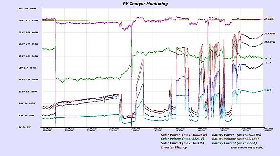
Diagramm der PV-Ladegerät-Überwachung
18A 300W 21V 15A 250W 16.8V 12A 200W 12.6V 9A 150W 8.4V 6A 100W 4.2V 3A 50W 0V 0A 0W Solar Power (max: 406.25W) Solar Voltage (max: 32.91V) Solar Current (max: 16.33A) Battery Power (max: 370.21W) Battery Voltage (max: 38.42V) Battery Current (max: 9.66A) Inverter Efficiency Latest values not to scale
in „MPP Tracker Optimierung“ · Analoge Elektronik und Schaltungstechnik · · Screenshots
-
PDF
L298.pdf
L298 DIM. mm inch MIN. TYP. MAX. MIN. TYP. MAX. OUTLINE AND MECHANICAL DATA A 5 0.197 B 2.65 0.104 C 1.6 0.063 E 0.49 0.55 0.019 0.022 F 0.66 0.75 0.026 0.030 G 1.14 1.27 1.4 0.045 0.050 0.055 G1 17.57 17.78 17.91 0.692 0.700 0.705
in „Probleme mit L298“ · Analoge Elektronik und Schaltungstechnik ·
-
PDF
l298_1_.pdf
L298 DIM. mm inch MIN. TYP. MAX. MIN. TYP. MAX. OUTLINE AND MECHANICAL DATA A 5 0.197 B 2.65 0.104 C 1.6 0.063 E 0.49 0.55 0.019 0.022 F 0.66 0.75 0.026 0.030 G 1.14 1.27 1.4 0.045 0.050 0.055 G1 17.57 17.78 17.91 0.692 0.700 0.705
in „L298 Treiber parallel schalten?“ · Analoge Elektronik und Schaltungstechnik ·
-
PDF
0900766b80c5a119.pdf
Soldering Tips for WP 80, WSP 80, FE 75 and MPR 80 Order No. Model Description Width A Thickness B max.LengthL Price (€) 005 44 494 99 LT 1SC Chisel tip, single packaged 0,4 mm 0,15 mm 15,0 mm 4,25 005 44 494 00 LT 1SC Chisel tip, bulk 0,4 mm 0,15 mm 15,0 mm 3,95 005 44 437 99 LT H Chisel tip, single
in „Flussmittel-Paste oder Flüssigkeit zum SMD-Löten“ · Platinen ·
-
PDF
LT1014.pdf
Precision Specs It is no longer necessary to compromise specifications, Guaranteed Offset Voltage 150 V Max. whilesavingboardspaceandcost,ascomparedtosingle Guaranteed Low Drift 2 V/°C Max. operational amplifiers. Guaranteed Offset Current 0.8nA Max. Guaranteed High Gain TheLT1014’slowoffsetvoltageof50 V,
in „Unterschied beim LT1014 ?“ · Mikrocontroller und Digitale Elektronik ·
-
PDF
LCW_CQ7P.CC.pdf
mA (max.) VF 3.5 V 3) page 22) Reverse Voltage Sperrspannung 3)Seite 23 I = 20 mA (max.) V 1.2 V R R Wärmewiderstand Thermal resistance Sperrschicht/Lötpad (typ.) Rth el JS 7 K/W Junction/solder point (max.
-
PDF
MA406H.pdf
resistance R 1 As per below table Operable temperature range, DL=100µW Shunt capacitance C 0 5.0pF max. Insulation resistance IR 500 MΩ min. Aging fa ±1ppm/year max. Ta=25˚C ±1˚C, DL=100µW Three drops on a hard wooden board from 75 cm or Shock resistance S. R. ±1ppm max. excitation test with 3000G x
in „Quarz anschwingen AT89S8253?“ · Mikrocontroller und Digitale Elektronik ·
-
Datei
avr.h
SMALL_REGISTER_CLASSES 1 #define CLASS_LIKELY_SPILLED_P(c) class_likely_spilled_p(c) #define CLASS_MAX_NREGS(CLASS, MODE) class_max_nregs (CLASS, MODE) #define CONST_OK_FOR_LETTER_P(VALUE, C) \ ((C) == 'I' ? (VALUE) >= 0 && (VALUE) <= 63 : \ (C) == 'J' ? (VALUE) <= 0 && (VALUE) >= -63: \ (C) == 'K' ?
in „ATtiny24 - ISR wird nie gerufen __vectors> fehlt“ · Mikrocontroller und Digitale Elektronik ·
-
PDF
heds-1300.pdf
Reverse LED Input Voltage Vr 1200 2.5 V 1300 5.0 V Photodiode Bias Vd 1200 -0.3 20 V 5 (Id = 100 A max) 1300 -0.3 20 V 5 Notes: 1. Caution: The thermal constraints of the acrylic lens will not permit the use of conventional wave soldering procedures. The typical preheat and post-cleaning temperatures
in „Kugelschreiber mit Barcodescanner bei Pollin“ · Mikrocontroller und Digitale Elektronik ·
-
PDF
LT1019.pdf
25°C. VIN 15V, I OUT = 0 unless otherwise noted. LT1019A LT1019 SYMBOL PARAMETER CONDITIONS MIN TYP MAX MIN TYP MAX UNITS Output Voltage Tolerance 0.02 0.05 0.02 0.2 % TC Output Voltage LT1019C (0°C to 70°C) ● 3 5 5 20 ppm/°C Temperature Coefficient LT1019I (–40°C to 85°C) ● 3 10 5 20 ppm/°C (Note 3)
in „Hochgenaue 2.5V Referenz“ · Mikrocontroller und Digitale Elektronik ·
-
PDF
LT1006.pdf
LTC DWG # 05-08-1320) .335 – .370 (8.509 – 9.398) DIA .305 – .335 (7.747 – 8.509) .040 (1.016) .050 MAX (1.270) .165 – .185 MAX (4.191 – 4.699) REFERENCE SEATING PLANE PLANE GAUGE PLANE .500 – .750 .010 – .045* (12.700 – 19.050) (0.254 – 1.143) .016 – .021** (0.406 – 0.533) .027 – .045 (0.686 – 1.143)
in „Probleme mit Peakdetector“ · Mikrocontroller und Digitale Elektronik ·
-
PDF
sct2210.pdf
chip is limited by its package and ambient temperature. The maximum allowable power dissipation P D(max)is determined by P D(max)(Tj(max)T a/R th(j-a)ere T j(max)maximum chip junction temperature, usually considered as 150℃, T : ambaent temperature, R th(j-a)hermal resistance of the package. The relationship
in „[V] 50 x 16bit LED-Konstantstrom-Schieberegister, SCT2210CSTG“ · Markt ·
-
PDF
tda7375.pdf
L = 2 12 W P O max Max. Output Power (***) VS = 14.4V, Bridge 36 40 W P O EIAJ EIAJ Output Power (***) VS= 13.7V, Bridge 32 35 W THD Distortion RL = 4 Single Ended, P = 0.1 to 4W 0.02 % O Bridge, O = 0.1 to 10W 0.03 0.3
in „SCHALTUNGS-problem“ · Mikrocontroller und Digitale Elektronik ·
-
PDF
tda7375.pdf
L = 2 12 W P O max Max. Output Power (***) VS = 14.4V, Bridge 36 40 W P O EIAJ EIAJ Output Power (***) VS= 13.7V, Bridge 32 35 W THD Distortion RL = 4 Single Ended, P = 0.1 to 4W 0.02 % O Bridge, O = 0.1 to 10W 0.03 0.3
in „END-VERSTÄRKER probs“ · Analoge Elektronik und Schaltungstechnik ·
-
PDF
10134fd.pdf
Precision Specs It is no longer necessary to compromise specifications, n Guaranteed Offset Voltage: 150µV Max whilesavingboardspaceandcost,ascomparedtosingle n Guaranteed Low Drift: 2µV/°C Max operational amplifiers. n Guaranteed Offset Current: 0.8nA Max TheLT1014’slowoffsetvoltageof50µV,driftof0.3µV/°C, n
in „LT1013 Unterschied D und P Package“ · Analoge Elektronik und Schaltungstechnik ·
-
PDF
MAX306-MAX307.pdf
Guaranteed Charge Injection, <10pC +85°C) and fast switching speeds (t TRANS less than / 250ns). The MAX306 is a single-ended 1-of-16 device, ♦ I NO(OFF) Leakage <2.5nA at +85°C M ♦ I COM(OFF) Leakage <20nA at +85°C and the MAX307 is a differential 2-of-8 device. ♦ ESD Protection >2000V A The MAX306/MAX307
in „Welche Spannung kann der Multiplexer MAX307 schalten?“ · Analoge Elektronik und Schaltungstechnik ·
-
 Bild
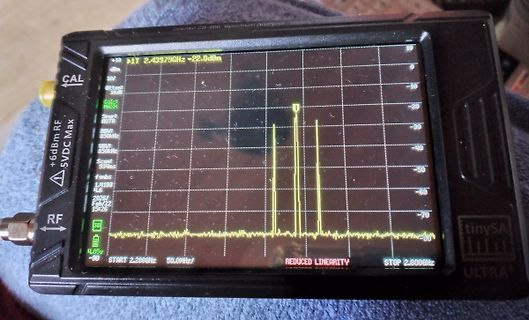
Handheld Spektrumanalysator mit Frequenzanzeige
Zeenk ZS-406 Spectrum Analyzer +10 dBm RF 5VDC Max CAL Atten: 10dB Calc: MAX RBW: 850kHz VBW: 850kHz Span: 93ms 1.4193 GHz 2.43979GHz -22.8dBm REDUCED LINEARITY START 2.200GHz 50.0MHz/ STOP 2.600GHz tinySA ULTRA
in „Handbuch Tinysa-Ultra - Wo?“ · HF, Funk und Felder · · Fotos
-
PDF
d_4490B_4490BS_MIN.pdf
2 Anschlusswiderstand, Phase-Phase R 0,237 0,445 0,720 0,690 1,340 2,130 Ω 3 Abgabeleistung 1) P2 max. 201 201 200 207 210 212 W 4 Wirkungsgrad η max. 86 86 86 85 85 86 % 5 Leerlaufdrehzahl no 9 550 10 450 11 000 5 450 5 790 6 060 rpm 6 Leerlaufstrom (bei Wellen ø 6,0 mm) Io 0,554 0,432 0,354 0,217
in „Wärmeentwicklung Brushless-Motor“ · Mikrocontroller und Digitale Elektronik ·
-
PDF
36ddedx.pdf
TYPICAL CASE SPACING WEIGHT CODE D L D L P TERMINAL M ± 0.016 (0.4) (g) ± 0.032 (0.8) ± 0.063 (1.6) (Max.) (Max.) H (Max.) AN 1.375 (35.0) 1.625 (41.0) 1.453 (36.9) 1.750 (44.5) 1.849 (47.0) 0.500 (12.7) 43.0 AY 1.375 (35.0) 1.875 (48.0) 1.453 (36.9) 2.000 (50.8) 1.099 (53.3) 0.500 (12.7) 54.0 AA 1.375
in „Unterschied Bauform "kleiner Elko" "großer Elko"“ · Analoge Elektronik und Schaltungstechnik ·
-
PDF
ag172d.pdf
067G305V479 7 4.7uF 20% 50V CN405 088G 35315F H D-SUB 15PIN CN405 088G 35315F HJ SOC SUBD H 15P F CN406 088G 35424F H DV1 CONNECTOR 24PIN CN406 088G 35424FHCJ DVI 24PIN X401 093G 22 53 CRYSTAL 14.318MHzHC-49US X401 093G 22 53 H 14.31818MHZ/30PF/49US AIC780KC6HZP MAIN BOARD CN004 033G3802 2H WAFER 2P RIGHT
in „Geplatzte 25V-Elkos im 12V-Netzteil gegen 16V Low ESR austauschen?“ · Analoge Elektronik und Schaltungstechnik ·
-
PDF
sensata-acw4-tcw4-canopen-position-sensor-user-manual.pdf
2100h: Transmission Rate Object 2101h: Node Number 6. Encoder-specific objects 6000h to 9FFFh (DS 406)............................................................................22 Object 6000h: Operating Parameters Object 6001h: Measuring Units per revolution Object 6002h: Total measuring range in
in „Hilfe mit (fehlerhafter?) EDS-Datei“ · Softwareentwicklung ·

