-
PDF
PCA9515_NXP.pdf
) dated 2003 Oct 03 PCA9515_5 20020513 Product data 853-2223 28185 PCA9515_4 (9397 750 09814) dated 2002 May 13 PCA9515_4 20020301 Product data 853-2223 27802 PCA9515_3 (9397 750 09512) PCA9515_3 20010307 Product specification 853-2223 25782 PCA9515_2 (9397 750 08127) PCA9515_2 20001201 Product specification 853-2223 25138 PCA9515_1 (9397 750 07852) PCA9515_1 20001113 Product specification 853-2223 25005 - (9397 750 07757) PCA9515_9 © NXP B.V
in „I2C Repaeter PCA9515A“ · Mikrocontroller und Digitale Elektronik ·
-
PDF
AN255_I2C__SMBus_REPEATERS_HUBS_AND_EXPANDERS.pdf
PCA9515 PCA9516 PCA9518 P82B715 P82B96 DIP Tube - - - P82B715PN P82B96PN Tube PCA9515D PCA9516D PCA9518D P82B715TD P82B96TD SO T & R PCA9515D-T PCA9516D-T PCA9518D-T P82B715TD-T P82B96TD-T TSSOP Tube -
in „SPI oder TWI“ · Mikrocontroller und Digitale Elektronik ·
-
PDF
AN255.pdf
PCA9515 PCA9516 PCA9518 P82B715 P82B96 DIP Tube - - - P82B715PN P82B96PN Tube PCA9515D PCA9516D PCA9518D P82B715TD P82B96TD SO T & R PCA9515D-T PCA9516D-T PCA9518D-T P82B715TD-T P82B96TD-T TSSOP Tube -
in „50 X LM75 an ATMEGA16?“ · Mikrocontroller und Digitale Elektronik ·
-
PDF
an10160.pdf
that prevents glitching the I C data and clock lines. 2 2. Question: We are passing signals from a PCA9515 through the PCA9544. On the I C bus lines, we are using a 1.3 kΩ pull-up resistor to 3.3 V on the PCA9515 side of the pass transistor and a 20 kΩ pull up resistor to 3.3 V on the other. We see a
in „Bussystem mit AVR für Baugruppenträger“ · Mikrocontroller und Digitale Elektronik ·
-
PDF
an10160.pdf
that prevents glitching the I C data and clock lines. 2 2. Question: We are passing signals from a PCA9515 through the PCA9544. On the I C bus lines, we are using a 1.3 kΩ pull-up resistor to 3.3 V on the PCA9515 side of the pass transistor and a 20 kΩ pull up resistor to 3.3 V on the other. We see a
in „18 x SHT11 an welchem Mikrocontroller“ · Mikrocontroller und Digitale Elektronik ·
-
PDF
AN10216.pdf
different hubs. That is not i2eal and limits the designers’ ability to expand their I C Bus repeater (PCA9515) and Hub (PCA9516) I C bus. The PCA9515 and the PCA9516 can only be used one device (either the PCA9515 or PCA9516) per system since low levels will not be transmitted through PCA the second device
in „AVR TWI: Hängt nach dem Flaschen“ · Mikrocontroller und Digitale Elektronik ·
-
 Bild
Bild
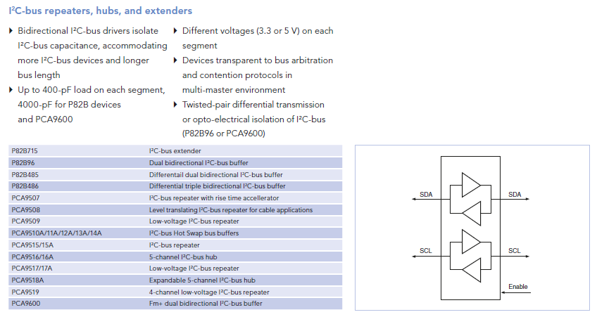
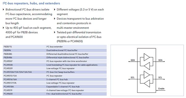
Übersicht I2C-Bus Repeater, Hubs und Extender
repeater with rise time accelerator PCA9508 Level translating I2C-bus repeater for cable applications PCA9509 Low-voltage I2C-bus repeater PCA9510A/12A/13A/14A I2C-bus Hot Swap bus buffers PCA9515/15A I2C-bus repeater PCA9516/16A 5-channel I2C-bus hub PCA9517/17A Low-voltage I2C-bus repeater PCA9518A Expandable 5-channel I2C-bus hub PCA9519 4-channel low-voltage I2C-bus repeater PCA9600 Fm+ dual bidirectional I2C-bus buffer SDA SCL Enable
in „Ansteuerung einer Anzeigetafel - Federal Vama Traffic Storm“ · Fahrzeugelektronik · · Screenshots
-
PDF
PCA9517_Level_Shifter_I2C.pdf
accommodates smaller voltage swings of lower voltage logic. The static offset design of the B-side PCA9517 I/O drivers prevent them from being connected to another device that has rise time accelerator including the PCA9510, PCA9511, PCA9512, PCA9513, PCA9514, PCA9515A, PCA9516A, PCA9517 (B-side), or
in „I2C Taktsignal“ · Mikrocontroller und Digitale Elektronik ·
-
 Bild
Bild
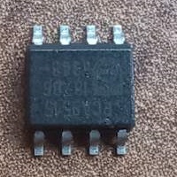
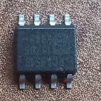
Elektronisches Bauteil in SOIC-Gehäuse
PCA9516
in „I2C Repaeter PCA9515A“ · Mikrocontroller und Digitale Elektronik · · Fotos
-
PDF
notes_82b96.pdf
without exceeding the 400 pF specs. A total of 400 pF would be allowed on each side of the interface. PCA9515 can also be used to link (just) two standard 400pF busses like this. It IS allowed to interconnect, say, 10 of these interfaces together on the ‘new’ bus formed by the linked TxD/RxD pins and thus
in „18 x SHT11 an welchem Mikrocontroller“ · Mikrocontroller und Digitale Elektronik ·
-
PDF
notes_82b96.pdf
without exceeding the 400 pF specs. A total of 400 pF would be allowed on each side of the interface. PCA9515 can also be used to link (just) two standard 400pF busses like this. It IS allowed to interconnect, say, 10 of these interfaces together on the ‘new’ bus formed by the linked TxD/RxD pins and thus
in „I²C galvanisch trennen“ · Mikrocontroller und Digitale Elektronik ·
-
PDF
Bus_Buffer_P82B96_4_datasheet.pdf
conversion of I C SDA or SCL signals to multi-drop differential bus hardware, e.g., via compatible PCA82C250. voltage level. If this special “buffered low” is applied to the Sx/Sy of another P82B96 that second P82B96 will not recognize it as a Interfaces with Opto-couplers to provide Opto isolation between
in „I2C EEPROM Störung bei 15m mit BusBuffer P82B96“ · Mikrocontroller und Digitale Elektronik ·
-
PDF
Bus_Buffer_P82B96_4_datasheet.pdf
conversion of I C SDA or SCL signals to multi-drop differential bus hardware, e.g., via compatible PCA82C250. voltage level. If this special “buffered low” is applied to the Sx/Sy of another P82B96 that second P82B96 will not recognize it as a Interfaces with Opto-couplers to provide Opto isolation between
in „I2C EEPROM Störung bei 15m mit BusBuffer P82B96“ · Mikrocontroller und Digitale Elektronik ·
-
PDF
P82B86.pdf
conversion of I C SDA or SCL signals to multi-drop differential bus hardware, e.g., via compatible PCA82C250. voltage level. If this special “buffered low” is applied to the Sx/Sy of another P82B96 that second P82B96 will not recognize it as a Interfaces with Opto-couplers to provide Opto isolation between
in „Wie Die Richtung bei einem 2-Draht-Bus erkennen?“ · Mikrocontroller und Digitale Elektronik ·
-
PDF
Bus_Buffer_P82B96_4_datasheet.pdf
conversion of I C SDA or SCL signals to multi-drop differential bus hardware, e.g., via compatible PCA82C250. voltage level. If this special “buffered low” is applied to the Sx/Sy of another P82B96 that second P82B96 will not recognize it as a Interfaces with Opto-couplers to provide Opto isolation between
in „Kondensatoren bei I2C + BusBuffer, wofür?“ · Mikrocontroller und Digitale Elektronik ·
-
PDF
Bus_Buffer_P82B96_4_datasheet.pdf
conversion of I C SDA or SCL signals to multi-drop differential bus hardware, e.g., via compatible PCA82C250. voltage level. If this special “buffered low” is applied to the Sx/Sy of another P82B96 that second P82B96 will not recognize it as a Interfaces with Opto-couplers to provide Opto isolation between
in „Kondensatoren bei I2C + BusBuffer, wofür?“ · Mikrocontroller und Digitale Elektronik ·
-
PDF
TCA9406_I2C_translator.pdf
and fast mode plus I C-bus devices in additional to SMBus. The TCA9406 is not a bus buffer like the PCA9515A and PCA9517. It provides both level translation and physically isolates the capacitance to either side of the bus when both sides are connected. The I offfeature can be utilized to isolate the
in „I2C translator tri-state“ · Mikrocontroller und Digitale Elektronik ·
-
PDF
P82B96_7.pdf
of I C-bus SDA or SCL signals to multi-drop differential bus hardware, for example, via compatible PCA82C250 n Interfaces with opto-couplers to provide opto-isolation between I C-bus nodes up to 400 kHz. 4. Ordering information Table 1. Ordering information Type number Package Name Description Version
in „18 x SHT11 an welchem Mikrocontroller“ · Mikrocontroller und Digitale Elektronik ·
-
PDF
UM10204-user-manual.pdf
the PCA9517 bus buffer or the PCA9546A switch. • Switched pull-up circuit (Section 7.2.4): A switched pull-up circuit can be used to accelerate rising edges by switching a low value pull-up alternately in and
in „PCA9507, Slaves auf beiden Seiten“ · Mikrocontroller und Digitale Elektronik ·
-
PDF
I2C-bus_specification_2014.pdf
the PCA9517 bus buffer or the PCA9546A switch. • Switched pull-up circuit (Section 7.2.4): A switched pull-up circuit can be used to accelerate rising edges by switching a low value pull-up alternately in and
in „I2C Pullup bei vielen I2C Devices“ · Mikrocontroller und Digitale Elektronik ·
-
PDF
I2C-bus_specification_2014.pdf
the PCA9517 bus buffer or the PCA9546A switch. • Switched pull-up circuit (Section 7.2.4): A switched pull-up circuit can be used to accelerate rising edges by switching a low value pull-up alternately in and
in „Doppelte Pull-Ups bei i2c?“ · Mikrocontroller und Digitale Elektronik ·
-
PDF
I2C-bus_specification_2014.pdf
the PCA9517 bus buffer or the PCA9546A switch. • Switched pull-up circuit (Section 7.2.4): A switched pull-up circuit can be used to accelerate rising edges by switching a low value pull-up alternately in and
in „MCP23017 friert ein, stürzt ab“ · Mikrocontroller und Digitale Elektronik ·
-
PDF
I2C_Ref_UM10204.pdf
the PCA9517 bus buffer or the PCA9546A switch. • Switched pull-up circuit (Section 7.2.4): A switched pull-up circuit can be used to accelerate rising edges by switching a low value pull-up alternately in and
in „TWI Bus hängt sich auf“ · Mikrocontroller und Digitale Elektronik ·
-
PDF
I2C-bus_specification_2014.pdf
the PCA9517 bus buffer or the PCA9546A switch. • Switched pull-up circuit (Section 7.2.4): A switched pull-up circuit can be used to accelerate rising edges by switching a low value pull-up alternately in and
in „Wodtke HP-S5 HP Er3 EEPROM Schreib-/Lesefehler“ · Haus & Smart Home ·
-
PDF
o_ring_material_guide_ger.pdf
C318 - - A A B B A A U Freon MF - B U U B - B B U Glykokoll (Aminoessigsäure, U U A A A U B B U Freon PCA - A A U B - A A U Leimsüß) Freon TA - A A A U - A A A Glykolsäure (Hydroxyessigsäure)U U B A B A A A A Freon TC - A A B A - A A U Grubengas (Methan) A U B B A A A A A Freon TF - A A U A U A A U Freon
-
PDF
philips_chassis_qfu2.1e_la.pdf
which have the same CTN (Commercial Type 6 = play 16 : 9 format, 12 = play 4 : 3 Number; e.g. 28PW9515/12) but which have a different B.O.M. format number. AARA Automatic Aspect Ratio Adaptation: By looking at the third digit of the serial number, one can algorithm that adapts aspect ratio to identify
in „Netzteil Philips LED TV reparieren??“ · Analoge Elektronik und Schaltungstechnik ·