-
Datei
IIC.C
,PCF8583_Monat); empf &= 0xE0;s |= empf; IIC_PCF8583_write (Adresse,PCF8583_Monat,s); } /* #################################################################################### void IIC_PCF8583_WWD (int Adresse
-
Datei
IIC.C
,PCF8583_Monat); empf &= 0xE0;s |= empf; IIC_PCF8583_write (Adresse,PCF8583_Monat,s); } /* #################################################################################### void IIC_PCF8583_WWD (int Adresse
in „IIc Programmierung“ · Mikrocontroller und Digitale Elektronik ·
-
Datei
iic.c
,PCF8583_Monat); empf &= 0xE0;s |= empf; IIC_PCF8583_write (Adresse,PCF8583_Monat,s); } /* #################################################################################### void IIC_PCF8583_WWD (int Adresse
in „iic Programmirung2“ · Mikrocontroller und Digitale Elektronik ·
-
Datei
iic.c
,PCF8583_Monat); empf &= 0xE0;s |= empf; IIC_PCF8583_write (Adresse,PCF8583_Monat,s); } /* #################################################################################### void IIC_PCF8583_WWD (int Adresse
in „I2c Programmierung“ · Mikrocontroller und Digitale Elektronik ·
-
Datei
IIC.C
,PCF8583_Monat); empf &= 0xE0;s |= empf; IIC_PCF8583_write (Adresse,PCF8583_Monat,s); } /* #################################################################################### void IIC_PCF8583_WWD (int Adresse
in „I2c Programmierung“ · Mikrocontroller und Digitale Elektronik ·
-
Datei
twi_lib.h
#define PCF8583_MonthReg 0x06 // Dow, 10Mon + 1Mon #define PCF8583_TimerReg 0x07 // Timer #define PCF8583_AlarmReg 0x08 // Alarm Control Register #define PCF8583_DezAlaReg 0x09 // #define PCF8583_SecAlaReg 0x0A // #define PCF8583_MinAlaReg 0x0B // #define PCF8583_HorAlaReg 0x0C // #define PCF8583_DatAlaReg 0x0D // #define PCF8583_MonAlaReg 0x0E // #define PCF8583_TimAlaReg 0x0F // #define PCF8583_YearReg 0x10 // HS defined
in „TWI MUX per SW an einem Port“ · Mikrocontroller und Digitale Elektronik ·
-
Datei
twi_lib.c
is filled with data TWI_PCF8583_ByteWrite( Addr_TCCVVVBBB, PCF8583_StatusReg, PCF8583_StopCountingBit ); // Stop advancing clock twi1.NrBytesToTransmit = 3; twi1.NrBytesToReceive = 0; twi1.TxRxBuffer[0] = PCF8583_DayReg; // Address
in „TWI MUX per SW an einem Port“ · Mikrocontroller und Digitale Elektronik ·
-
Datei
main.c
DATETIME_T *DT){ /*************************************************************************/ i2c_start(PCF8583_WR_ADR); i2c_write(PCF8583_CTRL_STATUS_REG); i2c_write(PCF8583_STOP_COUNTING | PCF8583_MASK); //Stop counting //Time i2c_write(0x00); //1/100 Seconds i2c_write(BIN2BCD(DT->sec)); i2c_write(BIN2BCD
in „PCF 8583 läuft zu langsam“ · Mikrocontroller und Digitale Elektronik ·
-
Datei
tst_PCF8583.c
uchar xdata ucResRAM[12]={11}; main(){ uchar ucError; // Check is chip valid ucError = uc_I2C_Dev(I2C_PCF8583); // Device was found if (ucError == OK){ //1. set time with AM/PM flag ucError = uc_Data2I2C(I2C_PCF8583, TM_HSEC , ucTime); //2. write text into RAM ucError = uc_Data2I2C(I2C_PCF8583, 0x10 , aucInfo); //3. read text from RAM ucError = uc_I2C2Data(I2C_PCF8583, 0x10 , ucResRAM); //4. read time from RTC ucError = uc_I2C2Data(I2C_PCF8583, TM_HSEC , ucResTime); //5. set timer ucALTime[0] = 2; // length of bytes ucALTime[1] = 0x40; // set counter to 64 ucALTime
in „Ansteuerung eines PCF8583“ · Mikrocontroller und Digitale Elektronik ·
-
PDF
TWI_logger_readme.pdf
können Datum, Uhrzeit und Messintervall eingegeben werden, der Mega88 reicht die Daten via TWI an den PCF8583 weiter. Nach dem Start des Loggens geht der Mega88 in den Powerdown-Modus, der Controller und die TWI-Komponenten haben dieser Phase eine sehr geringe Stromaufnahme. Der PCF8583 läuft als Clock
in „TWI-Datenlogger mit M88, PCF8583, AT24C512 (+ DS18B20) für den Batteriebetrieb“ · Projekte & Code ·
-
PDF
PCF8583.pdf
Clock/calendar with 240 × 8-bit RAM PCF8583 5 BLOCK DIAGRAM handbook, full pagewidth 1 DIVIDER control/status 00 OSCI PCF8583 1 : 256 100 Hz 2 OSCILLATOR OR hundredth of a second01 OSCO 32.768 kHz 100 : 128 seconds 7 minutes INT hours 8 VDD
in „RTC PCF8583 einen Interrupt ausloesen“ · Mikrocontroller und Digitale Elektronik ·
-
PDF
PCF8583_5_rtc_real_time_clock.pdf
Clock/calendar with 240 × 8-bit RAM PCF8583 5 BLOCK DIAGRAM handbook, full pagewidth 1 DIVIDER control/status 00 OSCI PCF8583 1 : 256 100 Hz 2 OSCILLATOR OR hundredth of a second01 OSCO 32.768 kHz 100 : 128 seconds 7 minutes INT hours 8 VDD
-
PDF
PCF8583P.pdf
Clock/calendar with 240 × 8-bit RAM PCF8583 5 BLOCK DIAGRAM handbook, full pagewidth 1 DIVIDER control/status 00 OSCI PCF8583 1 : 256 100 Hz 2 OSCILLATOR OR hundredth of a second01 OSCO 32.768 kHz 100 : 128 seconds 7 minutes INT hours 8 VDD
-
PDF
PCF8583_5.pdf
Clock/calendar with 240 × 8-bit RAM PCF8583 5 BLOCK DIAGRAM handbook, full pagewidth 1 DIVIDER control/status 00 OSCI PCF8583 1 : 256 100 Hz 2 OSCILLATOR OR hundredth of a second01 OSCO 32.768 kHz 100 : 128 seconds 7 minutes INT hours 8 VDD
in „PCF8583: Welche Genauigkeit kann ìch erwarten?“ · Mikrocontroller und Digitale Elektronik ·
-
Datei
rtc.cc
error_t Clock::from_rtc() { uint8_t buf[6]; uint8_t ybuf[1]; uint8_t addr, rc; addr = 1; rc = i2c_read(PCF8583, &addr, 1, buf, 6); if (rc == I2C_SUCCESS) { addr = RTC_YEAR; rc = i2c_read(PCF8583, &addr, 1, ybuf, 1); } if (rc != I2C_SUCCESS) { return ERROR_RTC + rc; } // we only have 2 clocked bits for the
in „Real Time Clock“ · Mikrocontroller und Digitale Elektronik ·
-
Datei
PCF8583alsCounter.txt
= 0 '------------------------------------------- Locate 1 , 1 Lcd "Test Zähler" Locate 2 , 1 Lcd "PCF8583" Locate 3 , 1 Lcd "Timer0" Locate 4 , 1 Lcd "Timer1" Timer0 = 240 'Counter vorbesetzen Timer1 = 65525 Call Set_counter 'inizialisieren PCF8283 als Counter und auf 0 Waitms 10 Do 'Endlosschleife Portd.4 = 1 'Port als Testzählerinput Waitms 10 Portd.4 = 0 Call Get_counter() 'hole Werte aus pcf8583 Locate 2 , 9 Lcd P7 Locate 3 , 9 Lcd T0 Locate 4 , 9 Lcd T1 Wait 1 'Zähler pro Sec um 1 erhöhen Loop Sub Set_counter() 'PCF einstellen I2cstart 'generate start I2cwbyte &HA0 'write addres of PCF8583
in „PCF8283 als Zähler“ · Mikrocontroller und Digitale Elektronik ·
-
Datei
uhr.c
Port D (von D auf C geändert) #define SCL_PORT PORTC // SCL Port D (von D auf C geändert) #define PCF8583 0xA0 // device address of PCF8583 A0 schreibe IIC-Adresse (PCF 8583) - Eingabe 02 schreibe Register-Adresse (Sekunden) A1 schreibe IIC-Adresse (PCF 8583) lesen - Ausgabe */ void gettime(char* time
in „Zeit auslesen PCF8583-Atmega8“ · Mikrocontroller und Digitale Elektronik ·
-
Datei
Clock_eigen2.bas
------------------ ' Copyright 1998-2002 MCS Electronics ' CLOCK.BAS 'This AN shows how to use the PCF8583 I2C clock device 'The PCF8583 is a PHILIPS device. Look at the datasheet for more details 'I have used the STK200 to test the program with a 8515 '-----------------------------------------------
in „Ansteuerung eines PCF8583“ · Mikrocontroller und Digitale Elektronik ·
-
PDF
AN_pcf8563-73-83-93_real_time_clock.pdf
circuitry technologies The focus of this paper is on the latest device from Philips Semiconductors the PCF8563. Never the less comparisons to the other devices are done where appropriate. 1 2. Comparison Features PCF8563 PCF8573 PCF8583 PCF8593 I C-bus interface speed 400kHz 100kHz 100kHz 100kHz Scratch
in „I2C Buslaenge ueber 5m?“ · Mikrocontroller und Digitale Elektronik ·
-
PDF
PCF8563jingdu_en.pdf
circuitry technologies The focus of this paper is on the latest device from Philips Semiconductors the PCF8563. Never the less comparisons to the other devices are done where appropriate. 1 2. Comparison Features PCF8563 PCF8573 PCF8583 PCF8593 I C-bus interface speed 400kHz 100kHz 100kHz 100kHz Scratch
in „CP/M auf ATmega88“ · Mikrocontroller und Digitale Elektronik ·
-
Datei
Clock.bas
------------------ ' Copyright 1998-2002 MCS Electronics ' CLOCK.BAS 'This AN shows how to use the PCF8583 I2C clock device 'The PCF8583 is a PHILIPS device. Look at the datasheet for more details 'I have used the STK200 to test the program with a 8515 '-----------------------------------------------
in „Timer, Wecker etc“ · Mikrocontroller und Digitale Elektronik ·
-
Datei
Clock_eigen3.bas
------------------ ' Copyright 1998-2002 MCS Electronics ' CLOCK.BAS 'This AN shows how to use the PCF8583 I2C clock device 'The PCF8583 is a PHILIPS device. Look at the datasheet for more details 'I have used the STK200 to test the program with a 8515 '-----------------------------------------------
in „Ansteuerung eines PCF8583“ · Mikrocontroller und Digitale Elektronik ·
-
PDF
I2C-Bus_Adressliste__Elektronik-Magazin.pdf
PCF8571 PCF8580 PCF8580 PCF8580 PCF8580 PCF8580 PCF8580 PCF8580 PCF8580 PCF8581 PCF8581 PCF8581 PCF8581 PCF8581 PCF8581 PCF8581 PCF8581 PCF8582 PCF8582 PCF8582 PCF8582 PCF8582 PCF8582 PCF8582 PCF8582 PCF8583 PCF8583 1011 SAA7199 SAA7199 TDA8416 TDA2518 PCA8510 SAA7186 SAA9065 SAA7152 SAA7186 PCA8516 PCF8570 PCF8570 PCF8570 PCF8570 PCF8570 PCF8570 PCF8570 PCF8570 1100 TSA5510 TSA5510 TSA5510 TSA5510 TSA5510
in „PCF8574/PCF8574A Adressierung“ · Mikrocontroller und Digitale Elektronik ·
-
Datei
Clock_eigen4.bas
------------------ ' Copyright 1998-2002 MCS Electronics ' CLOCK.BAS 'This AN shows how to use the PCF8583 I2C clock device 'The PCF8583 is a PHILIPS device. Look at the datasheet for more details 'I have used the STK200 to test the program with a 8515 '-----------------------------------------------
in „Ansteuerung eines PCF8583“ · Mikrocontroller und Digitale Elektronik ·
-
Datei
unilib.h
# int pcf8583_get_hour(unsigned char devaddr); //####################################################################### //# read day # //####################################################################### int pcf8583_get_day(unsigned char devaddr); //####################################################################### //# read weekday # //###################################################################
in „Bauen von Libs - Anhängigkeiten“ · Mikrocontroller und Digitale Elektronik ·
-
PDF
AN10652.pdf
these RTCs can be powered by a very small battery or a small super-cap. The RTCs most similar to the PCF8563 are PCA8565, PCF8583 and PCF8593. Besides this range the product line includes the PCA2125 and will soon be extended with PCF2124 and PCF2128 (release end of 2007). Thus the product line includes
in „Frage zum Counter der RTC PCF8563“ · Mikrocontroller und Digitale Elektronik ·
-
PDF
PCF8563-Improve-Clock.pdf
these RTCs can be powered by a very small battery or a small super-cap. The RTCs most similar to the PCF8563 are PCA8565, PCF8583 and PCF8593. Besides this range the product line includes the PCA2125 and will soon be extended with PCF2124 and PCF2128 (release end of 2007). Thus the product line includes
in „Stromsparender Sekundentakt“ · Mikrocontroller und Digitale Elektronik ·
-
Datei
pcf.txt
RTC_INI () { I2C_BUS_START (); I2C_W (0xA0); // zum lesen adressieren I2C_W (0x00); // Adresse im pcf 8583 I2C_W (0x80); // 0 in das register schreiben I2C_BUS_STOPP (); I2C_BUS_START (); I2C_W (0xA0); // zum lesen adressieren I2C_W (0x02); // Adresse im pcf 8583 I2C_W (0x00); // 0 in das register schreiben
in „hilfe ! pcf 8583 + pic 16f877“ · Mikrocontroller und Digitale Elektronik ·
-
Datei
error_in_messung.c
logisch zurück - ohne die Daten selbst zu löschen void TWI_eeprom_reset(void) { twi_eeprom_adr = 0; PCF8583_write_byte(PCF_EEPROM_ADR_HIGH, 0); // gespeicherte Adresse löschen PCF8583_write_byte(PCF_EEPROM_ADR_LOW, 0); // <- Low-Byte, nicht High-Byte !!!!!!!!!!!!!!!! } // -----------------------------
in „TWI-Datenlogger mit M88, PCF8583, AT24C512 (+ DS18B20) für den Batteriebetrieb“ · Projekte & Code ·
-
PDF
RepPCF8583ByF2013.pdf
I:\IAR Embedded Workbench\430\BoardSupport\Assembly_IAR\RepPCF8583ByF2013.s43 Mittwoch, 28. September 2022 15:37 ;******************************************************************************* ; MSP430F2013 Intelligent PCF8583 Replacement with 4 Conter and 1 A
in „Fragen zum PCF8583 als Event Counter“ · Mikrocontroller und Digitale Elektronik ·
-
Datei
main.c
/* Ansteuerung einer RTC über I²C RTC : PCF8583P Phillips Atmega 16 I²C Anschlüsse: SDA PC1 SCL PC0 */ #include <avr/io.h> #include "lcd.h" #include <util/delay.h> #define F_CPU 8000000 #define TAKT 8000000UL //Systemtakt 8.0000 MHz #define AUSAD
-
PDF
FRAM_Block_D.pdf
RepPCF8583ByF2013.s43 * - Printed on 20.10.2022 07:24:57 217 ;------------------------------------------------------------------------------- 218 RSEG INFOD ; Define Flash segment 01000h ~ 0103Fh 219 ; Internal
in „Fragen zum PCF8583 als Event Counter“ · Mikrocontroller und Digitale Elektronik ·
-
Datei
PCF8583.c
byte PCF_Read_from_Ram(byte Adress) { byte data; i2c_start(); i2c_write(0xa0); i2c_write(adress); i2c_start(); i2c_write(0xa1); data = i2c_read(0); i2c_stop(); return data; } void PCF_Store_to_Ram(byte Adress, byte data) { i2c_start(); i2c_write(0xa0); i2c_write(adress); i2c_write(data); i2c_stop(); return; } int Read_min() { return hex2dec(PCF_Read_from_Ram(0x03)); } int Read_std() { return hex2dec(PCF_Read_from_Ram(0x04)&0x3F); } int Read_day() { return hex2dec(PCF_Read_from_Ram(0x05)&0x3F); } int Read_month() { return hex2dec(PCF_Read_from_Ram(0x06)&0x1F); } int Read_year() { return; }
-
Datei
master.c
:(" #endif #define MYUBRR F_CPU / 57600 / 16 - 0.5 /// busy wait loops #include <util/delay.h> /// PCF8583 RTC #define SlaveAddress 0xA0 #define SlaveWrite 0 #define SlaveRead 1 /// data #define MAX_DATA 10 int main (void) { uint8_t i; uint8_t data; char str[30]; /* ** set up serial communications */
in „atmega168: PCF8583 am TWI“ · Mikrocontroller und Digitale Elektronik ·
-
Datei
pcf8583_include.bas
' version für pcf 8583 über hardware twi -- hierzu unbedingt $lib "i2c_twi.lbx" ins hauptprogramm ' einbinden. sonst läuft twi als soft-emulation.. das bremst das ganze dann auf 40% aus. ' die automatische erkennung
in „Verstehe TWI überhaupt nicht“ · Mikrocontroller und Digitale Elektronik ·
-
PDF
PL68K12.pdf
6264-62256 mit Batteriepufferung und EPROM 2764-27512; MAX232 (optional) ser. Schnittstellentreiber PCF8583 (optional) IIC-Uhrenbaustein mit RAM ST24C02 (optional) (-4, -8) IIC-EEPROM mit 256, 512 oder 1024 bytes TL7705 Resetschaltung sowie Logik-Bausteine für Adressdekodierung, Interruptverarbeitung,
in „S: 68000/68HC000/68EC000/68001 CPUs min. 12MHz“ · Markt ·
-
PDF
PL68K12.pdf
6264-62256 mit Batteriepufferung und EPROM 2764-27512; MAX232 (optional) ser. Schnittstellentreiber PCF8583 (optional) IIC-Uhrenbaustein mit RAM ST24C02 (optional) (-4, -8) IIC-EEPROM mit 256, 512 oder 1024 bytes TL7705 Resetschaltung sowie Logik-Bausteine für Adressdekodierung, Interruptverarbeitung,
in „[S] MPU (Z80/6502/68k)“ · Markt ·
-
Datei
rotary.txt
(verbunden über Inverter mit R von RS485) ; P1.7 (über Inverter an DE von RS485) ;I2C: Echtzeituhr PCF8583T/PCF8593T, Display, LM76 ; P1.6 I2C - SDA ; P1.5 I2C - SCL ;Port - Verwendung: ;Port0: Data - Bus ;Port1: P1.0 AnalogIN0, T2 External clock input for Timer/counter2 ; P1.1 AnalogIN1, T2EX Trigger
in „8051 Projekt Rotary Encoder“ · Mikrocontroller und Digitale Elektronik ·
-
PDF
I2CselectionGUIDE.pdf
A2 A1 A0 PCF8574A 8-bit remote I/O port (I C-bus to parallel converter) 0 1 0 PCF8577C 32/64-segment LCD display driver 0 1 A0 PCF2103 LCD controller/driver 0 1 A0 PCF2104 LCD controller/driver 0 1 A0 PCF2105 LCD
in „Übersicht I2C-Adressen“ · Mikrocontroller und Digitale Elektronik ·
-
Datei
Clock_Read_an_LCD.bas
aus den PCF-Registern auszulesen Sub Clock_read 'I2cstart 'Liest die Sekunden aus der Addresse &H02 'I2cwbyte Adresw1 'I2cwbyte &H02 'I2cstart 'I2cwbyte Adresr1 'I2crbyte Seconds1 , Ack 'I2crbyte Minutes1 , Ack
-
Datei
PCF8583mitAlarmundint.bas
$lib "mcsbyte.lbx" ' use the byte lib since we do not need longs $regfile = "8535def.dat" $crystal = 7372800 $baud = 19200 Declare Sub Settime(byval S1 As Byte , Byval M1 As Byte , Byval H1 As Byte , Byval D1 As Byte , Byval Month1 As Byte) Declare Sub Setalert(byval S1 As Byte , Byval M1 As Byte , Byval H1 As Byte , Byval D1 As Byte , Byval Month1 As Byte) Declare Sub Gettime() Dim Tm(5) As Byte At &H60 Dim I As Byte , Temp As Byte Dim S As Byte At &H60 Overlay Dim M As Byte At &H61 Overlay Dim H As Byte At &H62 Overlay Dim D As Byte At &H63 Overlay Dim Month As Byte At &H64 Overlay Dim Cnt As
in „Alarm setzen im pcf8583“ · Mikrocontroller und Digitale Elektronik ·
-
PDF
Elektronik_Sortimente.pdf
2-Wire Serial EEPROM (AT24C32) ggf in DS3231 enthalten 3x Clock and calendar with 240 x 8-bit RAM (PCF8583) 5-10x 16-channel, 12-bit PWM Fm+ I2C-bus LED controller (PCA9685) 5x 16 CHANNEL LED DRIVER WITH DOT CORRECTION AND GRAYSCALE PWM CONTROL (TLC5940NT) 5x 8-bit I/O expander for I2C-bus (PCF8574,
in „Einkaufsliste für die Einrichtung eines Elektronik-Labors“ · Mikrocontroller und Digitale Elektronik ·
-
Datei
RTC_PCF_8583_LCD.asm
list p=16f876 #include <P16f876.INC> ; LCD-Uhr ; RTC PCF 8583 ; f = 16 Mhz ; Variablen festlegen w_copy equ 0x20 s_copy equ 0x21 LcdDaten equ 0x22 LcdStatus equ 0x23 loops equ 0x24 loops2 equ 0x25 HexZahl equ 0x26 Zehner equ 0x27 Einer equ 0x28 loop4ms equ
-
Datei
rtc2.cc
static void rtc_control(uint8_t ctrl) { uint8_t addr = 0; i2c_write(PCF8583, &addr, 1, &ctrl, 1); }
in „Real Time Clock“ · Mikrocontroller und Digitale Elektronik ·
-
PDF
Ausgangsstufen_Logic_IC.pdf
aufgenommen werden. Bei HIGH können nur sehr geringe Ströme entnommen werden, siehe Port-Expander PCF8574. Der Widerstandswertes des Pull-up-Widerstands darf nicht zu groß gewählt werden, da sonst zusammen mit Eingangs- und parasitären Kapazitäten die Signale verschleifen und im Extremfall nicht mehr
in „Wittig(welec) DSO W20xxA Open Source Firmware (Teil3)“ · Mikrocontroller und Digitale Elektronik ·
-
 Bild
Bild
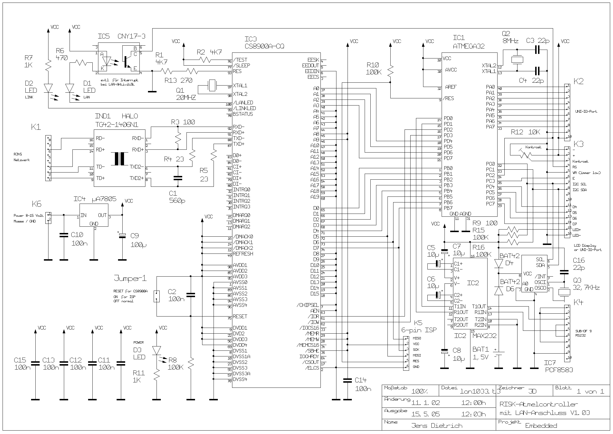
Schaltplan einer Mikrocontroller-Schaltung mit ATmega32
IC1 ATMEGA32, IC3 CS8900A-CQ, IC4 uA7805, IC7 PCF8583, K1, K2, K3, K4, K5, K6, R1 bis R30, C1 bis C16, D1 bis D3, LED, VCC, GND, RESET, ISP, UART, SPI, I2C, USB, Jumper-1, Projekt: RISIK-Atmelcontroller, Erstellt von: Jens Dietrich
in „ATMega88 an RJ45 anschließen.“ · Mikrocontroller und Digitale Elektronik · · Schaltpläne
-
Datei
PCF_8583_real_time_clock.asm
list p=16f876 #include <P16f876.INC> ; PCF 8583 rtc loops equ 0x20 loops2 equ 0x21 Datenpuffer equ 0x22 ; einstellen von RC3 & RC4 auf input bsf STATUS, RP0 ; Bank 1 movlw B'00011000' ; RC3,4 inputs iorwf TRISC, f ; + RC2=CCP1 output movlw B
-
Datei
RTC_PCF_8583_LCD5.asm
list p=16f876 #include <P16f876.INC> ; LCD-Uhr ; RTC PCF 8583 ; f = 16 Mhz ; Variablen festlegen w_copy equ 0x20 s_copy equ 0x21 LcdDaten equ 0x22 LcdStatus equ 0x23 loops equ 0x24 loops2 equ 0x25 HexZahl equ 0x26 Zehner equ 0x27 Einer equ 0x28 loop4ms equ
-
 Bild
Bild
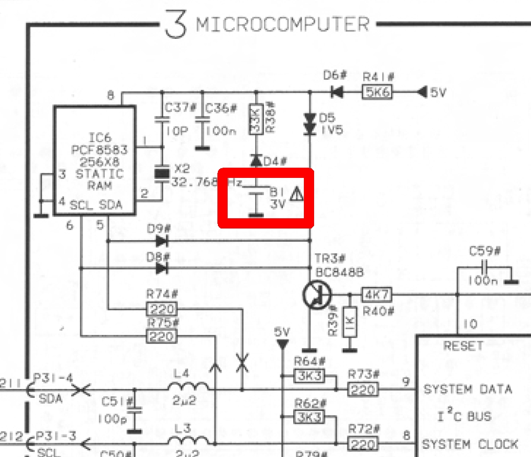
Ausschnitt eines Schaltplans
3 MICROCOMPUTER D6# R41# 5V IC6 PCF8583 256X8 3 STATIC RAM C37# C36# 10P 100n R38# 33K D5 1V X2 32.768 Hz D4# BI 3V D9# D8# TR3# BC848B C59# 100n 4K7 R40# 10 R39# 1K R74# 220 R75# 220 5V R64# 3K3 R73# 220 RESET SYSTEM DATA I2C BUS SYSTEM
in „Beosound Ouverture Radiofrequenzen“ · HF, Funk und Felder · · Schaltpläne
-
Datei
partlist.txt
IC2 AT24C512 DIL08 atmel (24.13 38.1) R0 IC3 MEGA48/88/168-AU TQFP32-08 avr-7 (39.37 20.32) R0 IC4 PCF8574T SO16W micro-philips (78.74 40.64) R180 IC6 LP2950CDT-3.3 DPACK v-reg (53.34 58.42) R90 IC7 HM51W17805 SOJ28-4 AMESYS (57.15 20.32) R180 IC8 FT232RL SSOP28 ftdichip (21.9075 14.2875) R90 JP1 JP2Q
in „CP/M auf ATmega88“ · Mikrocontroller und Digitale Elektronik ·