-
PDF
txb0104_level_shifter.pdf
ORDERING INFORMATION TA PACKAGE (1) ORDERABLE PART NUMBER TOP-SIDE MARKING UFBGA – GXU Reel of 2500 TXB0104GXUR YE04 UFBGA – ZXU (Pb-Free) Reel of 2500 TXB0104ZXUR YE04 TXB0104RGYR QFN – RGY Reel of 1000 YE04 TXB0104RGYRG4 TXB0104D –40°C to 85°C Tube of 50 TXB0104DG4 SOIC – D TXB0104 TXB0104DR Reel of 2500 TXB0104DRG4 TXB0104PWRPWR TSSOP – PW Reel of 2000 YE04 TXB0104PWRG4 (1) Package drawings, standard packing quantities, thermal data, symbolization, and PCB design guidelines are available at www.ti.com/
in „SD-Karte mit Levelshifter Problem“ · Mikrocontroller und Digitale Elektronik ·
-
PDF
zusammen.pdf
Signal für die beiden Transmitter U50/U40: Das Signal SLAVE_DIR wird zum übrigen Eingang v. U4/5(=A4) TXB0104 geschaltet. Der Ausgang U4/10(=B4) wird zum Enable Signal, RL_ENABLE Pin 4 von U50/U40. - Steuer Signal für die beiden Receiver U30/U20: DIP Switch SW1/DIP8 : Der Ausgang, Pin 16 wird zum übrigen Eingang v. U4/5(=A3) TXB0104 geschaltet. Der Ausgang U4/11(=B3)wird zum Enable Signal, RL_SLAVE Pin 4 von U30/U20. - Power OK/ POWER_FAIL Signal. A) PIN VV (40) über einen Widerstand von ca 47 mit +5Volt verbunden werden ,
-
PDF
Netzteil_Darlington_v2.pdf
N 1.65-5.5V 4 BAT54FILMY G 3 G IC3 1M AGND D VCCA ≤ VCCB MOSI_5V 5 14 VSET R1 N 7 SDI VOUTA 10 n . TXB0104 VOUTB ISET 2 0 3 DAC_CS_5V 3 CS AGND +15V C 1 - SCK_5V 4 AGND D D SCK . N 1 R - A 8 LDAC 10k 0.1% 0 8 OPA2197 - +5V_INT DAC_SHDN_5V 9 R2 k ADC_SENSE 3 IC11A AGND D SHDN 2 C 1 1 . IC4 ADC_CH1 1 -
in „„Darlington mit Opamp“-Schaltung zum Schwingen bringen/Verständnisfrage“ · Analoge Elektronik und Schaltungstechnik ·
-
PDF
txs0104e.pdf
where an open-drain driver is connected to the data I/Os. The TXS0104E device can also be used in applications where a push-pull driver is connected to the data I/Os, but the TXB0104 device might be a better option for such push- pull applications. 9.2 Typical Application
in „[V] 13St. Pegelwandler 4Bit bidirektional TI 10x TXS0104EPWR 3x TXS0104E Open-Drain ,Push-Pull (6€)“ · Markt ·
-
PDF
txs0104e.pdf
where an open-drain driver is connected to the data I/Os. The TXS0104E device can also be used in applications where a push-pull driver is connected to the data I/Os, but the TXB0104 device might be a better option for such push- pull applications. 9.2 Typical Application
in „[V] 13St. Pegelwandler 4Bit bidirektional TI 10x TXS0104EPWR : 3x TXS0104E Open-Drain and Push-Pull“ · Markt ·
-
PDF
txs0104e.pdf
Tube of 50 TXS0104EDG4 SOIC – D TXS0104EDR TXS0104E Reel of 2500 TXS0104EDRG4 TSSOP – PW Reel of 2000 TXS0104EPWR YF04E TXS0104EPWRG4 (1) For the most current package and ordering information, see the Package Option Addendum
in „TXS0104E LevelShifter“ · Mikrocontroller und Digitale Elektronik ·
-
PDF
Zeichnung1_SPI.pdf
Devices AD7682 Stepperdriver TI TLC5916 l ah ba m d 35c a bel be dk 4 ban c lch m F e m ter 5 bah hn TI TXB0104 SD Card n5 b cm t 5cm ei ban L eier L AVATAtEGeAg2a5265060
in „SPI Kommunikations Problem AVR2560“ · Mikrocontroller und Digitale Elektronik ·
-
 Bild
Bild
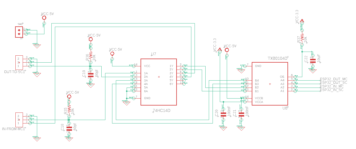
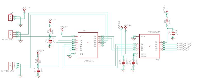
Schaltplan mit Logikgatter und Pegelwandler
, 74HC14D, VCC, 1Y, 2Y, 3Y, 4Y, 5Y, 6Y, GND, 1A, 2A, 3A, 4A, 5A, 6A, VCC-3.3, R37, 10k, C22, 10uF, TXB0104D, OE, GND, B4, B3, B2, B1, VCCB, VCCA, U8, A1, A2, A3, A4, ESP32_OUT_MC, ESP32_OUT_SC, ESP32_IN_MC, ESP32_IN_SC, C20, 100nF, C21, 100nF, IN-FROM-MC1, R35, 10k, C18, 60pF
in „Schmitt-Trigger 74HC14 mit Level Shifter“ · Mikrocontroller und Digitale Elektronik · · Schaltpläne
-
PDF
FA_SIM800L_sch.pdf
PCMSYNC 10 B4 A4 5 PCMOUT C6 9 6 SDA PCMCLK 8 NC NC 7*2 0.22uF VEXT OE GND SCL SPK1P MSQA6V1W5T2G TXB0104 GND UART_DRT SPK1N UART_RI SPL2P UART_DCD SPK2N CTS MIC1P GND GND GND GND RTS MIC1N SIM_TXD TXD MIC2P SIM_RXD RXD MIC2N 1 2 3 4 5 6 7 8 9 1 1 1 1 1 1 1 1 1 1 2 2 2 2 2 2 2 2 2 2 D D D D D D D D
in „IoT mit ATMEGA und SIM800L, Bienen Beute,“ · Mikrocontroller und Digitale Elektronik ·
-
PDF
FA_SIM800L_sch.pdf
10 B3 A3 5 STATUS PCMSYNC C6 B4 A4 PCMOUT 9 NC NC 6 SDA PCMCLK VEXT 8 OE GND 7*2 SCL 0.22uF SPK1P TXB0104 GND UART_DRT SPK1N MSQA6V1W5T2G UART_RI SPL2P UART_DCD SPK2N CTS MIC1P GND GND GND GND RTS MIC1N SIM_TXD TXD MIC2P SIM_RXD RXD MIC2N 0 2 3 4 5 6 7 8 9 0 1 2 3 4 5 6 7 8 9 D D D D D D D D D D D D
in „IoT mit ATMEGA und SIM800L, Bienen Beute,“ · Mikrocontroller und Digitale Elektronik ·
-
PDF
txs0104_Interfacing_SD_Article.pdf
between the processor and memory card. Figure 5. Auto direction-sensing voltage translator. Figure 6. TXB0108 used to interface a low-voltage processor with a SD/SDIO card. Figure 4. 52 MHz clock signal and 52 Mb/s data signals being translated from 1.8 to 3 V using a fully buffered solution. level-translation
in „TXS0104E LevelShifter“ · Mikrocontroller und Digitale Elektronik ·
-
PDF
at90can-v1.1.pdf
+ SPI 10 5 MISO 8 A 1 k 11 4 5 A R 1 MOSI D C 2 12 3 6 V Q BUTTON SCK C C117 13 2 1 SS 3 S D 100n TXB0104PWR 7 W N IC12-1 HOLD G U 4 B 2 1 3 3 5 JP9 + + GND Y B 4 L GND B 1 N1 P C115 G U C116 A D B 2 100nC C C 100n V7 V I GND D9 RN1-1 C LED0 C 330 D8 RN1-2 LED1 330 D7 RN1-3 LED2 330 D6 RN1-4 LED LED3
-
PDF
STC15F100-en.pdf
== 0) { TXB = 1; TING = 0; //stop send TEND = 1; //set send completed flag } else { TXB = CY; //write CY to TX port } } } } } //----------------------------------------- //initial UART module variable void UART_INIT
in „STC15F104W will nicht so recht“ · Mikrocontroller und Digitale Elektronik ·
-
PDF
Magazin_Bauteile.pdf
Printbuchse 2,54mm einreihig Fischer Elektronik Farnell 162-9139 10,660 10,66 4 4 5 4 Spannungspegelumsetzer TXB0104 SMD Texas Instruments Farnell 312-0964 1,710 6,84 4 5 1 1 4 Quarz SMD ABM3-14.7456MHZ-D2Y-T 14,7456 MHz, 20ppm 18pF ABRACON Farnell 246-7790 0,489 1,96 2 Quarz HC49-4H/30/50/-40+85/18PF/ATF 14,7456
-
PDF
txs0108e.pdf
device is appropriate for applications where a push-pull driver is connected to the data I/Os, but the TXB0104 device, (SCES650) 4-Bit Bidirectional Voltage-Level Translator might be a better option for such push-pull applications. The device is a semi-buffered auto-direction-sensing voltage translator design
in „Joy-IT 1,8" TFT Display: SD-Karten-Slot am Arduino“ · Mikrocontroller und Digitale Elektronik ·
-
PDF
Datenblatt_Pegelwandler_TXS0108E.pdf
device is appropriate for applications where a push-pull driver is connected to the data I/Os, but the TXB0104 device, (SCES650) 4-Bit Bidirectional Voltage-Level Translator might be a better option for such push-pull applications. The device is a semi-buffered auto-direction-sensing voltage translator design
in „Wozu Pull-Down Widerstand?“ · Mikrocontroller und Digitale Elektronik ·
-
PDF
Users-Manual-revised-4514377.pdf
your application serial port is 3.3V, you need to add level converter. It is recommended that you use TXB0104PWR from TI Company. Reference design is shown as follows: Figure 17 Reference circuit of level conversion chip 3.12 PCM and I2C Interface SLM750 provides one PCM interface which supports the following
in „USB Input/Output Error mit Kondensator beheben“ · Analoge Elektronik und Schaltungstechnik ·
-
PDF
MC9S12DG128.pdf
RX_BF / RXCAN1 / RXCAN0 / MISO0 — Port M I/O Pin 2. . . . . . . . . . . . 70 2.3.39 PM1 / TXCAN0 / TXB — Port M I/O Pin 1 . . . . . . . . . . . . . . . . . . . . . . . . . . . . . . 70 2.3.40 PM0 / RXCAN0 / RXB — Port M I/O Pin 0. . . . . . . . . . . . . . . . . . . . . . . . . . . . . . 70 2.3.41 PP7
in „HCS12 CPU Disassembler“ · Mikrocontroller und Digitale Elektronik ·
-
PDF
DSPIC33EP512GM710_datasheet.pdf
CONTINUED) bit 1 SPITBF: SPIx Transmit Buffer Full Status bit 1 = Transmit has not yet started, SPIxTXB is full 0 = Transmit has started, SPIxTXB is empty Standard Buffer Mode: Automatically set in hardware when the core writes to the SPIxBUF location, loading SPIxTXB. Automatically cleared in hardware when the SPIx module transfers data from SPIxTXB to SPIxSR. Enhanced Buffer Mode: Automatically set in hardware when the CPU writes to the SPIxBUF location, loading the last available buffer location. Automatically cleared in hardware when a buffer
in „Probleme mit SRAM 23LCV1024“ · Mikrocontroller und Digitale Elektronik ·
-
PDF
MC9S12XF512.pdf
STB2 STB3 Figure 10-1. FLEXRAY Block Diagram The protocol engine has two transmitter units TxA and TxB and two receiver units RxA and RxB for sending and receiving frames through the two FlexRay channels. The time control unit (TCU) is responsible for maintaining global clock synchronization to the FlexRay
in „Wie oft kann ein µC programmiert werden?“ · Mikrocontroller und Digitale Elektronik ·
-
PDF
MC9S12XF512.pdf
STB2 STB3 Figure 10-1. FLEXRAY Block Diagram The protocol engine has two transmitter units TxA and TxB and two receiver units RxA and RxB for sending and receiving frames through the two FlexRay channels. The time control unit (TCU) is responsible for maintaining global clock synchronization to the FlexRay
in „Probleme beim Ansteuern eines EEPROM über SPI“ · Mikrocontroller und Digitale Elektronik ·