possible.(Hi Active). • Single power supply drive is possible through the use of a built-in upper-side power-supply bootstrap circuit (Needs external capacitors). • Built-in simultaneous upper/lower ON prevention circuit to prevent arm shorting through simultaneous ON input for the upper and lower side
Signaldekodierung. Nur Textlogs mitlesen, mehrere Sichten gleichzeitig. Technik: Python >= 3.10, PySide6, python-can, pyserial. MIT-Lizenz. Entwickelt und getestet unter Windows. Linux sollte über pyserial/SocketCAN laufen, ist aber ungetestet. **Quellcode und Installation** Das Paket liegt auf
Phasen-Inverter-Hybrid-IC (IPM). Es bündelt die komplette 3-Phasen-Brücke (6 IGBTs samt Freilaufdioden), die High-Side- und Low-Side-Gate-Treiber sowie eine integrierte Überstrom- (ITRIP) und Unterspannungsschutzschaltung in einem monolithischen ZIP- Gehäuse. Ovaga Technologies +2 Dass es dieses Bauteil erwischt hat
nachgestellte PWM startet sauber und läuft auch durch. Nur ab- und zu entsteht entweder auf der High-Side oder der Low-Side ein längerer Puls, der sich natürlich negativ auf das Ausgangssignal auswirkt. Anbei ein Bild was ich meine: - gelb: low side - türkis: high side - lila: (gefiltertes) Ausgangssignal
leerlaufen kann. Sorry, ist mein erster Versuch mit Fifo und PIO. Der PIO-Code [pre] ; GPIO2 = Low-Side, GPIO3 = High-Side ; Systemtakt: 150 MHz .wrap_target ; --- HIGH-SIDE Phase --- pull block ; High-Side-Dauer aus FIFO holen mov x, osr ; Verschiebe in das X-Register
area of each pixel, the sensor achieves higher light-collection efficiency than conventional front-side illuminated (FSI) architectures. This results in quantum efficiency (QE) of up to 73% at 550 nm and 15% at 940 nm, improving performance in challenging lighting conditions and near-infrared applications
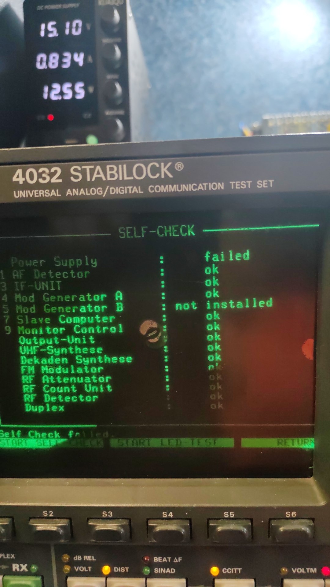
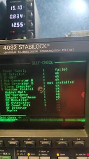
15.10 0.834 12.55 4032 STABILOCK UNIVERSAL ANALOG/DIGITAL COMMUNICATION TEST SET SELF-CHECK Power Supply failed 1 AF Detector ok 3 IF-UNIT ok 4 Mod Generator A ok 5 Mod Generator B not installed 9 Slave Computer ok Monitor Control ok Output-Unit ok UHF-Synthese ok Dekaden Synthese ok FM Modulator ok RF Attenuator ok RF Count Unit ok RF Detector ok Duplex ok Self Check failed. START SELF CHECK START LED-TEST RETURN S2 S3 S4 S5 S6 DUPLEX RX VOLT DIST SINAD CCITT VOLTM
!SB-Technik. Eine Einführung ISBN 3-7723-0462-1 in die moderne Einseitenband- und 50 lndependent-Side-Band-Technik. Von Oberingenieur Horst Pelka. - 1. Auf Praktischer Antennenbau. Eine Ober lage. Vierfachband. DM 12.80. sicht über die vielfältigen Antennenfor ISBN 3-7723-0381-1 men und ein Wegweiser
Empfangspraxis. Von moderne Einseitenband- und lndependent Siegtried W. Best.-Dreifachband.DM 9.80. Side-Band-Technik. Von Horst Pelka. - 2.,neu ISBN 3-7723-0321-8 bearbeitete Auflage. Dreifachband.M 9.80. ISBN 3-7723-0382-X Kurzwellenhörer jeden Alters finden hier Rat und Hilfe. Das gilt für alle empfangstechnischen
Hilfe eines moderne Einseitenband- und tndependent selbstgebauten Funktionstabellengebers und ei Side-Band-Technik. Von Horst Pelka.- 2.,neu nes Oszillografen logische Verknüpfungen ermit bearbeitete Auflage. Dreifachband. DM 1.80. teln, erfassen und auswerten. Von Dipi.-Phys. ISBN 3-7723-0382-X Johannes
7723-0342-0 SSB- und !SB-Technik. Eine Einführung in die moderne Einseitenband- und lndependent 38 Side-Band-Technik. Von Horst Pelka. - 2., neu bearbeitete Auflage. DM 10.80. ISBN 3-7723-0382-X Fachwörter der Elektronik. Heiße Definitionen neuester Elektronik-Begriffe. Von lng. Georg 40 Franz. - 3.,
deliver maximum charge current under all conditions require that the exposed metal pad on the back side of the ME4056 package be soldered to the PC board ground. Failure to make the thermal contact between the exposed pad on the backside of the package and the copper board will result in larger thermal
the "share user folder" in tracking the files. ... The files are not being written to either side(windows or WSA). This seems to be an internal bug with the implementation of "share user folder". The issue, though, is persistent in that it will continue to report incorrect info. ... Again,
den man die ganzen Schutzbausteine herum selbst entwickelt, oder ob man nicht mit einem Smart High-Side-Switch besser bedient ist der das alles schon integriert. Z.B. sowas hier: https://www.infineon.com/part/BTS50015-1TAD https://www.lcsc.com/product-detail/C2150052.html
→ dieser Impuls setzt gleichzeitig das bistabile Relais und den CD4017 zurück. Warum PNP als High-Side-Schalter: Da beide Minuspole des Relais dauerhaft an Masse liegen, kann die Ansteuerung nicht low-side (über GND) erfolgen. Der Treiber muss stattdessen den Pluspol der jeweiligen Spule pulsförmig auf
6∞ 0∞ 6∞ D BOTTOM VIEW S 0.0207 BSC 0.5250 BSC A TOP VIEW M / 4 A2 A1 A 7 c α 9 e b L FRONT VIEW SIDE VIEW X A PROPRIETARY INFORMATION TITLE: M PACKAGE OUTLINE, 8L uMAX/uSOP APPROVAL DOCUMENT CONTROL NO.REV. 1 – 21-0036 J 1 1 7 P 9 N INCHES MILLIMETERS I X DIM MIN MAX MIN MAX S A 0.053 0.069 1.35 1.75
JW1501A/B Multi-Mode Primary-Side Regulation (PSR) Parameters Subject to Change Without Notice DESCRIPTION FEATURES JW1501A/B is a high performance Primary Side ● Integrated with 650V MOSFET Regulation (PSR) power switch with high ●
OB2502x High Precision CC/CV Primary-Side Power Switch GENERAL DESCRIPTION FEATURES OB2502x is a high performance offline PSR power Primary-side sensing and regulation without switch for low power AC/DC charger and adapter TL431 and opto-coupler
Remark For the external views, refer to the package drawings. 6 5 4 *1. Connect the heatsink of back side at shadowed area to the board, and set electric potential open or VDD. However, do not use it as the function of electrode. Figure 3 Seiko Instruments Inc. 5 BATTERY PROTECTION IC FOR 2-SERIAL-CELL
Reference Voltage Precision: (Ta=25°C) 0.8V±1.5% (Ta=-40°C to +105°C) ±2.0% BD9615MUV-LB is a low side MOSFET controller with Frequency Range: 100kHz to 2500kHz high withstand voltage (60V). It is suitable for circuits Operating Temperature Range: -40°C to +105°C requiring low side FET such as boost
measured about at half of the inductance range. The electrical diagram has to be viewed by the pin side, it is also available the number of turns. The picture shows the complete coil and all its parts, the picture is nearly in 1:1 scale and it shows quite the real size of the coil. Coils with a parallel
und S+–F−, 4× PT POLARITY Sense tauschen oder Betrag 2× LOW auf F+–F− und S+–S−, 4× PT FORCE_SAME_SIDE Mux: Strom F+→S+, Sense F−/S− 3× OPEN, gemeinsamer Knoten Tx OPEN_Tx Ader Tx, kein Messen I ≈ 0 auf F+–F−, S+–S− bleibt PT OPEN_FORCE Stromader, 3-Leiter-Fallback prüfen I ok, alle Paare mit Sx = OPEN
the Graphic Home (GH) address will be displayed as the first 6 or 8 bits on the top row, left hand side of the LCD screen, depending on the font size selected. When using the Attribute function the GH address indicates the starting address for the Attribute RAM area. 8.2.4 Graphic Area Set (GA) Description
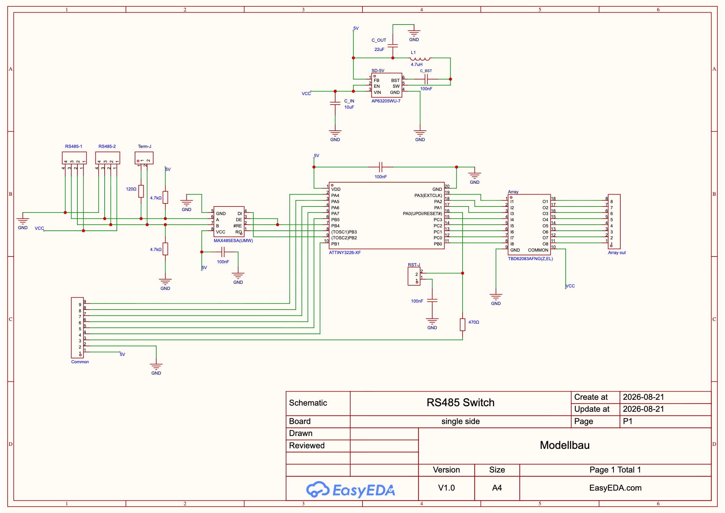
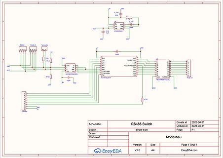
COMMON GND VCC TBD62083AFNG(Z,EL) RS485 Switch Create at 2026-08-21 Update at 2026-08-21 Board single side Page P1 Drawn Modellbau Version V1.0 Size A4 Page 1 Total 1 EasyEDA.com
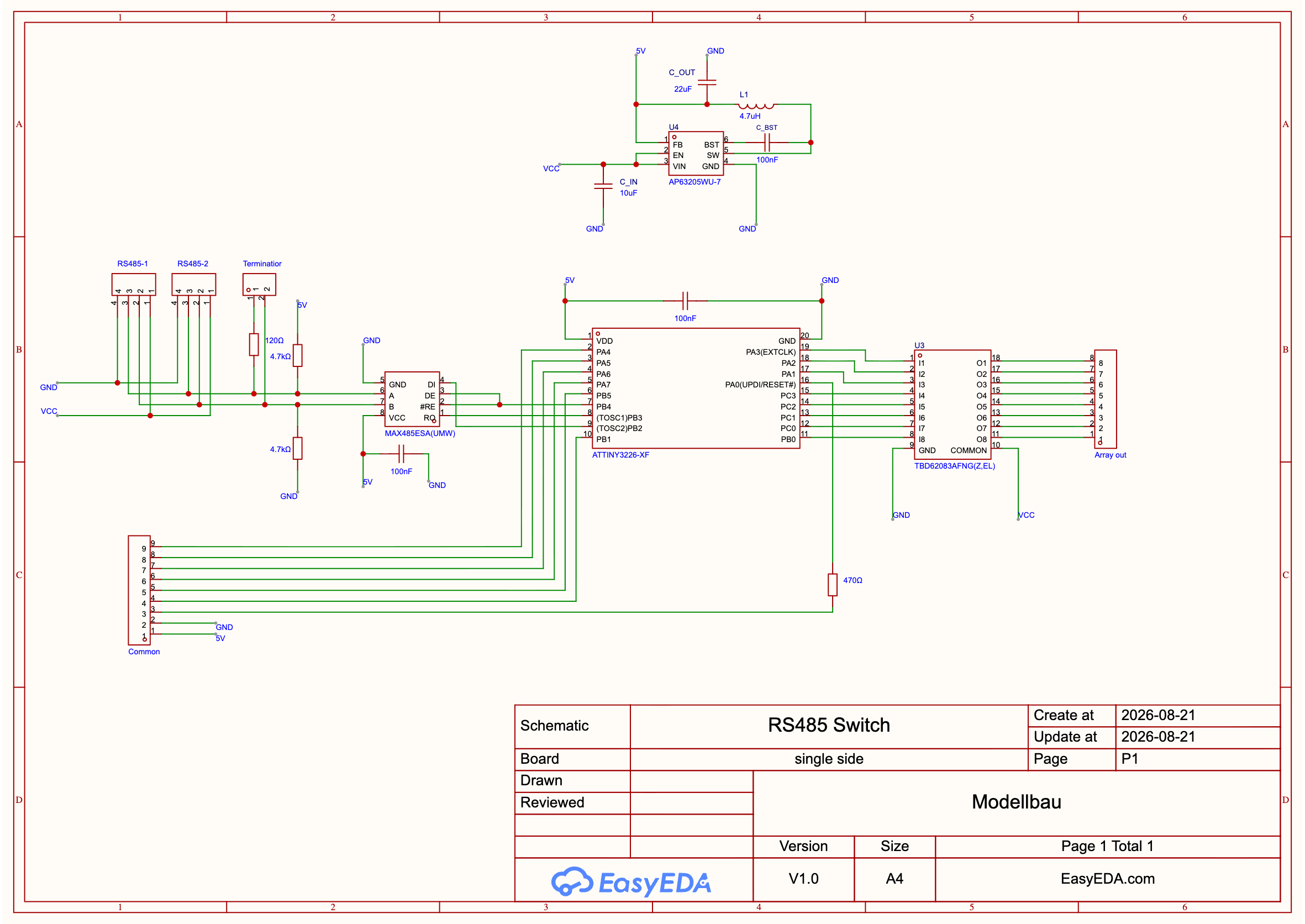
Array out COMMON VCC Schematic RS485 Switch Create at 2026-08-21 Update at 2026-08-21 Board single side Page P1 Drawn Modellbau Page 1 Total 1 Version V1.0 Size A4 EasyEDA.com
für die Dauer des Firmware Updates zum schweigen bringen. Erste Idee: der GPS Sender wird low side mit einem ULN2003A abgeschaltet. Vcc bleibt drann. => kann das funktionieren? oder können da Pegel auftreten, welche der NEO-6M nicht so mag und ich einen Hardwareschaden riskiere? Zur Sicherheit noch
Wemos gesteuert wird und den Verstärker + Boost-Wandler freischaltet. - Oder ein einzelner High-Side-Switch, der die komplette Last (5 V + Verstärker) steuert. Was wäre hier die sauberste und energieeffizienteste Lösung? Ich freue mich über Tipps zu: - geeigneten Verstärkern (klein, effizient
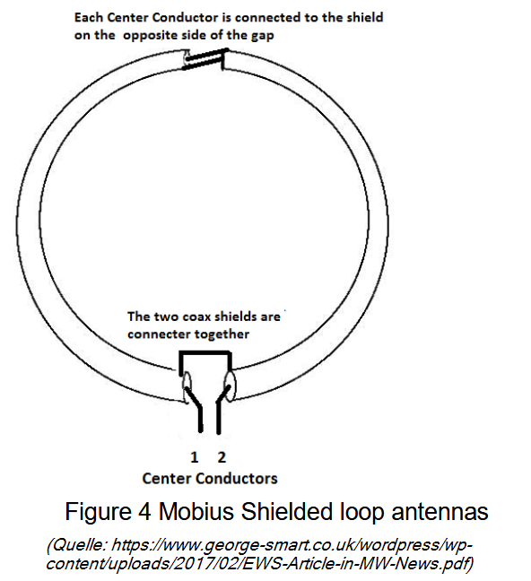
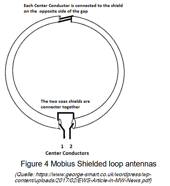
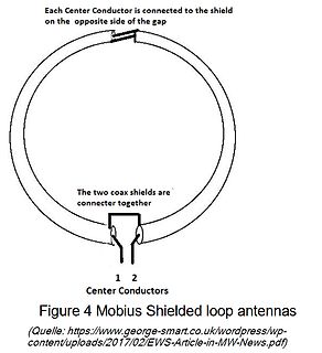
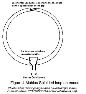
Each Center Conductor is connected to the shield on the opposite side of the gap
The two coax shields are connecter together
1 2
Center Conductors
Figure 4 Mobius Shielded loop antennas
(Quelle: https://www.george-smart.co.uk/wordpress/wp-content/uploads/2017/02/EWS-Article-in-MW-News.pdf
Hausinternetanschlüsse noch nicht so verbreitet waren. Sidux war Rolling Release, basierend auf Sid. Die ausdrücklich vorgesehene Betriebsweise war, regelmäßig Updates zu fahren, weil in Sid nunmal regelmäßig Neuerungen und Änderungen einflossen, die weitestgehend direkt weitergegeben wurden. Entsprechend
Jack V. schrieb im Beitrag #8092928: > Sidux war Rolling Release, basierend auf Sid. Die ausdrücklich > vorgesehene Betriebsweise war, regelmäßig Updates zu fahren, weil in Sid > nunmal regelmäßig Neuerungen und Änderungen einflossen, die > weitestgehend direkt weitergegeben
Heat-Sink ist. Beim Low-Side MOSFET ist daher die Heat-Sink die Switch-Node, also der Teil, der sehr schnell hohe Spannungen schaltet. In allen Design-Regeln steht, dass diese Switch-Node möglichst klein gehalten werden soll. Gleichzeitig
hat Infineon auch erkannt und deswegen das Source-Down-Package entwickelt. Du kannst für den High-Side-Schalter einen Drain-Down verwenden und für den Low-Side einen Source-Down, damit wird das Problem elegant umgangen. Dafür käme beispielsweise der hier infrage https://www.infineon.com/part/IQE030N06NM5
connector uses a standard IEEE-488 pinout. Back view 2 3 (2) Status LED (3) Firmware update button Side view 4 (4) USB-Type C connector – plug it with either a USB Type C to USB type A or USB type C to type C cable into your PC. Page | 5 LED The LED has multiple purposes as summarized in the table below
gibt unterschiedlichste Varianten mit und ohne Gewinde. ### Infineon BTS80009-SWPF-1ES – High Side-Switch für bis zu 34.5A Wer einen intelligenten High Side-Switch sucht, wird bei Infineon mit einer neuen SKU bedient. Hervorzuheben ist die weitgehende Einstellbarkeit, die die Absicherung der geschalteten
–13 Mounting the Raised Display Unit on the Short Side of the Scale First, decide whether you want to mount the display on the short side or on the back (long side) of the scale. ! Please follow the instructions given on page1–12 before you begin to change
Each Center Conductor is connected to the shield on the opposite side of the gap
The two coax shields are connecter together
1 2
Center Conductors
Figure 4 Mobius Shielded loop antennas
(Quelle: https://www.george-smart.co.uk/wordpress/wp-content/uploads/2017/02/EWS-Article-in-MW-News.pdf
fixed conveyor side for conveyor track 2 (in example of S-27 HM) Key (1) Fixed side - conveyor track 1 (4) Fastening screw (2) Fixed side - conveyor track 2 (5) Moving the fixed side - conveyor track 2 (3) Side flange
#8077236: > 1.) Der HD2AD100T --> Müsste wohl irgend ein Gate Treiber sein, oder? > Sind ein High Side und ein Low Side Mosfet in der nähe https://www.onsemi.com/download/data-sheet/pdf/fan3100t-d.pdf
schrieb: >> 1.) Der HD2AD100T --> Müsste wohl irgend ein Gate Treiber sein, oder? >> Sind ein High Side und ein Low Side Mosfet in der nähe > > https://www.onsemi.com/download/data-sheet/pdf/fan3100t-d.pdf Treffer!
Manual, Rev. N
3.4 Drive mounting
You can mount the drive in any orientation using four screws in the side-mounting holes or four screws in the bottom-mounting holes. See Figure 5 on page 22 for drive mounting dimensions. Follow these important mounting precautions when mounting the drive:
• Allow a minimum
you what to do. 2.1 Miscellaneous voltages LocateandidentifyaMolex8poleconnectorJ1002(attheinner side of the vertical rear chassis) where an 8 pole ribbon cable coming from the MB board is connected. See photo 2.1. 2.1 All voltages are measured with respect to ground (chassis). The following voltages
C Dimensions – Millimeters Loose Insulated Rigid Leads Insulated Flexible Leads 0.5 mm FRONT VIEW SIDE VIEW FRONT VIEW SIDE VIEW FRONT VIEW SIDE VIEW L T L T L T H H H S F LL 5 0 ± 5 5 3 1 ± ± F 8 8 S T H L F Nominal Tolerance Nominal Tolerance Nominal Tolerance Nominal Tolerance Nominal Tolerance 10.0

 Bild
Bild
 Bild
Bild
 Bild
Bild

 Bild
Bild
 Bild
Bild
 Bild
Bild
 Bild
Bild
 Bild
Bild
 Bild
Bild
 Bild
Bild