1 | /*****************************************************
|
2 | This program was produced by the
|
3 | CodeWizardAVR V2.03.4 Standard
|
4 | Automatic Program Generator
|
5 | © Copyright 1998-2008 Pavel Haiduc, HP InfoTech s.r.l.
|
6 | http://www.hpinfotech.com
|
7 |
|
8 | Project : PCOA_1.2
|
9 | Version :
|
10 | Date : 16.01.2009
|
11 | Author : Sascha M
|
12 | Company :
|
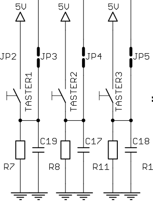
13 | Comments: Drei Schalter steuern je einen Motor.
|
14 | Sensor deaktiviert alle Motoren.
|
15 | Real-Time-Clock implementiert, auslesen durch Sensor
|
16 |
|
17 |
|
18 |
|
19 | Chip type : ATmega32
|
20 | Program type : Application
|
21 | Clock frequency : 16,000000 MHz
|
22 | Memory model : Small
|
23 | External RAM size : 0
|
24 | Data Stack size : 512
|
25 | *****************************************************/
|
26 |
|
27 | #include <mega32.h>
|
28 | #include <delay.h>
|
29 |
|
30 | // I2C Bus functions
|
31 | #asm
|
32 | .equ __i2c_port=0x15 ;PORTC
|
33 | .equ __sda_bit=1
|
34 | .equ __scl_bit=0
|
35 | #endasm
|
36 | #include <i2c.h>
|
37 |
|
38 | // DS1337 Real Time Clock functions
|
39 | #include <ds1337.h>
|
40 |
|
41 | // Standard Input/Output functions
|
42 | #include <stdio.h>
|
43 |
|
44 | // Declare your global variables here
|
45 | #define taster1 2 // PD2 an Pin 16
|
46 | #define taster2 3 // PD3 an Pin 17
|
47 | #define taster3 4 // PD4 an Pin 18
|
48 | #define motor1 5 // LED1 und Testmotor 1
|
49 | #define motor2 6 // LED2 und Testmotor 2
|
50 | #define motor3 7 // Summer und Testmotor 3
|
51 | #define sensor 5 // PC5 an Pin 27
|
52 | //#define drucke(t) printf(#t)
|
53 | void main(void)
|
54 | {
|
55 | // Declare your local variables here
|
56 | unsigned char h,m,s,da,mo,ye;
|
57 |
|
58 | // Input/Output Ports initialization
|
59 | // Port A initialization
|
60 | // Func7=In Func6=In Func5=In Func4=In Func3=In Func2=In Func1=In Func0=In
|
61 | // State7=T State6=T State5=T State4=T State3=T State2=T State1=T State0=T
|
62 | PORTA=0x00;
|
63 | DDRA=0x00;
|
64 |
|
65 | // Port B initialization
|
66 | // Func7=In Func6=In Func5=In Func4=In Func3=In Func2=In Func1=In Func0=In
|
67 | // State7=T State6=T State5=T State4=T State3=T State2=T State1=T State0=T
|
68 | PORTB=0x00;
|
69 | DDRB=0x00;
|
70 |
|
71 | // Port C initialization
|
72 | // Func7=In Func6=In Func5=In Func4=In Func3=In Func2=In Func1=In Func0=In
|
73 | // State7=T State6=T State5=T State4=T State3=T State2=T State1=T State0=T
|
74 | PORTC=0x00;
|
75 | DDRC=0x00;
|
76 |
|
77 | // Port D initialization
|
78 | // Func7=Out Func6=Out Func5=Out Func4=In Func3=In Func2=In Func1=In Func0=In
|
79 | // State7=0 State6=0 State5=0 State4=T State3=T State2=T State1=T State0=T
|
80 | PORTD=0x00;
|
81 | DDRD=0xE0;
|
82 |
|
83 | // Timer/Counter 0 initialization
|
84 | // Clock source: System Clock
|
85 | // Clock value: Timer 0 Stopped
|
86 | // Mode: Normal top=FFh
|
87 | // OC0 output: Disconnected
|
88 | TCCR0=0x00;
|
89 | TCNT0=0x00;
|
90 | OCR0=0x00;
|
91 |
|
92 | // Timer/Counter 1 initialization
|
93 | // Clock source: System Clock
|
94 | // Clock value: Timer 1 Stopped
|
95 | // Mode: Normal top=FFFFh
|
96 | // OC1A output: Discon.
|
97 | // OC1B output: Discon.
|
98 | // Noise Canceler: Off
|
99 | // Input Capture on Falling Edge
|
100 | // Timer 1 Overflow Interrupt: Off
|
101 | // Input Capture Interrupt: Off
|
102 | // Compare A Match Interrupt: Off
|
103 | // Compare B Match Interrupt: Off
|
104 | TCCR1A=0x00;
|
105 | TCCR1B=0x00;
|
106 | TCNT1H=0x00;
|
107 | TCNT1L=0x00;
|
108 | ICR1H=0x00;
|
109 | ICR1L=0x00;
|
110 | OCR1AH=0x00;
|
111 | OCR1AL=0x00;
|
112 | OCR1BH=0x00;
|
113 | OCR1BL=0x00;
|
114 |
|
115 | // Timer/Counter 2 initialization
|
116 | // Clock source: System Clock
|
117 | // Clock value: Timer 2 Stopped
|
118 | // Mode: Normal top=FFh
|
119 | // OC2 output: Disconnected
|
120 | ASSR=0x00;
|
121 | TCCR2=0x00;
|
122 | TCNT2=0x00;
|
123 | OCR2=0x00;
|
124 |
|
125 | // External Interrupt(s) initialization
|
126 | // INT0: Off
|
127 | // INT1: Off
|
128 | // INT2: Off
|
129 | MCUCR=0x00;
|
130 | MCUCSR=0x00;
|
131 |
|
132 | // Timer(s)/Counter(s) Interrupt(s) initialization
|
133 | TIMSK=0x00;
|
134 |
|
135 | // USART initialization
|
136 | // Communication Parameters: 8 Data, 1 Stop, No Parity
|
137 | // USART Receiver: On
|
138 | // USART Transmitter: On
|
139 | // USART Mode: Asynchronous
|
140 | // USART Baud Rate: 9600
|
141 | UCSRA=0x00;
|
142 | UCSRB=0x18;
|
143 | UCSRC=0x86;
|
144 | UBRRH=0x00;
|
145 | UBRRL=0x67;
|
146 |
|
147 | // Analog Comparator initialization
|
148 | // Analog Comparator: Off
|
149 | // Analog Comparator Input Capture by Timer/Counter 1: Off
|
150 | ACSR=0x80;
|
151 | SFIOR=0x00;
|
152 |
|
153 | // I2C Bus initialization
|
154 | i2c_init();
|
155 |
|
156 | rtc_set_date(16,01,9);
|
157 |
|
158 | while (1)
|
159 | {
|
160 | if (PIND &(1<<taster1)) {
|
161 | PORTD |=(1<<motor1); //LED1 und Testmotor 1 ON
|
162 | }
|
163 | if (PIND &(1<<taster2)) {
|
164 | PORTD |=(1<<motor2); //LED2 und Testmotor 2 ON
|
165 | }
|
166 | if (PIND &(1<<taster3)) {
|
167 | PORTD |=(1<<motor3); // Summer und Testmotor 3 ON
|
168 | }
|
169 | if (PINC &(1<<sensor)) {
|
170 | //delay_ms(250);
|
171 | PORTD &=~((1<<motor1)|(1<<motor2)|(1<<motor3)); // deaktiviert alle Motoren
|
172 | rtc_get_date(&da,&mo,&ye); //
|
173 | printf("\r%i.%i.200%i",da,mo,ye); // Datum lesen und an UART ausgeben
|
174 | rtc_get_time(&h,&m,&s); //
|
175 | printf("\r%i:%i:%i\n",h,m,s); // Zeit lesen und an UART ausgeben
|
176 | };
|
177 | }; // end while Arbeitsschleife
|
178 | } // end main
|