hallo leute

hatte schon vor einigen wochen ein ähnliches problem und aufeinmal ging
wieder alles aber nun da es wieder auftritt weiß ich nicht mehr weiter.

ich habe in einer bestehenden schaltung einen mega8 im einsatz, wo alles
funktioniert. da das programm nun größer wird bin ich auf den mega328
umgestiegen der auch zeitweise funktioniert. alle register habe ich
angepasst und fuse auf extern quarz geschalten.

steuere mit der schaltung ein lcd an, das mit dem mega328 plötzlich nach
einiger zeit balken anzeigt als würde es nicht richtig angesteuert.
ok beim ersten mal nahm ich einen 2. mega328 mit funktionierendem
programm und deto - balken. nach einigen hin und her funktioniert
plötzlich das lcd mit beiden mega328.

heute das selbe problem.
habe alle pins durchgemessen, verbunden ist alles.
nehm ich den mega8 funktioniert alles problemlos.
jedoch mitn mega328, kann ich reseten und neu programmen soviel ich
will, nix funkt.
kann mir das verhalten nicht erklären wieso sich der mega328 aufhängt,
habe brownout disable/2,7V
timing vom quarz leicht verändert

aja system läuft mit 3,3v und 16mhz
ich gönn dem mega328 wieder ne pause vielleicht funkt er morgen?!

hat wer nen tipp?
ich kann mir nicht vorstellen, dass am programm liegt...
Hallo,

> system läuft mit 3,3v und 16mhz

Ich denke, es sind 16 Megahertz und keine Millihertz ...

Hast du die Datenblätter studiert? Dann müsstest du feststellen, dass
bei beiden Controllern 16MHz Takt nur bei einer Versorgungsspannung von
4.5V bis 5.5V erlaubt sind. D.h., du betreibst die Controller mit den
3.3V ausserhalb der von ATMEL vorgegebenen Spezifikationen.
Das kann funktionieren, muss aber nicht; es wird von ATMEL nicht
garantiert.

Also muss entweder der Takt runter (nur beim Mega328; der Mega8 ist gar
nicht für 3.3V vorgesehen, nur der Mega8V) oder die Versorgungsspannung
auf 5V rauf.

Erst danach macht es Sinn, weiter nach Fehlern zu suchen ...
ok kann ich versuchen

MHz natürlich ;-)
irgendwo im datenblatt habe ich gefunden, so eine grafik die bei 2,7v
bei 10Mhz war und bei 5V bei 20Mhz, so steil ansteigend. zumindestens
bei der hat es so ausgesehen, dass bei 3,3v sich 16Mhz ausgehen sollten.
jedenfalls werde ich mal auf die internen osi umschalten da kann ich den
externen quarz dran hängen lassen und es sollt funktionieren. berichte
am nachmittag wieder ;-)

der mega8 läuft problemlos, habe mal in einem thread gelesen, dass die
mega8 selektiert sind. d.h. die besseren werden zu 2,7-5,5v &16Mhz
modellen die anderen zu 5V modellen mit 8mhz. jedenfalls läuft mein
mega8-16pu stabil.

mfg
Lowtzow .... schrieb:
> zumindestens
> bei der hat es so ausgesehen,

nur mit Knick in der Optik...außerdem ist den mega328-Grafiken die
3,3V-Kurve immer nur bis 12,6 MHz. Und auch wenn man nur von der
Übersichtskurve ausgeht, was hat dich denn daran gehindert, mal eben aus
zu rechnen, wie hoch die Maxfrequenz bei 3,3V ist?
tja, wie gesagt, ein bestehendes system, hab die kurve dann auch nur mal
zufällig gesehen...

hab jetzt vorher schon mal nachgerechnet und bei 3,3v gehts max bis
13Mhz.
habe die frequenz auf interne 8Mhz gestellt und habe leider das selbe
problem, wenn ich das selbe Programm (register natürlich angepasst) auf
einen Mega8 mit internen 8Mhz betreiber funktioniert alles problemlos


ich häng mal sicherheitshalber den code für den mega328 an
1 | /*****************************************************************
|
2 | Titel: Messung des Puls mittels eines Polar Brustgurt
|
3 | |
4 | Author: Alex & Michael
|
5 | |
6 | Software: AVR-GCC 4.14
|
7 | |
8 | Hardware: TL074
|
9 | LM567
|
10 | HD44780 compatible text LCD
|
11 | |
12 | *******************************************************************/
|
13 | |
14 | |
15 | #include <stdlib.h> |
16 | #include <avr/io.h> |
17 | #include "lcd.h" |
18 | #include "HRM11-mega328.h" // Author: Peter Fleury |
19 | #include <avr/signal.h> |
20 | #include <inttypes.h> |
21 | |
22 | |
23 | ISR(TIMER1_COMPA_vect){ //Interrupt routine, variable wird jede ms erhöht |
24 | run_ms1++; |
25 | |
26 | |
27 | }
|
28 | |
29 | ISR(INT0_vect){ //Ext.Interrupt auf PIN0 |
30 | |
31 | static volatile uint16_t int0_falling_time = 0; //wird für Int0 benötigt |
32 | static volatile uint16_t int0_rising_time = 0; //wird für Int0 benötigt |
33 | |
34 | |
35 | if ( !( EICRA & (1<< ISC00 )) ) { // ICS00=0 => Interrupt bei fallender Flanke |
36 | |
37 | int0_falling_time = run_ms1; //Auslösezeit wird gespeichert |
38 | |
39 | EICRA |= ( 1 << ISC00 ) | ( 1 << ISC01 ); //ICS00 & ICS01 = 1 => INT0 reagiert auf steigende Flanke |
40 | |
41 | }
|
42 | |
43 | else{ //ICS00&ICS01 =1 Interrupt bei steigender Flanke |
44 | |
45 | int0_rising_time = run_ms1; //Auslösezeit wird gespeichert |
46 | |
47 | EICRA &= ~(1 << ISC00); //ICS00 = 0 => INT0 reagiert auf fallende Flanke |
48 | |
49 | }
|
50 | |
51 | if( ( int0_rising_time - int0_falling_time ) >= signal_time_low && |
52 | ( int0_rising_time - int0_falling_time ) <= signal_time_high) { // wenn signallänge 3-7ms |
53 | |
54 | //impuls_3_start_time[run_impuls_3] = run_ms1; //bei 3-7ms impuls startzeit ins array schreiben
|
55 | impuls_3_start_time[run_impuls_3] = int0_rising_time; //bei 3-7ms impuls startzeit ins array schreiben |
56 | |
57 | run_impuls_3++; //array_laufvariable erhöhen |
58 | //**************************************************************************************
|
59 | test2=run_impuls_3; |
60 | //**************************************************************************************
|
61 | if (run_impuls_3>=array_lenght_impuls_3) { //array_laufvariable = 0 |
62 | run_impuls_3 = 0; |
63 | }
|
64 | }
|
65 | |
66 | }
|
67 | |
68 | /********************************************************************************************
|
69 | In dieser Funktion wird der Code für die Polar-Funkstrecke gesucht
|
70 | solange kein Code gefunden wurd d.h. code = 0 wird dieses Programm durchlaufen
|
71 | wenn ein Code gefunden wurde, wird dieser der variable code zugewiesen
|
72 | ********************************************************************************************/
|
73 | void code_search(void){ //code für übertragung wird gesucht |
74 | |
75 | if (code==0){ //solange kein code gefunden, wird routine durchlaufen |
76 | |
77 | static uint8_t search = 0; //varriable für codesuche |
78 | |
79 | for (uint8_t i= 0; i < array_lenght_impuls_3 ; i++){ //Array wird durchsucht |
80 | |
81 | search+=5; //suchvarriable wird jeweils um 5 erhöht |
82 | |
83 | if(search>=255) //falls suchvariable überläuft |
84 | search=0; |
85 | |
86 | if( impuls_3_start_time[i+1] - impuls_3_start_time[i] == search && |
87 | impuls_3_start_time[i+2] - impuls_3_start_time[i] == search+20){ |
88 | |
89 | |
90 | code=search; //wenn code gefunden, wird dieser hier übergeben |
91 | |
92 | }
|
93 | }
|
94 | }
|
95 | }
|
96 | |
97 | /********************************************************************************************
|
98 | Hier wird das Array nach gültigen Signalen durchsucht also unsren 3 spikes,
|
99 | wurden die 3 spikes gefunden so wird die startzeit in ein array geschriben,
|
100 | womit weiter gerechnet werden kann
|
101 | *********************************************************************************************/
|
102 | void impuls_decode(void){ |
103 | |
104 | if (code!=0){ //erst wenn code gefunden wurde, wird diese routine durchlaufen |
105 | |
106 | static uint8_t j; //laufvariable für signal start time |
107 | |
108 | for (uint8_t i = 0; i < array_lenght_impuls_3 ; i++){ //60 werte array wird durchlaufen |
109 | |
110 | if( impuls_3_start_time[i+1] - impuls_3_start_time[i] <= code+5 && |
111 | impuls_3_start_time[i+1] - impuls_3_start_time[i] >= code-5 ){ |
112 | |
113 | impuls_1_start_time[j] = impuls_3_start_time[i]; // gültige signale in impuls_start_time array schreiben |
114 | |
115 | //test5=j;
|
116 | j++; |
117 | |
118 | test3=j; |
119 | |
120 | if(j>array_lenght_impuls_1){ |
121 | j=0; |
122 | }
|
123 | }
|
124 | }
|
125 | }
|
126 | }
|
127 | |
128 | |
129 | |
130 | |
131 | void puls_berechnung(void){ |
132 | |
133 | if(run_sek>=run_sek3) { // >= für LCD aktualisierung ca 100ms |
134 | |
135 | run_sek3=run_sek + 1; |
136 | if(run_sek3>=62){ |
137 | run_sek3=0; |
138 | |
139 | // test7=run_sek3;
|
140 | }
|
141 | |
142 | static uint8_t k = 0; |
143 | if(code != 0) { |
144 | for(uint8_t j = 0; j < array_lenght_impuls_1 ; j++){ //60 werte |
145 | |
146 | if (impuls_1_start_time[j+1]-impuls_1_start_time[j] >= 300 && |
147 | impuls_1_start_time[j+1]-impuls_1_start_time[j] <= 1200) { //ob puls zwischen 60-200schläge pro minute 1sek-0,3sek |
148 | |
149 | heartbeat_now = 60000 / ( (float) impuls_1_start_time[j+1]-(float)impuls_1_start_time[j] ); //aus der laufzeit wird der puls berechnet |
150 | |
151 | heartbeat[k]=heartbeat_now; //gültigen puls in heartbeat array schreiben |
152 | |
153 | |
154 | |
155 | /*****************************************************************
|
156 | min und max werte im bezug auf den durchschnittpuls herausfiltern
|
157 | |
158 | puls>>durchschnitt => puls = durchschnitt
|
159 | puls<<durchschnitt => puls = durchschnitt
|
160 | *****************************************************************/
|
161 | uint32_t avarange=0; //hilfsvariable für duchschnitt |
162 | |
163 | for (uint8_t m=0;m<=array_lenght_heartbeat_start-1;m++){ |
164 | avarange += heartbeat[k]; //alle werte aufsumieren |
165 | }
|
166 | avarange/=array_lenght_heartbeat_start; //durchschnitt berechnen |
167 | |
168 | for (uint8_t m=0;m<=array_lenght_heartbeat_start-1;m++){ |
169 | |
170 | if(avarange+20>heartbeat[m]) //puls>>durchschnitt => puls = durchschnitt |
171 | heartbeat[m]=avarange; |
172 | |
173 | if(avarange-20<heartbeat[m]) //puls<<durchschnitt => puls = durchschnitt |
174 | heartbeat[m]=avarange; |
175 | }
|
176 | |
177 | k++; |
178 | ////////////////////////////////////////////////
|
179 | test5=k; |
180 | ////////////////////////////////////////////////
|
181 | |
182 | if(k>=array_lenght_heartbeat_start) |
183 | k=0; |
184 | |
185 | }
|
186 | }
|
187 | }
|
188 | |
189 | |
190 | |
191 | }
|
192 | |
193 | }
|
194 | |
195 | |
196 | |
197 | |
198 | |
199 | |
200 | |
201 | |
202 | |
203 | |
204 | |
205 | int main(void){ |
206 | |
207 | |
208 | PORTD |= (1<<PORTD2); //PUll-up PD2 einschalten |
209 | DDRD &= ~(1 << DDD2); //PD2 => Eingang |
210 | |
211 | |
212 | //************* Timer1 config für 1ms
|
213 | TIMSK1 |= (1<<OCIE1A); //Timer1 Output Compare A MAtch Interrupt Enable |
214 | OCR1A = 1000; // von 0 bis zu disem Wert wird gezählt 16Mhz/(2*8*(1/1ms)) |
215 | TCCR1B |= (1<<CS11) | (1<<WGM12); //F_CPU/8 & CTC Mode |
216 | sei(); //Globale Interrupt enable |
217 | //***********************************
|
218 | |
219 | //*************Ext.Interrupt0 config Signalerkennung
|
220 | EIMSK|=(1<<INT0); //Ext. Interrupt aktivieren PD2 |
221 | EICRA|=(1<<ISC00); //Any logical change on INT0 generates an interrupt request. |
222 | //************************************
|
223 | |
224 | lcd_init(LCD_DISP_ON); //Display initialisieren |
225 | |
226 | |
227 | |
228 | for(;;){ |
229 | lcd_gotoxy(0,0); //zu anfangskoordinaten des lcd springen |
230 | |
231 | impuls_decode(); |
232 | |
233 | puls_berechnung(); |
234 | // wenn noch kein code vorhanden -> codesuche
|
235 | code_search(); |
236 | |
237 | |
238 | |
239 | run_sek=run_ms1/1000; //millisikunden in sekunden umrechnen und varaible zuordnen |
240 | if (run_sek >= 62){ //wenn sekunden 62 ->0 |
241 | run_sek=0; |
242 | run_sek2=0; |
243 | }
|
244 | if (run_ms1 >=62050) |
245 | run_ms1=0; |
246 | |
247 | |
248 | |
249 | |
250 | if(run_sek>=run_sek2) { // >= für LCD aktualisierung ca 100ms |
251 | run_sek2++; // um 100ms erhöht |
252 | |
253 | |
254 | /****************************************************
|
255 | gleitender mittelwert aktualisierungsadauer 8sek
|
256 | |
257 | output = input/8 + output - output/8
|
258 | ****************************************************/
|
259 | heartbeat_input=heartbeat_now; |
260 | heartbeat_output=heartbeat_input/8+heartbeat_output-(heartbeat_output/8); //averaging data stream |
261 | |
262 | |
263 | lcd_clrscr(); //lcd wird gelöscht |
264 | |
265 | char text[177]; //wird für die übergabe für sprintf benötigt |
266 | //ZEILE 1//
|
267 | lcd_gotoxy(0,0); |
268 | sprintf(text,"code:%d sek%u",code, run_sek);; //ausgabe adc0 und akt.intervall via sprintf |
269 | //sprintf(text,"%u %u %u %u %u",heartbeat[0],heartbeat[1],heartbeat[2],heartbeat[3],heartbeat[4]);
|
270 | lcd_puts(text); //text aus sprintf wird auf dem lcd ausgegeben |
271 | |
272 | |
273 | lcd_gotoxy(0,1); |
274 | //ZEILE 3//
|
275 | //sprintf(text,"3im%u 1im%u bpm%u",test2, test3,test5);; //ausgabe adc0 und akt.intervall via sprintf
|
276 | sprintf(text,"%u %u %u %u %u",impuls_3_start_time[5],impuls_3_start_time[6],impuls_3_start_time[7],impuls_3_start_time[8],impuls_3_start_time[9]); |
277 | lcd_puts(text); |
278 | |
279 | lcd_gotoxy(0,2); |
280 | //ZEILE 3//
|
281 | sprintf(text,"average bpm %u ",(int)heartbeat_now);; //ausgabe adc0 und akt.intervall via sprintf |
282 | lcd_puts(text); |
283 | |
284 | |
285 | lcd_gotoxy(0,3); |
286 | //ZEILE 3//
|
287 | sprintf(text,"in%u out%u",(int)heartbeat_input,(int)heartbeat_output); //ausgabe adc0 und akt.intervall via sprintf |
288 | lcd_puts(text); |
289 | |
290 | |
291 | |
292 | |
293 | }
|
294 | }
|
295 | }
|
das h. file
1 | #define signal_time_low 3 //min. länge des Signals
|
2 | #define signal_time_high 18 //max. länge des Signals
|
3 | |
4 | #define signal_delay_low 10 //max. ldelay des Signals ca 20ms
|
5 | #define signal_delay_high 25
|
6 | #define array_lenght_impuls_3 60 //Array größe
|
7 | #define array_lenght_impuls_1 25 //Array größe
|
8 | #define array_lenght_heartbeat_start 20 //Array größe
|
9 | |
10 | |
11 | static volatile uint16_t run_ms1 = 0; //wird jede ms um 1 erhöht 0-65535ms => ca.65sek |
12 | |
13 | |
14 | uint16_t impuls_3_start_time[array_lenght_impuls_3]; //hier wird die startzeit der impulse geschrieben |
15 | uint16_t impuls_1_start_time[array_lenght_impuls_1]; //hier wird die startzeit der signale geschrieben |
16 | static volatile uint8_t run_impuls_3 = 0; //Array Laufvariable |
17 | static volatile uint8_t run_impuls_1 = 0; //Array Laufvariable |
18 | |
19 | uint8_t heartbeat[array_lenght_heartbeat_start]={0}; //array für 10 Werte |
20 | uint8_t heartbeat_ave[array_lenght_heartbeat_start]; |
21 | |
22 | |
23 | uint32_t mittelwert_alt=0; |
24 | uint32_t mittelwert_neu=0; |
25 | uint32_t heartbeat_output=90; |
26 | uint32_t heartbeat_input=0; |
27 | uint8_t heartbeat_now=0; |
28 | |
29 | |
30 | uint8_t test2 =0; |
31 | uint8_t test3=0; |
32 | //uint8_t test4=0;
|
33 | uint8_t test5=0; |
34 | |
35 | |
36 | |
37 | uint8_t run_sek=0; |
38 | uint8_t run_sek2=0; |
39 | uint8_t run_sek3=0; |
40 | |
41 | |
42 | |
43 | uint8_t code = 0; |
44 | |
45 | extern void ISR(TIMER1_COMPA_vect); |
46 | extern void ISR(INT0_vect); |
47 | extern void code_search(void); |
48 | extern void impuls_decode(void); |
49 | extern void puls_berechnung(void); |
50 | extern int main(void); |
und die lcd.h
1 | #ifndef LCD_H
|
2 | #define LCD_H
|
3 | /*************************************************************************
|
4 | Title : C include file for the HD44780U LCD library (lcd.c)
|
5 | Author: Peter Fleury <pfleury@gmx.ch> http://jump.to/fleury
|
6 | File: $Id: lcd.h,v 1.13.2.2 2006/01/30 19:51:33 peter Exp $
|
7 | Software: AVR-GCC 3.3
|
8 | Hardware: any AVR device, memory mapped mode only for AT90S4414/8515/Mega
|
9 | ***************************************************************************/
|
10 | |
11 | /**
|
12 | @defgroup pfleury_lcd LCD library
|
13 | @code #include <lcd.h> @endcode
|
14 |
|
15 | @brief Basic routines for interfacing a HD44780U-based text LCD display
|
16 | |
17 | Originally based on Volker Oth's LCD library,
|
18 | changed lcd_init(), added additional constants for lcd_command(),
|
19 | added 4-bit I/O mode, improved and optimized code.
|
20 |
|
21 | Library can be operated in memory mapped mode (LCD_IO_MODE=0) or in
|
22 | 4-bit IO port mode (LCD_IO_MODE=1). 8-bit IO port mode not supported.
|
23 | |
24 | Memory mapped mode compatible with Kanda STK200, but supports also
|
25 | generation of R/W signal through A8 address line.
|
26 |
|
27 | @author Peter Fleury pfleury@gmx.ch http://jump.to/fleury
|
28 | |
29 | on my home page.
|
30 | |
31 | */
|
32 | |
33 | /*@{*/
|
34 | |
35 | #if (__GNUC__ * 100 + __GNUC_MINOR__) < 303
|
36 | #error "This library requires AVR-GCC 3.3 or later, update to newer AVR-GCC compiler !"
|
37 | #endif
|
38 | |
39 | #include <inttypes.h> |
40 | #include <avr/pgmspace.h> |
41 | |
42 | /**
|
43 | * @name Definitions for MCU Clock Frequency
|
44 | * Adapt the MCU clock frequency in Hz to your target.
|
45 | */
|
46 | #define XTAL 8000000 /**< clock frequency in Hz, used to calculate delay timer */ |
47 | |
48 | |
49 | /**
|
50 | * @name Definition for LCD controller type
|
51 | * Use 0 for HD44780 controller, change to 1 for displays with KS0073 controller.
|
52 | */
|
53 | #define LCD_CONTROLLER_KS0073 0 /**< Use 0 for HD44780 controller, 1 for KS0073 controller */ |
54 | |
55 | /**
|
56 | * @name Definitions for Display Size
|
57 | * Change these definitions to adapt setting to your display
|
58 | */
|
59 | #define LCD_LINES 4 /**< number of visible lines of the display */ |
60 | #define LCD_DISP_LENGTH 16 /**< visibles characters per line of the display */ |
61 | #define LCD_LINE_LENGTH 0x40 /**< internal line length of the display */ |
62 | #define LCD_START_LINE1 0x00 /**< DDRAM address of first char of line 1 */ |
63 | #define LCD_START_LINE2 0x40 /**< DDRAM address of first char of line 2 */ |
64 | #define LCD_START_LINE3 0x10 /**< DDRAM address of first char of line 3 */ |
65 | #define LCD_START_LINE4 0x50 /**< DDRAM address of first char of line 4 */ |
66 | #define LCD_WRAP_LINES 0 /**< 0: no wrap, 1: wrap at end of visibile line */ |
67 | |
68 | |
69 | #define LCD_IO_MODE 1 /**< 0: memory mapped mode, 1: IO port mode */ |
70 | #if LCD_IO_MODE
|
71 | /**
|
72 | * @name Definitions for 4-bit IO mode
|
73 | * Change LCD_PORT if you want to use a different port for the LCD pins.
|
74 | *
|
75 | * The four LCD data lines and the three control lines RS, RW, E can be on the
|
76 | * same port or on different ports.
|
77 | * Change LCD_RS_PORT, LCD_RW_PORT, LCD_E_PORT if you want the control lines on
|
78 | * different ports.
|
79 | *
|
80 | * Normally the four data lines should be mapped to bit 0..3 on one port, but it
|
81 | * is possible to connect these data lines in different order or even on different
|
82 | * ports by adapting the LCD_DATAx_PORT and LCD_DATAx_PIN definitions.
|
83 | *
|
84 | */
|
85 | #define LCD_PORT PORTC /**< port for the LCD lines */ |
86 | #define LCD_DATA0_PORT PORTD /**< port for 4bit data bit 0 */ |
87 | #define LCD_DATA1_PORT PORTD /**< port for 4bit data bit 1 */ |
88 | #define LCD_DATA2_PORT PORTB /**< port for 4bit data bit 2 */ |
89 | #define LCD_DATA3_PORT PORTB /**< port for 4bit data bit 3 */ |
90 | #define LCD_DATA0_PIN 6 /**< pin for 4bit data bit 0 */ |
91 | #define LCD_DATA1_PIN 7 /**< pin for 4bit data bit 1 */ |
92 | #define LCD_DATA2_PIN 0 /**< pin for 4bit data bit 2 */ |
93 | #define LCD_DATA3_PIN 1 /**< pin for 4bit data bit 3 */ |
94 | #define LCD_RS_PORT PORTD /**< port for RS line */ |
95 | #define LCD_RS_PIN 3 /**< pin for RS line */ |
96 | #define LCD_RW_PORT PORTD /**< port for RW line */ |
97 | #define LCD_RW_PIN 4 /**< pin for RW line */ |
98 | #define LCD_E_PORT PORTD /**< port for Enable line */ |
99 | #define LCD_E_PIN 5 /**< pin for Enable line */ |
100 | |
101 | #elif defined(__AVR_AT90S4414__) || defined(__AVR_AT90S8515__) || defined(__AVR_ATmega64__) || \
|
102 | defined(__AVR_ATmega8515__)|| defined(__AVR_ATmega103__) || defined(__AVR_ATmega128__) || \
|
103 | defined(__AVR_ATmega161__) || defined(__AVR_ATmega162__)
|
104 | /*
|
105 | * memory mapped mode is only supported when the device has an external data memory interface
|
106 | */
|
107 | #define LCD_IO_DATA 0xC000 /* A15=E=1, A14=RS=1 */ |
108 | #define LCD_IO_FUNCTION 0x8000 /* A15=E=1, A14=RS=0 */ |
109 | #define LCD_IO_READ 0x0100 /* A8 =R/W=1 (R/W: 1=Read, 0=Write */ |
110 | #else
|
111 | #error "external data memory interface not available for this device, use 4-bit IO port mode"
|
112 | |
113 | #endif
|
114 | |
115 | |
116 | /**
|
117 | * @name Definitions for LCD command instructions
|
118 | * The constants define the various LCD controller instructions which can be passed to the
|
119 | * function lcd_command(), see HD44780 data sheet for a complete description.
|
120 | */
|
121 | |
122 | /* instruction register bit positions, see HD44780U data sheet */
|
123 | #define LCD_CLR 0 /* DB0: clear display */ |
124 | #define LCD_HOME 1 /* DB1: return to home position */ |
125 | #define LCD_ENTRY_MODE 2 /* DB2: set entry mode */ |
126 | #define LCD_ENTRY_INC 1 /* DB1: 1=increment, 0=decrement */ |
127 | #define LCD_ENTRY_SHIFT 0 /* DB2: 1=display shift on */ |
128 | #define LCD_ON 3 /* DB3: turn lcd/cursor on */ |
129 | #define LCD_ON_DISPLAY 2 /* DB2: turn display on */ |
130 | #define LCD_ON_CURSOR 1 /* DB1: turn cursor on */ |
131 | #define LCD_ON_BLINK 0 /* DB0: blinking cursor ? */ |
132 | #define LCD_MOVE 4 /* DB4: move cursor/display */ |
133 | #define LCD_MOVE_DISP 3 /* DB3: move display (0-> cursor) ? */ |
134 | #define LCD_MOVE_RIGHT 2 /* DB2: move right (0-> left) ? */ |
135 | #define LCD_FUNCTION 5 /* DB5: function set */ |
136 | #define LCD_FUNCTION_8BIT 4 /* DB4: set 8BIT mode (0->4BIT mode) */ |
137 | #define LCD_FUNCTION_2LINES 3 /* DB3: two lines (0->one line) */ |
138 | #define LCD_FUNCTION_10DOTS 2 /* DB2: 5x10 font (0->5x7 font) */ |
139 | #define LCD_CGRAM 6 /* DB6: set CG RAM address */ |
140 | #define LCD_DDRAM 7 /* DB7: set DD RAM address */ |
141 | #define LCD_BUSY 7 /* DB7: LCD is busy */ |
142 | |
143 | /* set entry mode: display shift on/off, dec/inc cursor move direction */
|
144 | #define LCD_ENTRY_DEC 0x04 /* display shift off, dec cursor move dir */ |
145 | #define LCD_ENTRY_DEC_SHIFT 0x05 /* display shift on, dec cursor move dir */ |
146 | #define LCD_ENTRY_INC_ 0x06 /* display shift off, inc cursor move dir */ |
147 | #define LCD_ENTRY_INC_SHIFT 0x07 /* display shift on, inc cursor move dir */ |
148 | |
149 | /* display on/off, cursor on/off, blinking char at cursor position */
|
150 | #define LCD_DISP_OFF 0x08 /* display off */ |
151 | #define LCD_DISP_ON 0x0C /* display on, cursor off */ |
152 | #define LCD_DISP_ON_BLINK 0x0D /* display on, cursor off, blink char */ |
153 | #define LCD_DISP_ON_CURSOR 0x0E /* display on, cursor on */ |
154 | #define LCD_DISP_ON_CURSOR_BLINK 0x0F /* display on, cursor on, blink char */ |
155 | |
156 | /* move cursor/shift display */
|
157 | #define LCD_MOVE_CURSOR_LEFT 0x10 /* move cursor left (decrement) */ |
158 | #define LCD_MOVE_CURSOR_RIGHT 0x14 /* move cursor right (increment) */ |
159 | #define LCD_MOVE_DISP_LEFT 0x18 /* shift display left */ |
160 | #define LCD_MOVE_DISP_RIGHT 0x1C /* shift display right */ |
161 | |
162 | /* function set: set interface data length and number of display lines */
|
163 | #define LCD_FUNCTION_4BIT_1LINE 0x20 /* 4-bit interface, single line, 5x7 dots */ |
164 | #define LCD_FUNCTION_4BIT_2LINES 0x28 /* 4-bit interface, dual line, 5x7 dots */ |
165 | #define LCD_FUNCTION_8BIT_1LINE 0x30 /* 8-bit interface, single line, 5x7 dots */ |
166 | #define LCD_FUNCTION_8BIT_2LINES 0x38 /* 8-bit interface, dual line, 5x7 dots */ |
167 | |
168 | |
169 | #define LCD_MODE_DEFAULT ((1<<LCD_ENTRY_MODE) | (1<<LCD_ENTRY_INC) )
|
170 | |
171 | |
172 | |
173 | /**
|
174 | * @name Functions
|
175 | */
|
176 | |
177 | |
178 | /**
|
179 | @brief Initialize display and select type of cursor
|
180 | @param dispAttr \b LCD_DISP_OFF display off\n
|
181 | \b LCD_DISP_ON display on, cursor off\n
|
182 | \b LCD_DISP_ON_CURSOR display on, cursor on\n
|
183 | \b LCD_DISP_ON_CURSOR_BLINK display on, cursor on flashing
|
184 | @return none
|
185 | */
|
186 | extern void lcd_init(uint8_t dispAttr); |
187 | |
188 | |
189 | /**
|
190 | @brief Clear display and set cursor to home position
|
191 | @param void
|
192 | @return none
|
193 | */
|
194 | extern void lcd_clrscr(void); |
195 | |
196 | |
197 | /**
|
198 | @brief Set cursor to home position
|
199 | @param void
|
200 | @return none
|
201 | */
|
202 | extern void lcd_home(void); |
203 | |
204 | |
205 | /**
|
206 | @brief Set cursor to specified position
|
207 |
|
208 | @param x horizontal position\n (0: left most position)
|
209 | @param y vertical position\n (0: first line)
|
210 | @return none
|
211 | */
|
212 | extern void lcd_gotoxy(uint8_t x, uint8_t y); |
213 | |
214 | |
215 | /**
|
216 | @brief Display character at current cursor position
|
217 | @param c character to be displayed
|
218 | @return none
|
219 | */
|
220 | extern void lcd_putc(char c); |
221 | |
222 | |
223 | /**
|
224 | @brief Display string without auto linefeed
|
225 | @param s string to be displayed
|
226 | @return none
|
227 | */
|
228 | extern void lcd_puts(const char *s); |
229 | |
230 | |
231 | /**
|
232 | @brief Display string from program memory without auto linefeed
|
233 | @param s string from program memory be be displayed
|
234 | @return none
|
235 | @see lcd_puts_P
|
236 | */
|
237 | extern void lcd_puts_p(const char *progmem_s); |
238 | |
239 | |
240 | /**
|
241 | @brief Send LCD controller instruction command
|
242 | @param cmd instruction to send to LCD controller, see HD44780 data sheet
|
243 | @return none
|
244 | */
|
245 | extern void lcd_command(uint8_t cmd); |
246 | |
247 | |
248 | /**
|
249 | @brief Send data byte to LCD controller
|
250 |
|
251 | Similar to lcd_putc(), but without interpreting LF
|
252 | @param data byte to send to LCD controller, see HD44780 data sheet
|
253 | @return none
|
254 | */
|
255 | extern void lcd_data(uint8_t data); |
256 | |
257 | |
258 | /**
|
259 | @brief macros for automatically storing string constant in program memory
|
260 | */
|
261 | #define lcd_puts_P(__s) lcd_puts_p(PSTR(__s))
|
262 | |
263 | /*@}*/
|
264 | #endif //LCD_H
|
In der lcd.h ist XTAL auf 8Mhz gesetzt. Stimmt das mit FCPU überein?
Werden die delay.h Routinen benutzt?
Poste mal Deine Schaltung.
Das LCD funktioniert mit 3,3V?
Angehängte Dateien:
-

hrm_ver_1-8.sch.png
26 KB
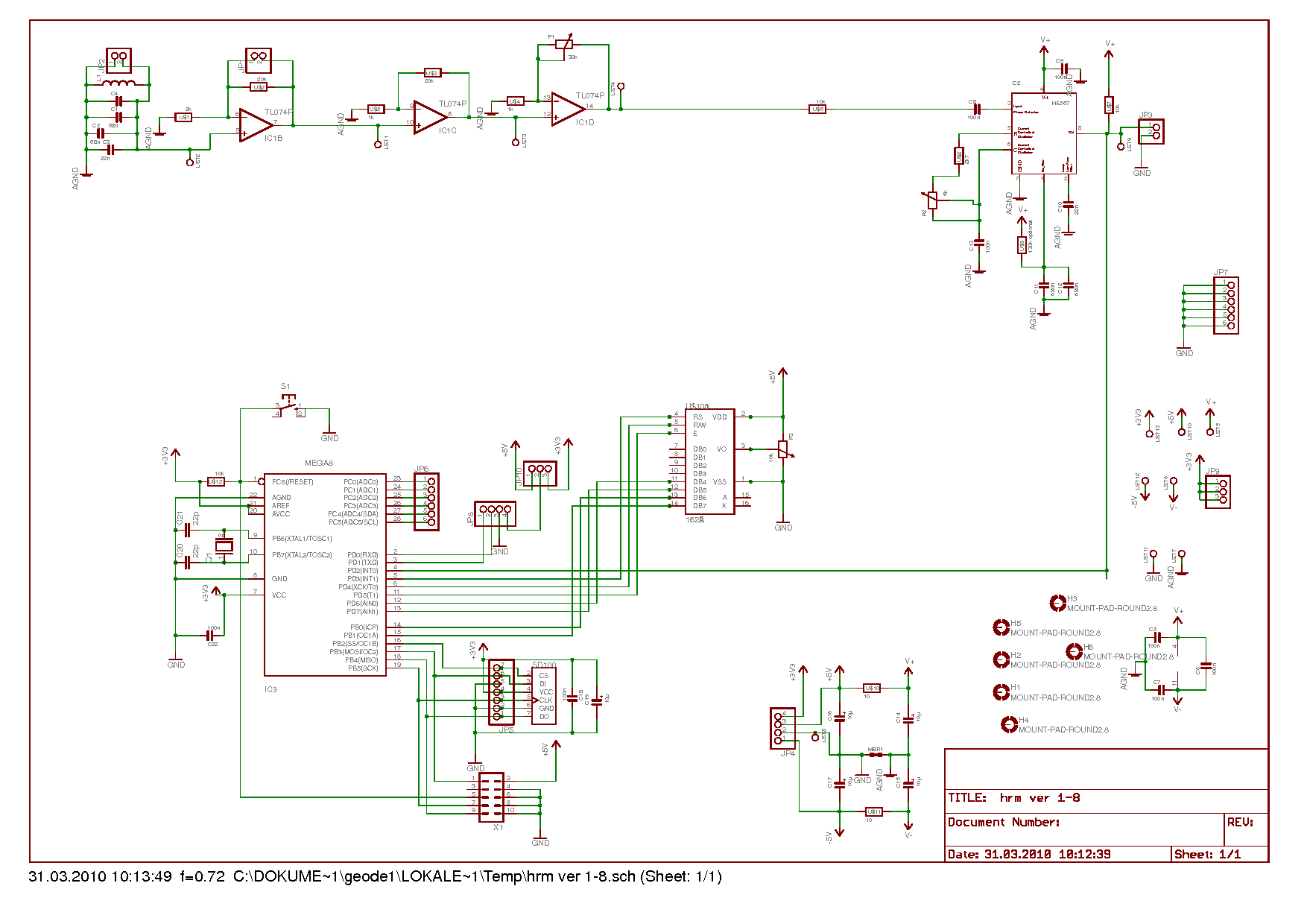
Pete K. schrieb:
> In der lcd.h ist XTAL auf 8Mhz gesetzt. Stimmt das mit FCPU überein?
> Werden die delay.h Routinen benutzt?
> Poste mal Deine Schaltung.
> Das LCD funktioniert mit 3,3V?

hallo

fcpu = 8mhz
die delay.h wird nicht benutzt, läuft alles über timer oder "system
time"
das lcd, läuft mit 5V für kontrast, ansprechen tue ich es jedoch direkt
mit den megaxxx mit 3,3V

hab den datentraffic an den lcd pins mitn oszi gemessen, beim mega8
werden daten hinübergeschaufelt, beim mega328 ist stille
ich glaube ich weiß wo der fehler liegt.

und zwar habe ich einen parallel programmer, und mit meiner avrdude vers
kann ich keinen mega328 programmieren.
habe avrisp zum programmieren gefunden, funkt auch ganz gut.
jedenfalls habe ich noch aus alten zeiten bascom, was ich auch teilweise
für die fuse zum setzten verwende (da kenn mich auch), jedenfalls wenn
ich mit bascom das hex file zum mega328 sende dann bekomme ich in
derzeit in 95% der fälle einen fehler nach dem vertify, wo er sagt das
ein wert nicht stimmt (avr isp hat nur programmiert und kein vertify
gemacht).
und jedesmal wenn ich diesen fehler bekomme hängt der avr, wenn kein
fehler kommt dann läuft das programm.

hab mir letztens eh einen avr mkII bestellt, mit dem kann man vom
avrstudio aus gleich programmieren, hoffe es klappt dann besser.
jedenfalls danke! und ich berichte sobald ich den neuen programmer habe.
Bitte melde dich an um einen Beitrag zu schreiben. Anmeldung ist kostenlos und dauert nur eine Minute.
Bestehender Account
Schon ein Account bei Google/GoogleMail? Keine Anmeldung erforderlich!
Mit Google-Account einloggen
Mit Google-Account einloggen
Noch kein Account? Hier anmelden.