Moin,
also ich habe folgendes Problem ich muss ein Zähler realieseiren der von
0 bis 6 zählt also würden ja 3 FF reichen aber der Knackpunkt an der
sache ist das 6 Ausgangsbits bei jedem Takt gesetzt werden müssen.. Den
Takt soll der Zähler von einer Lischtschranke bekommen, also wenn sie
unterbochen wird dann soll er einen Schritt weiter zählen.

hier mal die Wahrheitstabelle

Takt Q0 Q1 Q2 Q3 Q4 Q5
  1 | 0| 0| 0| 0| 0| 0
  1 | 0| 0| 0| 1| 0| 0
  1 | 0| 0| 0| 1| 1| 0
  1 | 0| 0| 0| 1| 1| 1
  1 | 1| 0| 0| 1| 1| 1
  1 | 1| 1| 0| 1| 1| 1
  1 | 1| 1| 1| 1| 1| 1

habe schon mal was in WinCupl probiert aber keine Ahung ob das so
stimmt..

Name      ;
Partno    CA0018;
Date      12/19/99;
Revision  02;
Designer  ;
Company   Logical Devices, Inc.;
Assembly  None;
Location  None;
Device    g16v8a;


/**  Inputs  **/

Pin 1        = clk;             /* Counter clock                */
Pin 2        = clr;             /* Counter clear input          */
Pin 3        = dir;             /* Counter direction input      */
Pin 11       = !oe;             /* Register output enable       */

/**  Outputs  **/

Pin [12..17] = [Q5..0];         /* Counter outputs              */
Pin 19 = carry;                 /* Ripple carry out             */

/** Declarations and Intermediate Variable Definitions **/

field count = [Q5..0];          /* declare counter bit field */
$define S0 'b'000000              /* define counter states */
$define S1 'b'000100
$define S2 'b'000110
$define S3 'b'000111
$define S4 'b'100111
$define S5 'b'110111
$define S6 'b'111111


field mode = [clr,dir];         /* declare mode control field */
up = mode:0;                    /* define count up mode */
down = mode:1;                  /* define count down mode */


clear = mode:[2..3];            /* define count clear mode */

/** Logic Equations **/

Sequenced count {                       /* free running counter */

present S0      if up           next S1;
                if down         next S6;
                if clear        next S0;
                if down         out carry;
present S1      if up           next S2;
                if down         next S0;
                if clear        next S0;
present S2      if up           next S3;
                if down         next S1;
                if clear        next S0;
present S3      if up           next S4;
                if down         next S2;
                if clear        next S0;
present S4      if up           next S5;
                if down         next S3;
                if clear        next S0;
present S5      if up           next S6;
                if down         next S4;
                if clear        next S0;
present S6      if up           next S0;
                if down         next S5;
                if clear        next S0;
      if up           out carry;

                        /* assert carry output */
}
eine schnelle antwort wäre echt top da ich gerde überhaupt kein plan
habe wie das umsetzen kann...
Die einfachste Überprüfung ist die Simulation. Ich kenne wincupl nicht
aber Simulation gab es schon immmer mit allen GAL Entwicklungsprogrammen
(ABEL ....).
ja es muss so funktionieren aber die simulation ist kackt voll ab so wie
das komplette wincupl-programm^^ ich glaube ich brenn den schitt einfach
mal auf den GAL und dann werde ich ja sehen ob es geht...
Das ist nur der Quelltext - was hat WinCUPL daraus gemacht? Wie sehen
die logischen Gleichungen aus?
Man kann auch aus dem JEDEC-File wieder Abel-Gleichungen erzeugen
lassen, dazu gibts JED2ABL.exe oder JED2AHDL.exe
Angehängte Dateien:
-

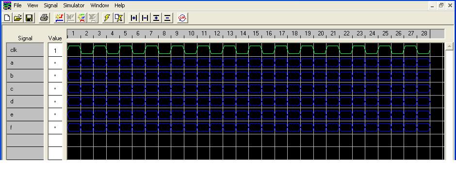
LichtschrZaehl-Sim.JPG
77 KB
Moin erstmal danke für die antworten... habe es jetzt hinbekommen nach
dem ich Wincupl mehrmals deinstalliert habe und geühlte 100 neue
projekte erstllt habe gibts jetzt keine fehler mehr und die simulation
funktioniert auch^^

die Simulation habe ich mal angehängt....

habe den code noch bissel vereinfacht das ich den rest und up und down
count garnicht brauche..

hier der code:
Name     LichtSchrZaehl ;
PartNo   00 ;
Date     09.06.2010 ;
Revision 99 ;
Designer Christian Schulz ;
Company  bmt09 ;
Assembly None ;
Location  ;
Device   g20v8a ;

/* INPUT-PINS */
PIN  1 = clk;

/* OUTPUT-PINS */
PIN  15 = a;
PIN  16 = b;
PIN  17 = c;
PIN  18 = d;
PIN  19 = e;
PIN  20 = f;

field count = [a,b,c,d,e,f];

$define S0 'b'000000
$define S1 'b'000100
$define S2 'b'000110
$define S3 'b'000111
$define S4 'b'100111
$define S5 'b'110111
$define S6 'b'111111

Sequenced count{
present S0  next S1;
present S1  next S2;
present S2  next S3;
present S3  next S4;
present S4  next S5;
present S5  next S6;
present S6  next S0;
}


und noch mal dein JED-Datei:

CUPL(WM)        5.0a  Serial# 60008009
Device          g20v8ms  Library DLIB-h-40-3
Created         Wed Jun 09 00:40:39 2010
Name            LichtSchrZaehl
Partno          00
Revision        99
Date            09.06.2010
Designer        Christian Schulz
Company         bmt09
Assembly        None
Location
*QP24
*QF2706
*G0
*F0
*L00640 11111111111111011101110111101111
*L00672 11011111111111111111111111011101
*L00704 11101110111011110000000000000000
*L00960 11111111111111011101110111101101
*L00992 11011111111111111111111011111101
*L01024 11101110111011111111111111111101
*L01056 11011101111011101111111100000000
*L01280 11111111111111101110111111101110
*L01312 11101111111111111111111111011101
*L01344 11101110111011111111111111111101
*L01376 11011101111011111101111100000000
*L01600 11111111111111011101110111101101
*L01632 11011111000000000000000000000000
*L01920 11111111111111011101110111101111
*L01952 11011111000000000000000000000000
*L02240 11111111111111011101110111101101
*L02272 11011111111111111111110111011101
*L02304 11101110111111110000000000000000
*L02560 00111111001100000011000000100000
*L02624 00000000110000001111111111111111
*L02656 11111111111111111111111111111111
*L02688 111111111111111101
*C3A91
*FE6B


müsste doch dann auch so in der praxis funktionieren wenn ich das auf
nen gal gebrannt habe oder und den takt mittels unterbrechung der
lichtschranke erzeuge oder??


mfg Schulle
Angehängte Dateien:
-

LichtschrZaehl-Sim.JPG
77 KB
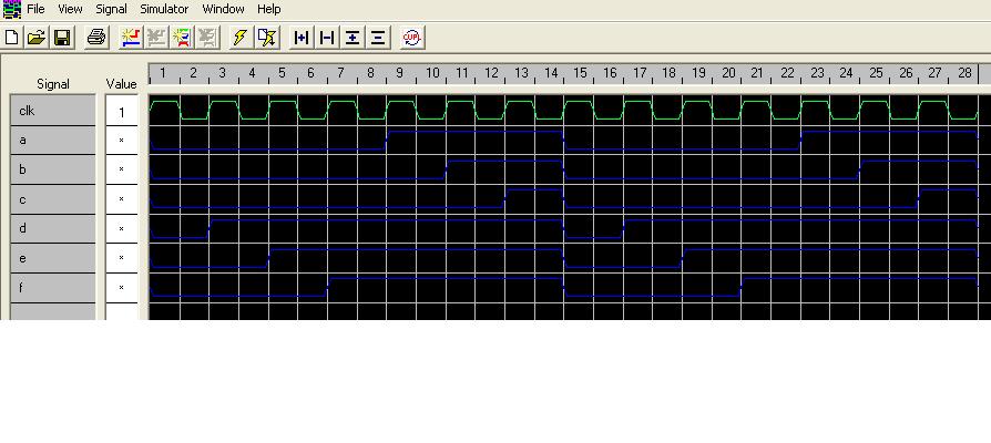
upps hätte die siumlation auch mal simulieren lassen müssen^^
hier noch mal das richtige...
Ich bin zwar sicher, dass Wincupl auch lesbare Texte erzeugt, aber hier
gibt es das JEDEC zu Abel-Umwandlungsprogramm:
http://www.atmel.com/dyn/products/tools.asp?family_id=653
"JED2AHDL.ZIP Contains JEDEC-to-ABEL de-compiler"
So...
mit JED2AHDL ergeben sich folgende logische Gleichungen:

MODULE WinCupl
"Created by JED2AHDL ABEL 6.00 on Thu Jun 10 08:29:53 19;0

TITLE
'
 '

        WinCupl device 'p20v8s';

"Pin and Node Declarations
    Pin01,  Pin02,  Pin03,  Pin04  PIN   1, 2, 3, 4;
    Pin05,  Pin06,  Pin07,  Pin08  PIN   5, 6, 7, 8;
    Pin09,  Pin10,  Pin11,  Pin12  PIN   9,10,11,12;
    Pin13,  Pin14,  Pin15,  Pin16  PIN  13,14,15,16;
    Pin17,  Pin18,  Pin19,  Pin20  PIN  17,18,19,20;
    Pin21,  Pin22,  Pin23,  Pin24  PIN  21,22,23,24;

  Pin15,Pin16,Pin17,Pin18,Pin19,Pin20 ISTYPE 'Neg';
  Pin15,Pin16,Pin17,Pin18,Pin19,Pin20,Pin21,Pin22 ISTYPE 'Com';
  Pin15,Pin16,Pin17,Pin18,Pin19,Pin20,Pin21,Pin22 ISTYPE 'Invert';

  X,K,Z,C,P,U,D = .X.,.K.,.Z.,.C.,.P.,.U.,.D.;

EQUATIONS

!Pin15 = !(Pin21  & Pin20  & Pin17  & !Pin16  & Pin15  &
               Pin14
             # Pin21  & Pin20  & Pin17  & !Pin16  & !Pin15 );
Pin15.OE = 1;

!Pin16 = !(Pin21  & Pin20  & Pin17  & !Pin16  & Pin14 );
Pin16.OE = 1;

!Pin17 = !(Pin21  & Pin20  & Pin17  & !Pin16  & Pin15  &
               Pin14 );
Pin17.OE = 1;

!Pin18 = !(!Pin21  & !Pin20  & !Pin16  & !Pin15  & !Pin14
             # Pin20  & Pin17  & !Pin16  & !Pin15  & !Pin14
             # Pin21  & Pin20  & Pin17  & !Pin16  & Pin14 );
Pin18.OE = 1;

!Pin19 = !(Pin21  & Pin20  & Pin17  & !Pin16  & Pin15  &
               Pin14
             # !Pin21  & Pin17  & !Pin16  & !Pin15  & !Pin14
             # Pin21  & Pin20  & Pin17  & !Pin16  & !Pin15 );
Pin19.OE = 1;

!Pin20 = !(Pin21  & Pin20  & Pin17  & !Pin16  & Pin14
             # Pin20  & Pin17  & !Pin16  & !Pin15  & !Pin14 );
Pin20.OE = 1;

!Pin21 = ( 0 );
Pin21.OE = 0;

!Pin22 = ( 0 );
Pin22.OE = 0;


TEST_VECTORS
([]->[])


END


Was mir als erstes auffällt, da sind keine Register drin, ohne Register
auch keine Zähler.

Im Anhang das Programm und die Device-Dateien, die fehlen bei Atmel
noch. Ich habe eine DeviceListe.txt dazugefügt, da stehen alle
decodierbaren Device-Namen drin, mit "p20V8" kommt eine Fehlermeldung,
aber mit dem p20v8s läuft es anstandslos durch, muß aber noch nicht
heißen, das es fehlerfrei ist.
Dankeschön...

habe es jetzt mit nem GAL22V10 gemacht und funktioniert auch in der
Praxis aber halt nur wenn ich einen generierten takt an den ckl-Eingang
anlege... mit der lichtschranke haut es nicht hin...
Bitte melde dich an um einen Beitrag zu schreiben. Anmeldung ist kostenlos und dauert nur eine Minute.
Bestehender Account
Schon ein Account bei Google/GoogleMail? Keine Anmeldung erforderlich!
Mit Google-Account einloggen
Mit Google-Account einloggen
Noch kein Account? Hier anmelden.