
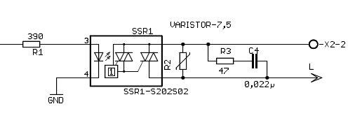
Ich habe folgendes problem mit dem sharp SSR 1-S202S02
Meine schaltung ist wie im Anhang.
Ich schalte einen motor ca. 1 A
Ich habe aber ein IT Netz mit Phase zu Phase 230V.
Das Halbleiterrelais schaltet nach ein paar schaltungen komplett durch.
Der Motor läuft weiter.
Ist das Halbleiterralais für Phase zu Phase 230V überhaupt ausgelegt?
Ich habe jetzt zum testen ein Trafo vorgeschaltet dann habe ich Phase zu
N 230V.


Hat jemand eine Idee?

RC glied zu klein dimensioniert?

Danke im vorraus
Angehängte Dateien:
-

Sharp_Halbleiterrelais.gif
4,8 KB
Design guide

In order for the SSR to turn off, the triggering current (lF) must be
0.1mA or less.
When the input current (IF) is below 0.1mA, the output Triac will be in
the open circuit mode. However, if the voltage across the Triac, VD,
increases faster than rated dV/dt, the Triac may turn on. To avoid this
situation, please incorporate a snubber circuit. Due to the many
different types of load that can be driven, we can merely recommend some
circuit vales to start with: Cs=0.022µF and Rs=47Ω. The operation of the
SSR and snubber circuit should be tested and if unintentional switching
occurs, please adjust the snubber circuit component values accordingly.

(...)

Particular attention needs to be paid when utilizing SSRs that
incorporate zero crossing circuitry. If the phase difference between the
voltage and the current at the output pins is large enough, zero
crossing type SSRs cannot be used. The result, if zero crossing SSRs are
used under this condition, is that the SSR may not turn on and off
irregardless of the input current. In this case, only a non zero cross
type SSR should be used in combination with the above mentioned snubber
circuit selection process.
Bitte melde dich an um einen Beitrag zu schreiben. Anmeldung ist kostenlos und dauert nur eine Minute.
Bestehender Account
Schon ein Account bei Google/GoogleMail? Keine Anmeldung erforderlich!
Mit Google-Account einloggen
Mit Google-Account einloggen
Noch kein Account? Hier anmelden.