Hallo Allerseits,

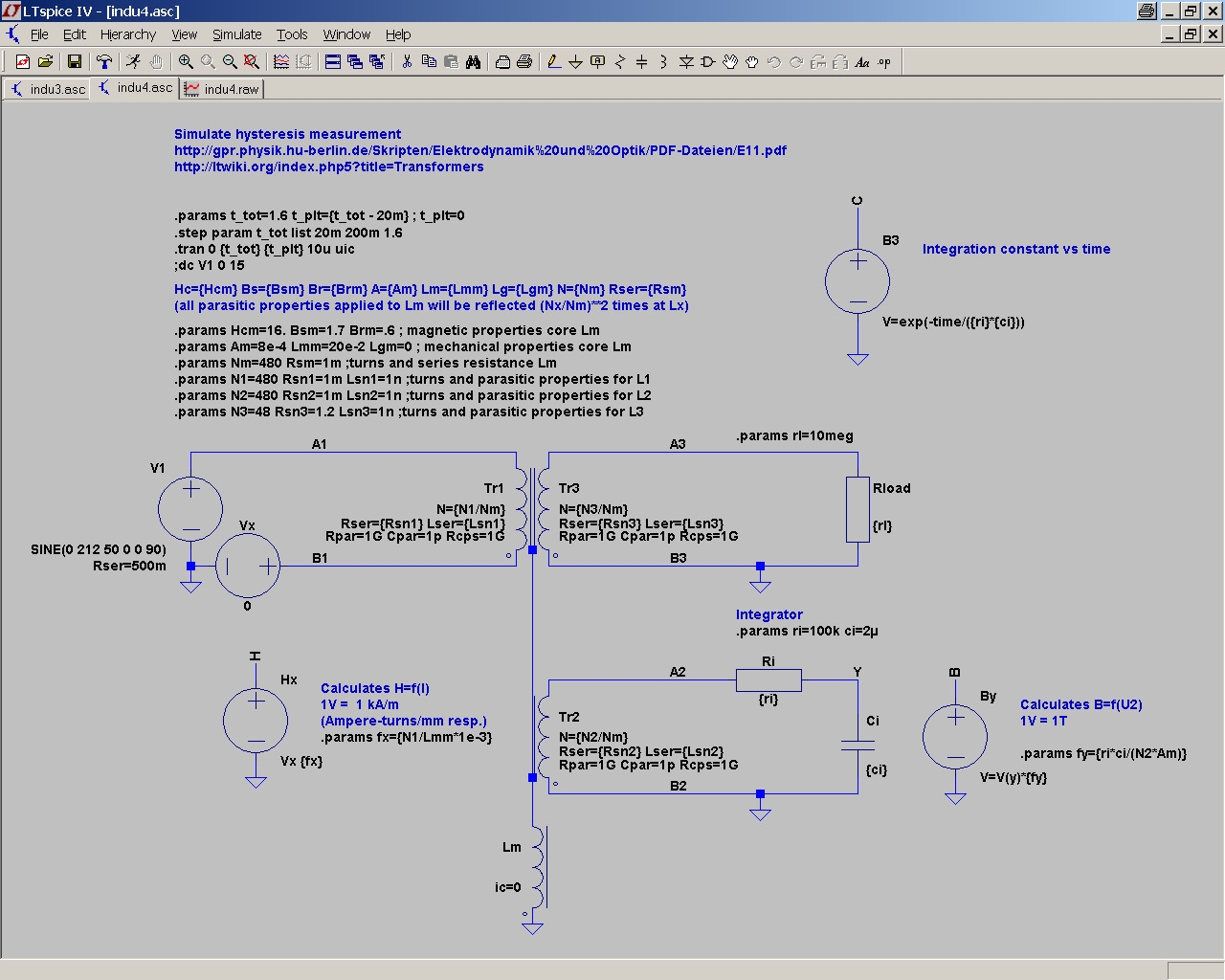
um LTspice etwas besser kennenzulernen, habe ich mir unter anderem einen
Transformator "gebaut".
Messaufbau ist nach
http://gpr.physik.hu-berlin.de/Skripten/Elektrodynamik%20und%20Optik/PDF-Dateien/E11.pdf,
während das Innenleben von Tr1-3 eine leichte Modifikation von
http://ltwiki.org/index.php5?title=Transformers darstellt (siehe auch
indu3.asc im zip).
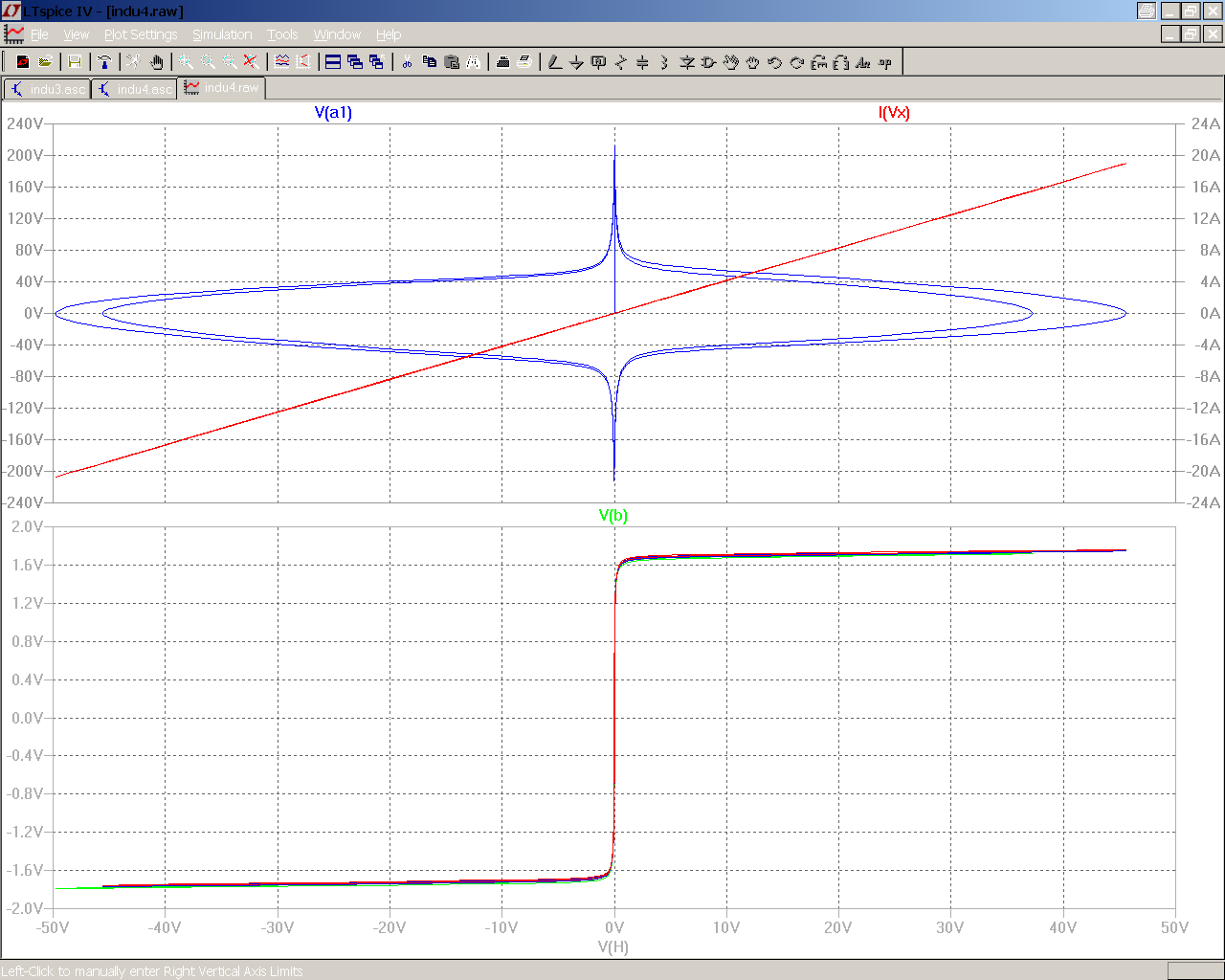
Das ganze funktioniert eigentlich wie erwartet (indu4_1.png), auch wenn
die berechneten Werte etwas von den Modellparametern abweichen (Br
0.6->0.66; Hc 16->21).

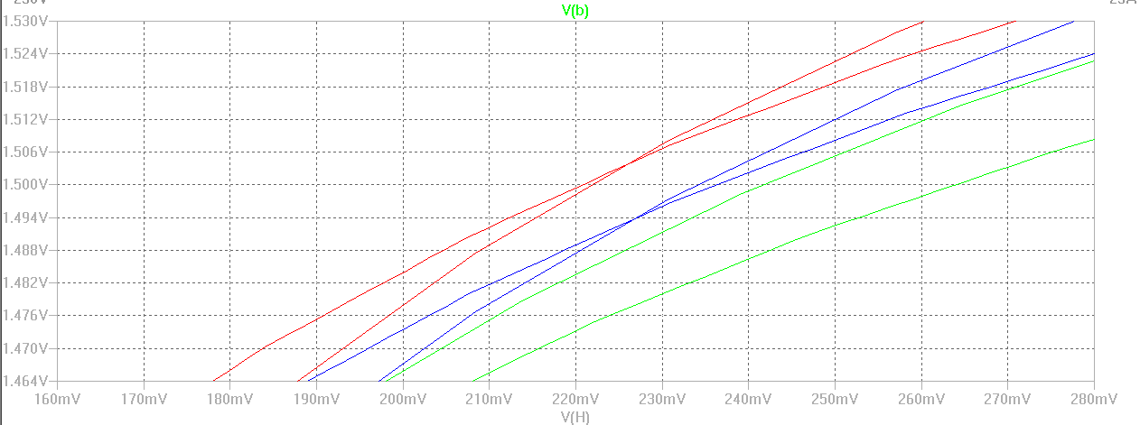
Was mich jedoch irritiert ist die Überschneidung des aufsteigenden und
abfallend Astes zwischen 220 und 230 A/m (indu4_2.png), was meiner
Meinung nach nicht unbedingt einer anständigen, handelsüblichen
Hysteresekurve entspricht.

Hat hier jemand eine Erklärung für dieses Verhalten?

Ich wär auch an realen Daten - die magnetischen Parameter hab ich mir
aus den Fingern gesaugt - eines Ringkerntransformators im
Leistungsbereich von 300-1500VA interessiert. Damit möchte ich noch ein
paar Varianten von Einschaltstrombegrenzungen (Widerstand, NTC,
Vormagnetisierung) simulieren, bevor ich zu frequenzabhängigen
Eigenschaften von Lm übergehe.

Danke

trafo
Hallo trafo,

Man kann nicht B und H von der Außenseite des Kerns berechnet. Einige
der Ströme durch die parasitäre Widerstände und Kapazitäten und die
Spannung an den Leitungen außen ist nicht identisch mit dem auf und
durch den Chan Kern.

Uebrigens, ich schrieb den Transformator-Abschnitt in der LTwiki und
wäre daran interessiert, Ihr Professor (oder die Person, die auf diesem
in Berlin) zu emailen. Ist diese Institution einer Universität oder
einem College? (Ich bin Amerikaner und bin nicht sehr vertraut mit wie
Hochschulausbildung in Deutschland organisiert ist.) -- a.s.
Hallo analogspiceman

Thanks for your reply. So you think that I have underestimated the
influence of the remaining parasitic properties - I will check this.

I've found the description of the hysteresis measurement doing a web
search. It is part of the basic lessons for experimental physics held by
Dr. Uwe Müller at the Humboldt University of Berlin in 2005.
Being not related to this Institute (or to any other) I'm not able to
help you contacting him but I've found his mail adress on their website
(http://gpr.physik.hu-berlin.de/Kontakte/Kontakte.html).

https://en.wikipedia.org/wiki/Humboldt_University_of_Berlin


wbr

trafo
Hello again trafo,

Now you have confused me ... twice.

First off, your English is so good I can't tell which is your native
toungue.  I can read the German forums well enough, but it is an effort
for me not to write like an idiot in German.

Then, secondly, since I could find no SPICE examples on the Humbolt
Unversity website, I must assume that you created all the LTspice files
yourself.  These are quite well done and reveal an exceptional
understanding of both LTspice and of the workings of transformers
mathmatically (as well as practically).

If you originated these files, then not only is my hat off to you (the
translation of the Chan model to a flux statement is very impressive),
but then I am confused that you would not recognize the effect of the
transformer's parasitic elements in disturbing the calculation of B and
H within its idealized, mutually coupled core.  (I suppose such things
easily happen if working entirely alone.)

I have written about your postings here over on the LTspice Yahoo group:
http://tech.groups.yahoo.com/group/LTspice/message/54929
Please join if you have not already.

Regards -- analogspiceman

PS: One thing to keep in mind when writing models for LTspice: the most
convergence friendly models avoid pure voltage sources (except as
zero-volt current sensors) and express those sources instead in their
equivalent Nortonized form (current source type devices in parallel with
an impedance).  The ideal active device for LTspice is a voltage
controlled current source driving into an impedance that includes at
least a small amount of linear shunt capacitance.
Hallo analogspiceman

sorry for the delay, but it was friday evening...
And no - I'm realy, realy not a student.

Indeed I carried out a similar experiment during my education more than
30 years ago but back then I'm interested mostly in other curves - not
to say boobies.

For shure, I have created the schematic and the related subcirciut and
symbols by myself but the essential information therein is all covered
by your wiki article and the postings of Mike Engelhardt, so there is
not much of my work worth to mention. I'm very glad about your comments
on my circiut, because as stated in the opening post these are my first
steps in using LTspice.

Whithout your hint I wouldn't have thought twice about checking the
parasitic influence because my 'feeling' says that they are too low in
relation to the main inductance.

With regard to joining the yahoo group - I saw a lot of links pointing
there so I think it could be worth for solving real problems, but I'm
feeling slightly uncomfortable with closed platforms requiring
registration even just for reading. Personally I prefer usenet
communication or open forums like the mikrocontroller.net.

Thanks again and best regards

trafo
Hallo trafo,

Ich hoffe, Sie besuchen periodisch diese Internetseite.
Ja, es sind mehr als 4 Jahre gegangen.

So, das Chan-Model ist genau. Ich habe die gleiche Übung vor mehr als 40
Jahre in Bulgarien gemacht. Dann benutzten wir die übliche Oszilloskope,
die keine bessere als 2 % Genauigkeit erreichten. Wenn ich richtig
verstehe, Sie brauchen eine höhere Genauigkeit vom Chan-Model. Ja,
richtig, das ist ein Simulationsprogramm.

Die Ursache, keine gute Genauigkeit zu erreichen, ist in Ihrem RC-Glied,
der Integrator. Er ist nicht ideal, er dreht zum Beispiel die Phase nur
auf 89 Grad, aber nicht auf 90, und belastet auch den Transformator.
Benutzen Sie, bitte 10meg und 200n uns Sie erreichen eine höhere
Genauigkeit. Wenn Sie auch einen idealen Verstärker (E in LTSpice) und
einen idealen Integrator (mit dem Kondensator in der Rückkopplung)
benutzen, dann erhalten Sie noch bessere Ergebnisse.

73! Go Go

 indu4.png
(37 KB)
indu4.png
(37 KB)
 indu4_1.png
(29 KB)
indu4_1.png
(29 KB)
 indu4_2.png
(8,9 KB)
indu4_2.png
(8,9 KB)