Hallo,

Ich bin dabei den 9DOF Sensor Stick von Sparkfun
(https://www.sparkfun.com/products/10724) mit dem MSP430F149 zu nutzen.
Ich verwende Code Composer Studio V5.3.
Zur Zeit möchte ich gerne einfach nur das Beispiel aus dem Datenblatt
des Magnetsensors (HMC5883L:
http://dlnmh9ip6v2uc.cloudfront.net/datasheets/Sensors/Magneto/HMC5883L-FDS.pdf)
ausprobieren.
Hier der Auszug aus dem Datenblatt:
"Below is an example of a (power-on) initialization process for
“single-measurement mode”:

1. Write CRA (00) – send 0x3C 0x00 0x70 (8-average, 15 Hz default or any
other rate, normal measurement)
2. Write CRB (01) – send 0x3C 0x01 0xA0 (Gain=5, or any other desired
gain)
3. For each measurement query:
   Write Mode (02) – send 0x3C 0x02 0x01 (Single-measurement mode)
   Wait 6 ms or monitor status register or DRDY hardware interrupt pin
   Send 0x3D 0x06 (Read all 6 bytes. If gain is changed then this data
set
   is using previous gain)
   Convert three 16-bit 2’s compliment hex values to decimal values and
   assign to X, Z, Y, respectively."

Und hier ist mein Code:

Main:
1 | #include <msp430.h>
|
2 | #include "i2c.h"
|
3 |
|
4 | #define GND BIT1 //Px.1
|
5 | #define Vcc BIT4 //Px.4
|
6 | #define SDA BIT2 //Px.2
|
7 | #define SCL BIT3 //Px.3
|
8 | #define mag_write 0x3C //Magnetometer write
|
9 | #define mag_read 0x3D //Magnetometer read
|
10 |
|
11 |
|
12 | int main(void)
|
13 | {volatile int xh=0, xl=0, yh=0, yl=0,zh=0, zl=0, x=0, y=0, z=0; volatile int w=0;
|
14 | WDTCTL = WDTPW | WDTHOLD; // Stop watchdog timer
|
15 |
|
16 | P1DIR |= Vcc; //bit 4
|
17 | P1DIR |= GND; //bit 1
|
18 | P1OUT |= Vcc;
|
19 | P1OUT &=~ GND;
|
20 | P1DIR |= SDA; //bit 2
|
21 | P1DIR |= SCL; //bit 3
|
22 |
|
23 | /////////////////////////////////////////////
|
24 | ////////Write Configuration Register A///////
|
25 | /////////////////////////////////////////////
|
26 |
|
27 | i2c_start(); // start sequence (Magnetometer auswählen)
|
28 | if(i2c_tx(mag_write)) // I2C address with R/W bit clear
|
29 | {
|
30 | if(i2c_tx(0x00))
|
31 | {
|
32 | i2c_tx(0x70);
|
33 | }
|
34 | }
|
35 | i2c_stop();
|
36 | /////////////////////////////////////////////
|
37 | ////////Write Configuration Register B///////
|
38 | /////////////////////////////////////////////
|
39 |
|
40 | i2c_start(); // start sequence (Magnetometer config)
|
41 | if(i2c_tx(mag_write)) // I2C address with R/W bit clear
|
42 | {
|
43 | if(i2c_tx(0x01))
|
44 | {
|
45 | i2c_tx(0xA0);
|
46 | }
|
47 | }
|
48 | i2c_stop();
|
49 | /////////////////////////////////////////////
|
50 | /////////////Write Mode Register/////////////
|
51 | /////////////////////////////////////////////
|
52 |
|
53 | i2c_start(); // start sequence (Magnetometer messen)
|
54 | if(i2c_tx(mag_write)) // I2C address with R/W bit clear
|
55 | {
|
56 | if(i2c_tx(0x02))
|
57 | {
|
58 | i2c_tx(0x01);
|
59 | }
|
60 | }
|
61 |
|
62 | i2c_dly();
|
63 | wait(32000);
|
64 | i2c_stop();
|
65 |
|
66 | /////////////////////////////////////////////
|
67 | //////////Read Data Output Register//////////
|
68 | /////////////////////////////////////////////
|
69 |
|
70 | i2c_start(); // start sequence (Magnetometer auslesen)
|
71 | if(i2c_tx(mag_read)) // SRF08 I2C address with R/W bit clear
|
72 | {
|
73 | if(i2c_tx(0x06))
|
74 | {
|
75 | xh = i2c_rx(1); //low und high byte von X
|
76 | i2c_dly();
|
77 | xl = i2c_rx(1);
|
78 | i2c_dly();
|
79 | zh = i2c_rx(1); //low und high byte von Z
|
80 | i2c_dly();
|
81 | zl = i2c_rx(1);
|
82 | i2c_dly();
|
83 | yh = i2c_rx(1); //low und high byte von Y
|
84 | i2c_dly();
|
85 | yl = i2c_rx(1);
|
86 | }
|
87 | }
|
88 | i2c_stop(); // stop sequence
|
89 |
|
90 |
|
91 | /////////////////////////////////////////////
|
92 |
|
93 |
|
94 | x = xl|(xh<<=8);
|
95 | y = yl|(yh<<=8);
|
96 | z = zl|(zh<<=8);
|
97 |
|
98 | w = atan2(y,x)*(180 / 3.14159265) +180;
|
99 |
|
100 | return 0;
|
101 | }
|
Und hier die i2c.c:
1 | #include<msp430.h>
|
2 |
|
3 | #define SDA BIT2 //Px.2
|
4 | #define SCL BIT3 //Px.3
|
5 |
|
6 | //Auszüge aus http://www.robot-electronics.co.uk/acatalog/I2C_Tutorial.html
|
7 |
|
8 | ////////////////////////////
|
9 | ///////I2C-Funktionen///////
|
10 | ////////////////////////////
|
11 |
|
12 |
|
13 | void i2c_dly(void) //clear-Funktion
|
14 | {
|
15 | }
|
16 |
|
17 | void wait(unsigned int i)
|
18 | {int k;
|
19 | for(k=0;k<=i;k++);
|
20 | for(k=0;k<=i;k++);
|
21 | for(k=0;k<=i;k++);
|
22 | }
|
23 |
|
24 | void i2c_start(void) // i2c start bit sequence
|
25 | {
|
26 | P1OUT|=SDA;
|
27 | i2c_dly();
|
28 | P1OUT|=SCL;
|
29 | i2c_dly();
|
30 | P1OUT&=~SDA;
|
31 | i2c_dly();
|
32 | P1OUT&=~SCL;
|
33 | i2c_dly();
|
34 | }
|
35 |
|
36 | void i2c_stop(void) // i2c stop bit sequence
|
37 | {
|
38 | P1OUT&=~SDA;
|
39 | i2c_dly();
|
40 | P1OUT|=SCL;
|
41 | i2c_dly();
|
42 | P1OUT|=SDA;
|
43 | i2c_dly();
|
44 | }
|
45 |
|
46 | unsigned char i2c_rx(char ack) //read
|
47 | {
|
48 | char x, d=0;
|
49 | P1OUT|=SDA;
|
50 | for(x=0; x<8; x++)
|
51 | {
|
52 | d <<= 1;
|
53 |
|
54 | i2c_dly();
|
55 | if(P1IN&SDA) d |= 1;
|
56 | P1OUT&=~SCL;
|
57 | }
|
58 | if(ack) P1OUT&=~SDA;
|
59 | else P1OUT|=SDA;
|
60 | P1OUT|=SCL;
|
61 | i2c_dly(); // send (N)ACK bit
|
62 | P1OUT&=~SCL;
|
63 | P1OUT|=SDA;
|
64 | return d;
|
65 | }
|
66 |
|
67 | int i2c_tx(unsigned char d) //send
|
68 | {
|
69 | char x;
|
70 | static int b;
|
71 | for(x=8; x; x--)
|
72 | {
|
73 | if(d&0x80) P1OUT|=SDA;
|
74 | else P1OUT&=~SDA;
|
75 | P1OUT|=SCL;
|
76 | d <<= 1;
|
77 | P1OUT&=~SCL;
|
78 | }
|
79 | P1OUT|=SDA;
|
80 | P1OUT|=SCL;
|
81 | i2c_dly();
|
82 | b = P1IN&SDA; // possible ACK bit
|
83 | P1OUT&=~SCL;
|
84 | return b;
|
85 | }
|
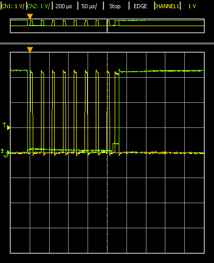
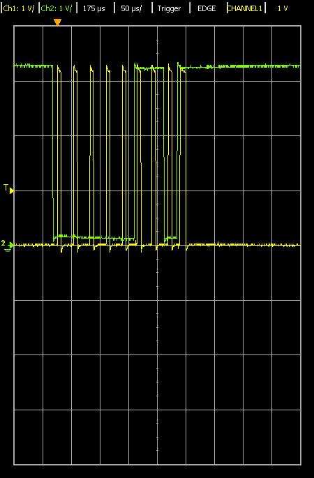
Mein Problem ist, dass ich vom Sensor beim Auslesen der 6 Bytes nur 6
mal 0xFF zurück bekomme. Dies ist meine erste Erfahrung mit I2C und ich
weis nicht, was ich falsch mache. Mein Anhaltspunkt ist das Schirmbild
des Oszilloskops. Hier ist das Ack meiner Meinung nach nicht genau
erkennbar. Bzw. SDA bleibt bei jeder Übertragung für kurze Zeit auf ca
0.4 V. Das Schirmbild habe ich mal angehängt. CH1 ist hier SCL und CH2
SDA. Ubertragen wird hier 0x00 vom Master (MSP430) zum Slave (Sensor).

Kann mir jemand helfen? Danke schonmal im Vorraus.

Gruß