VHDL Timer & PWM

OP #4026606
Lesenswert?

Hallo zusammen,

ich habe meine Timer + PWM Schaltung fertig gemacht und möchte die im 
nächsten Schritt in einen IP-Core gießen um die dann per AXI in meinem 
Zynq zu verwenden.
1
----------------------------------------------------------------------------------
2
-- Company: 
3
-- Engineer: 
4
-- 
5
-- Create Date:         10.02.2015 11:18:22
6
-- Design Name: 
7
-- Module Name:         PWM - PWM_Arch
8
-- Project Name: 
9
-- Target Devices: 
10
-- Tool Versions: 
11
-- Description:         Simple Timer & PWM Module
12
-- 
13
-- Dependencies: 
14
-- 
15
-- Revision:
16
-- Revision 0.01 - File Created
17
-- Additional Comments:
18
-- 
19
----------------------------------------------------------------------------------
20

21
library IEEE;
22
use IEEE.STD_LOGIC_1164.ALL;
23
use IEEE.NUMERIC_STD.ALL;
24
use IEEE.STD_LOGIC_unsigned.all;
25

26
-- Uncomment the following library declaration if instantiating
27
-- any Xilinx leaf cells in this code.
28
--library UNISIM;
29
--use UNISIM.VComponents.all;
30

31
entity Timer is
32
    Generic (   Width : integer := 8 );
33
    Port (      Clock_In : in STD_LOGIC;
34
                Prescaler : in STD_LOGIC_VECTOR(2 downto 0);
35
                Preload : in STD_LOGIC_VECTOR(Width - 1 downto 0);
36
                Capture : in STD_LOGIC_VECTOR(Width - 1 downto 0);
37
                Reset : in STD_LOGIC := '1';
38
                PWM_Enable : in STD_LOGIC := '0';
39
                PWM_Inv : in STD_LOGIC := '0';
40
                Compare : out STD_LOGIC := '0';
41
                Overflow : out STD_LOGIC := '0';
42
                PWM : out STD_LOGIC := '0';
43
                Clock_Out : out STD_LOGIC); 
44
end Timer;
45

46
architecture Timer_Arch of Timer is
47

48
    signal Clock_Intern : std_logic;
49
    signal Counter      : std_logic_vector(Width - 1 downto 0) :=  (others => '0');
50
    signal Counter_Timer: std_logic_vector(Width - 1 downto 0) :=  (others => '0');
51

52
begin
53

54
    -- Prescaler
55
    process(Clock_In, Reset, Prescaler)
56
    begin
57
        if(Reset = '1') then
58
            Counter <= (others => '0');
59
        elsif(rising_edge(Clock_In)) then
60
            Counter <= Counter + 1;
61
        end if;
62
        
63
        case Prescaler is
64
            when "001" => Clock_Intern <= Counter(1);
65
            when "010" => Clock_Intern <= Counter(2);
66
            when "011" => Clock_Intern <= Counter(3);
67
            when "100" => Clock_Intern <= Counter(4);
68
            when "101" => Clock_Intern <= Counter(5);
69
            when "110" => Clock_Intern <= Counter(6);
70
            when "111" => Clock_Intern <= Counter(7);
71
            when others => Clock_Intern <= Counter(0);
72
        end case;        
73
    end process;
74
    
75
    process
76
    begin    
77
        wait until(rising_edge(Clock_Intern)); 
78
            Counter_Timer <= Counter_Timer + 1;
79

80
        if(PWM_Enable = '0') then
81
        
82
            -- Compare Interrupt
83
            if(Counter_Timer(Width - 1 downto 0) > (Preload(Width - 1 downto 0) - 1)) then
84
                Compare <= '1';
85
                Counter_Timer <= (others => '0');
86
            else
87
                Compare <= '0';
88
            end if;
89
            
90
        else     
91
                 
92
            -- Overflow Interrupt
93
            if(Counter_Timer = ((2**Width) - 1)) then
94
                Overflow <= '1';
95
            else
96
                Overflow <= '0';
97
            end if;
98
            
99
            -- Capture Compare
100
            if(Counter_Timer(Width - 1 downto 0) > (Capture(Width - 1 downto 0) - 1)) then
101
                PWM <= PWM_Inv;
102
            else
103
                PWM <= not PWM_Inv;
104
            end if;
105
        end if;        
106
    end process;  
107
    
108
    Clock_Out <= Clock_Intern;
109
      
110
end Timer_Arch;

Jetzt habe ich mal ein bisschen mit Vivado rum gespielt und mir mal die 
Schaltung ausgeben lassen.
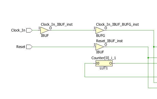
In dem angehängten Bild (Bild 1) ist die Eingangsstufe für den Takt 
gezeigt. Warum werden da zwei Buffer verwendet (wovon einer invertiert)?

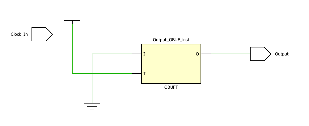
Wenn ich mir jetzt ein Top-Design dafür erstelle und es synthetisiere 
und mir anschließend die Schaltung ausgebe, dann optimiert die Toolchain 
die Schaltung weg (siehe Bild 2):
1
----------------------------------------------------------------------------------
2
-- Company: 
3
-- Engineer: 
4
-- 
5
-- Create Date:         10.02.2015 07:51:07
6
-- Design Name: 
7
-- Module Name:         Top - Top_Arch
8
-- Project Name: 
9
-- Target Devices: 
10
-- Tool Versions: 
11
-- Description: 
12
-- 
13
-- Dependencies: 
14
-- 
15
-- Revision:-- Revision 0.01 - File Created
16
-- Additional Comments:
17
-- 
18
----------------------------------------------------------------------------------
19

20
library IEEE;
21
use IEEE.STD_LOGIC_1164.ALL;
22
use IEEE.NUMERIC_STD.ALL;
23

24
entity Top is
25
    Port (  Output : out STD_LOGIC;
26
            Clock_In : in STD_LOGIC);
27
end Top;
28

29
architecture Top_Arch of Top is
30

31
    signal Compare      : std_logic;
32
    signal Overflow     : std_logic;
33
    signal PWM          : std_logic;
34
    signal Clock_Out    : std_logic;
35

36
    component Timer is
37
        Generic (   Width : integer := 8 );
38
        Port (      Clock_In : in STD_LOGIC;
39
                    Reset : in STD_LOGIC;
40
                    Prescaler : in STD_LOGIC_VECTOR(2 downto 0);
41
                    Preload : in STD_LOGIC_VECTOR(Width - 1 downto 0);
42
                    Capture : in STD_LOGIC_VECTOR(Width - 1 downto 0);
43
                    PWM_Enable : in STD_LOGIC;
44
                    PWM_Inv : in STD_LOGIC;
45
                    Compare : out STD_LOGIC;
46
                    Overflow : out STD_LOGIC;
47
                    PWM : out STD_LOGIC;
48
                    Clock_Out : out STD_LOGIC); 
49
    end component;
50
    
51
begin
52

53
    -- Device Instantiation
54
    TT0: Timer port map(Clock_In, '0', "000", "00000000", "00000000", '0', '0', Compare, Overflow, PWM, Clock_Out);
55

56
end Top_Arch;

Warum tut er das?
Danke für die Hilfe :)
Angehängte Dateien:
#4026695
Lesenswert?

In der Synthese wird alles weggekürzt was nicht notwendig ist.

Dein Topdesign hat nur das Ausgabesignal Output.
Dieses Signal wird nie zugewiesen. Der restliche Teil deiner Architektur 
verlässt das TopDesign nie. Deshalb kann es einfach weggekürzt werden.

Du musst dafür sorgen, dass das Outputsignal im Topdesign verändert 
wird.
Dann wird alles, von dem das Signal abhängt nicht entfernt.
1
 TT0: Timer port map(Clock_In, '0', "000", "00000000", "00000000", '0', '0', Compare, Overflow, PWM, Output);

Antwort schreiben

Bitte melde dich an, um einen Beitrag zu schreiben.

oder

Mit Google-Account einloggen

Die Registrierung ist kostenlos und dauert nur eine Minute.

Jetzt registrieren