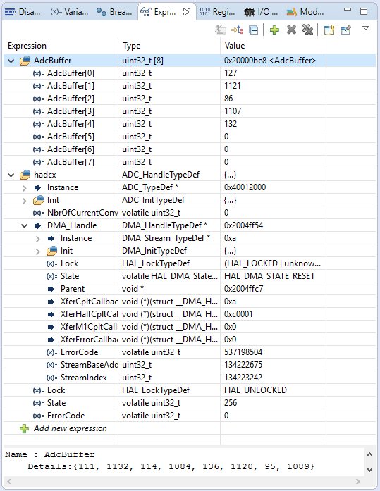
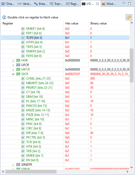
Liebe Mikrocontroller Gemeinde,

auf dem STM32F746 Discovery habe ich leider ein Problem mit dem DMA
Interrupt. Der DMA ist an den ADC angebunden, welcher etwa im
Sekundentakt von TIM2 getriggert wird. Das ganze läuft einwandfrei
solange der Buffer nicht (halb)voll ist und somit der DMA Interrupt
(DMA2_Stream0_IRQHandler) ausgelöst wird. Dann bleibt der Controller
nämlich in dieser IRQ hängen, denn die HAL Funktion (HAL_DMA_IRQHandler)
erkennt den Interrupt nicht. Setze ich das Flag TCIF0 (bzw. HTIF0 für
Half-Transfer) mittels CTCIF0 (bzw. CHTIF0) im Debugger manuell zurück,
läuft alles wie gewollt weiter bis zum nächsten Interrupt.

Der STM32 läuft mit SYSCLK = 216 MHz und APB2 = 108 MHz. Meine
Funktionen lauten wie folgt (teilweise habe ich die (Define)Werte der
Übersicht gleich eingesetzt):

Timer2 als Trigger für ADC1:
1 | TIM_HandleTypeDef htim; |
2 | |
3 | /**
|
4 | * @brief TIM configuration
|
5 | * @param Period: value to be loaded into the active
|
6 | * @param Prescaler: value used to divide the TIM clock
|
7 | * @retval None
|
8 | */
|
9 | void TIM_Config(uint32_t Period, uint32_t Prescaler) |
10 | {
|
11 | TIM_MasterConfigTypeDef TIM_MasterConfigStruct; |
12 | |
13 | /*##-1- Configure the TMR peripheral #######################################*/
|
14 | htim.Instance = TIM2; |
15 | |
16 | htim.Init.Period = Period; |
17 | htim.Init.Prescaler = Prescaler; |
18 | htim.Init.ClockDivision = TIM_CLOCKDIVISION_DIV4; |
19 | htim.Init.CounterMode = TIM_COUNTERMODE_UP; |
20 | htim.Init.RepetitionCounter = 0x0; |
21 | |
22 | if (HAL_TIM_Base_Init(&htim) != HAL_OK) |
23 | {
|
24 | /* Timer initialization Error */
|
25 | Error_Handler(); |
26 | }
|
27 | |
28 | /*##-2- Timer TRGO selection (p. 15, AN4676) ###############################*/
|
29 | TIM_MasterConfigStruct.MasterOutputTrigger = TIM_TRGO_UPDATE; |
30 | TIM_MasterConfigStruct.MasterSlaveMode = TIM_MASTERSLAVEMODE_DISABLE; |
31 | |
32 | if (HAL_TIMEx_MasterConfigSynchronization(&htim, &TIM_MasterConfigStruct) != HAL_OK) |
33 | {
|
34 | /* Timer TRGO selection Error */
|
35 | Error_Handler(); |
36 | }
|
37 | }
|
38 | |
39 | /**
|
40 | * @brief Start TMR
|
41 | * @param None
|
42 | * @retval None
|
43 | */
|
44 | void TMR_StartInterrupt(void) |
45 | {
|
46 | /*##-1- Enabled the DAC clock ##############################################*/
|
47 | __HAL_RCC_DAC_CLK_ENABLE(); /* @todo trouble issue: http://t i n y u r l.com/z9pflvk */ |
48 | |
49 | /*##-2- TIM counter enable #################################################*/
|
50 | if (HAL_TIM_Base_Start_IT(&htim) != HAL_OK) |
51 | {
|
52 | /* Starting Error */
|
53 | Error_Handler(); |
54 | }
|
55 | }
|
ADC1 Channel 0 an PA0:
1 | ADC_HandleTypeDef hadcx; |
2 | |
3 | uint32_t AdcBuffer[8]; |
4 | |
5 | /**
|
6 | * @brief Configure the ADC.
|
7 | * @param None
|
8 | * @retval None
|
9 | */
|
10 | void ADC_Config(void) |
11 | {
|
12 | ADC_ChannelConfTypeDef ADC_ChannelConfStruct; |
13 | |
14 | /*##-1- Configure the ADCx peripheral ######################################*/
|
15 | hadcx.Instance = ADC1; |
16 | |
17 | hadcx.Init.ClockPrescaler = ADC_CLOCKPRESCALER_PCLK_DIV4; |
18 | hadcx.Init.Resolution = ADC_RESOLUTION_12B; |
19 | hadcx.Init.ScanConvMode = DISABLE; |
20 | hadcx.Init.ContinuousConvMode = DISABLE; |
21 | hadcx.Init.DiscontinuousConvMode = DISABLE; |
22 | hadcx.Init.NbrOfDiscConversion = 0; |
23 | hadcx.Init.ExternalTrigConvEdge = ADC_EXTERNALTRIGCONVEDGE_RISING; |
24 | hadcx.Init.ExternalTrigConv = ADC_EXTERNALTRIGCONV_T2_TRGO; |
25 | hadcx.Init.DataAlign = ADC_DATAALIGN_RIGHT; |
26 | hadcx.Init.NbrOfConversion = 1; |
27 | hadcx.Init.DMAContinuousRequests = ENABLE; |
28 | hadcx.Init.EOCSelection = ADC_EOC_SEQ_CONV; |
29 | |
30 | if (HAL_ADC_Init(&hadcx) != HAL_OK) |
31 | {
|
32 | /* Initialization Error */
|
33 | Error_Handler(); |
34 | }
|
35 | |
36 | /*##-2- Configure ADCx regular channel ######################################*/
|
37 | ADC_ChannelConfStruct.Channel = ADC_CHANNEL_0; |
38 | ADC_ChannelConfStruct.Rank = 1; |
39 | ADC_ChannelConfStruct.SamplingTime = ADC_SAMPLETIME_480CYCLES; |
40 | ADC_ChannelConfStruct.Offset = 0; |
41 | |
42 | if (HAL_ADC_ConfigChannel(&hadcx, &ADC_ChannelConfStruct) != HAL_OK) |
43 | {
|
44 | /* Channel Configuration Error */
|
45 | Error_Handler(); |
46 | }
|
47 | }
|
48 | |
49 | |
50 | /**
|
51 | * @brief Start ADC and write values with DMA
|
52 | * @param None
|
53 | * @retval None
|
54 | */
|
55 | void ADC_StartDma(void) |
56 | {
|
57 | /*##-1- Start DMA conversion process #######################################*/
|
58 | if(HAL_ADC_Start_DMA(&hadcx, (uint32_t *)&AdcBuffer, 8) != HAL_OK) |
59 | {
|
60 | /* Start Conversation Error */
|
61 | Error_Handler(); |
62 | }
|
63 | |
64 | /* Disable all IRQ except Transfer Complete */
|
65 | // hadcx.DMA_Handle->Instance->CR &= ((uint32_t)~(DMA_IT_HT | DMA_IT_TE | DMA_IT_DME));
|
66 | }
|
Die Init des DMA sowie des GPIO und die TMR Clock habe ich in der HAL
MSP module integriert.
1 | /**
|
2 | * @brief ADC MSP Initialization
|
3 | * This function configures the hardware resources used in this example:
|
4 | * - Peripheral's clock enable
|
5 | * - Peripheral's GPIO Configuration
|
6 | * @param hadc: ADC handle pointer
|
7 | * @retval None
|
8 | */
|
9 | void HAL_ADC_MspInit(ADC_HandleTypeDef* hadc) |
10 | {
|
11 | GPIO_InitTypeDef GPIO_InitStruct; |
12 | DMA_HandleTypeDef hdma_adc; |
13 | |
14 | /*##-1- Enable peripherals and GPIO Clocks #################################*/
|
15 | /* Enable GPIO clock */
|
16 | __HAL_RCC_GPIOA_CLK_ENABLE(); |
17 | /* ADCx Periph clock enable */
|
18 | __HAL_RCC_ADC1_CLK_ENABLE(); |
19 | /* Enable DMA clock */
|
20 | __HAL_RCC_DMA2_CLK_ENABLE(); |
21 | |
22 | /*##-2- Configure peripheral GPIO ##########################################*/
|
23 | /* ADC Channel GPIO pin configuration */
|
24 | GPIO_InitStruct.Pin = GPIO_PIN_0; |
25 | GPIO_InitStruct.Mode = GPIO_MODE_ANALOG; |
26 | GPIO_InitStruct.Pull = GPIO_NOPULL; |
27 | HAL_GPIO_Init(GPIOA, &GPIO_InitStruct); |
28 | |
29 | /*##-3- Configure the DMA streams ##########################################*/
|
30 | /* Set the parameters to be configured */
|
31 | hdma_adc.Instance = DMA2_Stream0; |
32 | |
33 | hdma_adc.Init.Channel = DMA_CHANNEL_0; |
34 | hdma_adc.Init.Direction = DMA_PERIPH_TO_MEMORY; |
35 | hdma_adc.Init.PeriphInc = DMA_PINC_DISABLE; |
36 | hdma_adc.Init.MemInc = DMA_MINC_ENABLE; |
37 | hdma_adc.Init.PeriphDataAlignment = DMA_PDATAALIGN_WORD; |
38 | hdma_adc.Init.MemDataAlignment = DMA_MDATAALIGN_WORD; |
39 | hdma_adc.Init.Mode = DMA_CIRCULAR; |
40 | hdma_adc.Init.Priority = DMA_PRIORITY_HIGH; |
41 | hdma_adc.Init.FIFOMode = DMA_FIFOMODE_DISABLE; |
42 | hdma_adc.Init.FIFOThreshold = DMA_FIFO_THRESHOLD_HALFFULL; |
43 | hdma_adc.Init.MemBurst = DMA_MBURST_SINGLE; |
44 | hdma_adc.Init.PeriphBurst = DMA_PBURST_SINGLE; |
45 | |
46 | if(HAL_DMA_Init(&hdma_adc) != HAL_OK) |
47 | {
|
48 | /* DMA Init Error */
|
49 | Error_Handler(); |
50 | }
|
51 | |
52 | /* Associate the initialized DMA handle to the ADC handle */
|
53 | __HAL_LINKDMA(hadc, DMA_Handle, hdma_adc); |
54 | |
55 | /*##-4- Configure the NVIC for DMA #########################################*/
|
56 | /* NVIC configuration for DMA transfer complete interrupt */
|
57 | HAL_NVIC_SetPriority(DMA2_Stream0_IRQn, 0, 0); |
58 | HAL_NVIC_EnableIRQ(DMA2_Stream0_IRQn); |
59 | }
|
60 | |
61 | /**
|
62 | * @brief TIM MSP Initialization
|
63 | * This function configures the hardware resources used in this example:
|
64 | * - Peripheral's clock enable
|
65 | * - Peripheral's GPIO Configuration
|
66 | * @param htim: TIM handle pointer
|
67 | * @retval None
|
68 | */
|
69 | void HAL_TIM_Base_MspInit(TIM_HandleTypeDef *htim) |
70 | {
|
71 | /*##-1- Enable timer Clock #################################################*/
|
72 | __HAL_RCC_TIM2_CLK_ENABLE(); |
73 | |
74 | /*##-2- Configure the NVIC for TIMx ########################################*/
|
75 | /* Set the TIMx priority */
|
76 | HAL_NVIC_SetPriority(TIM2_IRQn, 2, 0); |
77 | HAL_NVIC_EnableIRQ(TIM2_IRQn); |
78 | }
|
Die Interrupt Handlers sehen wie folgt aus:
1 | /**
|
2 | * @brief This function handles DMA interrupt request.
|
3 | * @param None
|
4 | * @retval None
|
5 | */
|
6 | void DMA2_Stream0_IRQHandler(void) |
7 | {
|
8 | HAL_DMA_IRQHandler(hadcx.DMA_Handle); |
9 | }
|
10 | |
11 | /**
|
12 | * @brief This function handles TIM interrupt request.
|
13 | * @param None
|
14 | * @retval None
|
15 | */
|
16 | void TIM2_IRQHandler(void) |
17 | {
|
18 | HAL_TIM_IRQHandler(&htim); |
19 | }
|
Die relevanten Ausschnitte der main.c lauten:
1 | /**
|
2 | * @brief Main program.
|
3 | * @param None
|
4 | * @retval None
|
5 | */
|
6 | int main(void) |
7 | {
|
8 | /* Configure the MPU attributes as Write Through */
|
9 | // MPU_Config();
|
10 | |
11 | /* Enable the CPU Cache */
|
12 | CPU_CACHE_Enable(); |
13 | |
14 | /* STM32F7xx HAL library initialization:
|
15 | - Configure the Flash prefetch
|
16 | - Systick timer is configured by default as source of time base, but user
|
17 | can eventually implement his proper time base source (a general purpose
|
18 | timer for example or other time source), keeping in mind that Time base
|
19 | duration should be kept 1ms since PPP_TIMEOUT_VALUEs are defined and
|
20 | handled in milliseconds basis.
|
21 | - Set NVIC Group Priority to 4
|
22 | - Low Level Initialization
|
23 | */
|
24 | HAL_Init(); |
25 | |
26 | /* Configure the system clock to 216 MHz */
|
27 | SystemClock_Config(); |
28 | |
29 | /* Configure LED1 */
|
30 | BSP_LED_Init(LED1); |
31 | |
32 | /* Configure the LCD peripheral */
|
33 | LCD_Config(); |
34 | |
35 | /* Configure the ADC peripheral */
|
36 | TIM_Config(1999, 49999); |
37 | |
38 | /* Configure the ADC peripheral */
|
39 | ADC_Config(); |
40 | |
41 | /* Start ADC with TMR based conversion process and enable DMA */
|
42 | ADC_StartDma(); |
43 | |
44 | /* Start TMR */
|
45 | TMR_StartInterrupt(); |
46 | |
47 | /* Infinite loop */
|
48 | while (1) |
49 | {
|
50 | /* Display the TMR value */
|
51 | LCD_ShowValue(htim.Instance->CNT, 0, "TMR"); |
52 | |
53 | /* Display the ADC value */
|
54 | LCD_ShowValue(AdcBuffer[0], 2, "ADC0"); |
55 | LCD_ShowValue(AdcBuffer[1], 3, "ADC1"); |
56 | LCD_ShowValue(AdcBuffer[2], 4, "ADC2"); |
57 | LCD_ShowValue(AdcBuffer[3], 5, "ADC3"); |
58 | LCD_ShowValue(AdcBuffer[4], 6, "ADC4"); |
59 | LCD_ShowValue(AdcBuffer[5], 7, "ADC5"); |
60 | LCD_ShowValue(AdcBuffer[6], 8, "ADC6"); |
61 | LCD_ShowValue(AdcBuffer[7], 9, "ADC7"); |
62 | |
63 | LCD_ShowValue(AdcValue, 11, "VAL"); |
64 | }
|
65 | }
|
66 | |
67 | /**
|
68 | * @brief Period elapsed callback in non blocking mode
|
69 | * @param htim : TIM handle
|
70 | * @retval None
|
71 | */
|
72 | void HAL_TIM_PeriodElapsedCallback(TIM_HandleTypeDef *htim) |
73 | {
|
74 | /* Increase ADC cycle counter */
|
75 | AdcCycleNumber += 1; |
76 | LCD_ShowValue(AdcCycleNumber, 1, "CYC"); |
77 | }
|
78 | |
79 | /**
|
80 | * @brief Conversion complete callback in non blocking mode
|
81 | * @param hadc: hadc handle
|
82 | * @retval None
|
83 | */
|
84 | void HAL_ADC_ConvCpltCallback(ADC_HandleTypeDef* hadc) |
85 | {
|
86 | uint32_t DmaOffsetBefore = 0, DmaOffsetAfter = 0; |
87 | |
88 | /* DMA timings by saving the value of the NDTR (remaining amount of values) */
|
89 | DmaOffsetBefore = ADC_BUFFER_SIZE - ADCxyz_DMA_STREAM->NDTR; |
90 | |
91 | /* Do something */
|
92 | |
93 | /* DMA timings, BUFFER_SIZE can be adjusted, otherwise use HAL_ADC_ConvHalfCpltCallback() */
|
94 | DmaOffsetAfter = ADC_BUFFER_SIZE - ADCxyz_DMA_STREAM->NDTR; |
95 | |
96 | LCD_ShowValue(DmaOffsetBefore-DmaOffsetAfter, 13, "DMA"); |
97 | }
|
98 | |
99 | /**
|
100 | * @brief Regular conversion half DMA transfer callback in non blocking mode
|
101 | * @param hadc: pointer to a ADC_HandleTypeDef structure that contains
|
102 | * the configuration information for the specified ADC.
|
103 | * @retval None
|
104 | */
|
105 | void HAL_ADC_ConvHalfCpltCallback(ADC_HandleTypeDef* hadc) |
106 | {
|
107 | uint32_t DmaOffsetBefore = 0, DmaOffsetAfter = 0; |
108 | |
109 | /* DMA timings by saving the value of the NDTR (remaining amount of values) */
|
110 | DmaOffsetBefore = ADC_BUFFER_SIZE - ADCxyz_DMA_STREAM->NDTR; |
111 | |
112 | /* Do something */
|
113 | |
114 | /* DMA timings, BUFFER_SIZE can be adjusted, otherwise use HAL_ADC_ConvHalfCpltCallback() */
|
115 | DmaOffsetAfter = ADC_BUFFER_SIZE - ADCxyz_DMA_STREAM->NDTR; |
116 | |
117 | LCD_ShowValue(DmaOffsetBefore-DmaOffsetAfter, 13, "DMA"); |
118 | }
|
Im ST-Forum (https://my.st.com/public/STe2ecommunities/mcu/Lists/cortex_mx_stm32/Flat.aspx?RootFolder=https%3a%2f%2fmy%2est%2ecom%2fpublic%2fSTe2ecommunities%2fmcu%2fLists%2fcortex%5fmx%5fstm32%2fHAL%20DMA%20ADC%20Interrupt%20stuck%20in%20IRQ%20Handler&FolderCTID=0x01200200770978C69A1141439FE559EB459D7580009C4E14902C3CDE46A77F0FFD06506F5B¤tviews=2329) habe ich einen ähnlichen Beitrag gefunden, leider wird hierzu keine Lösung angeboten. Die genannten Vorschläge haben bei mir leider nicht geholfen... Ich bin über jeden Ratschlag dankbar, ansonsten helfen die Init Funktionen vielleicht dem nächsten, ansich laufen diese! Vielen Dank im Voraus, Grüße MFH PS: Im Anhang noch ein Bild während des Half-Transfer Interrupt (Breakpoint in DMA2_Stream0_IRQHandler), der Buffer ist also nur halb voll und wird im Hintergrund fleißig weiter befüllt. Außerdem das entsprechende Register des DMA2 und die gesetzen Interrupt Flags (TCIF0 wurde durch die Aktuallisierung gesetzt).