Gast
#5102723
Hier auf http://theradioboard.com/rb/viewtopic.php?f=4&t=7770 habe ich
einen Thread gestartet mit dem Namen "BJT square-law detectors versus
biased full-wave diode detectors". Hier folgt meinen Beitrag in der
Startpost dieses Threades auf Englischen:

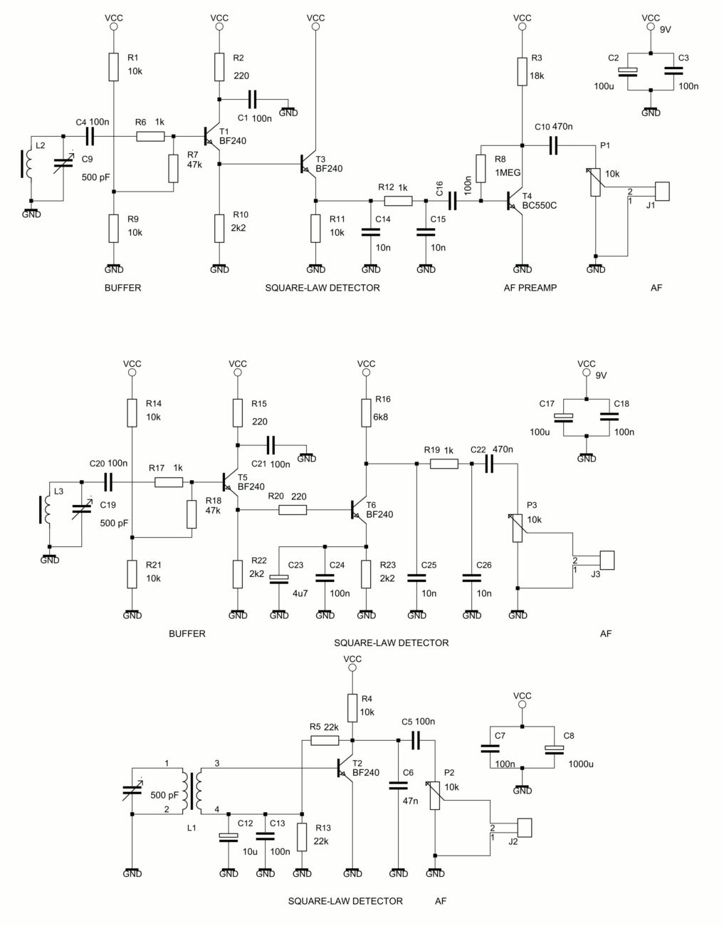
"I have done some experiments with BJT square-law detectors and a biased
diode detector with an RF amplifier ahead of the diode detector stage. I
used an emitter-coupled Q-multiplier for receiving weak signals, in the
circuit diagrams below the Q-Multiplier has been omitted.

I have noticed that a BJT square-law detector suffers from AF noise
which is generated inside the BJT square-law detector stage itself. When
the coupling capacitor from the tank circuit to the BJT detector stage
has a small value, there is excessive AF noise at the AF output of the
BJT detector and detector efficiency is lost. Using a large coupling
capacitor from the tank circuit to the detector stage gives much less AF
noise at the AF output of a BJT square-law detector, but then this stage
is susceptible for picking up mains hum when a medium wave ferrite bar
antenna is used as a tank circuit coil. The statement that a BJT
square-law detector should be very sensitive, seems not to be true. What
must be done to avoid excessive AF noise at the output of any BJT
square-law detector?

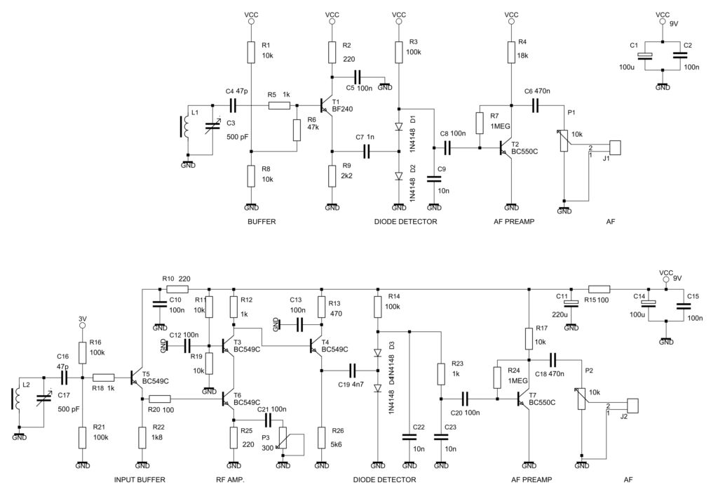
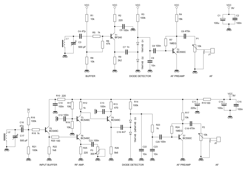
A biased full-wave diode detector with an RF amplifier ahead of it (see
lowermost circuit diagram) gives almost no AF noise at the diode
detector output, because generated AF noise isn't transferred from the
RF amplifier stage to the diode detector stage at all due to the small
coupling cap between the amplifier stage and the diode detector. And a
diode detector with an RF amplifier ahead of it is very sensitive for
receiving AM signals below oscillating threshold of a Q-Multiplier
stage, also very important when using small antennas like a whip antenna
on Shortwave and a ferrite loop stick on Medium Wave.

To have a sensitive detection of AM signals with a diode detector two
things are very important:

Firstly, the diode detector has to be driven from a low-Z source for a
good impedance matching between the RF amplifier stage and the diode
detector stage , hence an emitter follower is inserted between the RF
amplifier stage and the diode detector stage. Secondly the diodes of the
diode detector has to be biased with a small bias current, especially
when small-signal silicon diodes are used."
Angehängte Dateien:
-
 BJT-Detectors.gif
(88 KB)
BJT-Detectors.gif
(88 KB)
-
 DiodeDetectors.gif
(65 KB)
DiodeDetectors.gif
(65 KB)