von
Dirk (Gast)
22.09.2006 18:05
Hallo, ich möchte in einer FOR LOOP Schleife per Index die Inputs des
Moduls abfragen, bloss wie lege ich in der Enity die Inputs als Array
an?
1 library IEEE ;
2 use IEEE . STD_LOGIC_1164 . ALL ;
3 use IEEE . STD_LOGIC_ARITH . ALL ;
4 use IEEE . STD_LOGIC_UNSIGNED . ALL ;
5
6 ---- Uncomment the following library declaration if instantiating
7 ---- any Xilinx primitives in this code.
8 --library UNISIM;
9 --use UNISIM.VComponents.all;
10
11 entity async_pwm is
12 PORT ( CLK : in std_logic ;
13 RST : in std_logic ;
14 channel : out std_logic_vector ( 7 downto 0 );
15 value0 : in std_logic_vector ( 7 downto 0 );
16 value1 : in std_logic_vector ( 7 downto 0 );
17 value2 : in std_logic_vector ( 7 downto 0 );
18 value3 : in std_logic_vector ( 7 downto 0 );
19 value4 : in std_logic_vector ( 7 downto 0 );
20 value5 : in std_logic_vector ( 7 downto 0 );
21 value6 : in std_logic_vector ( 7 downto 0 );
22 value7 : in std_logic_vector ( 7 downto 0 )
23
24
25 );
26
27 end async_pwm ;
28
29 architecture Behavioral of async_pwm is
30
31 type arrayfield is array ( 0 to 7 ) of std_logic_vector ( 7 downto 0 );
32
33 signal value_help : arrayfield ;
34 signal timer_cnt : std_logic_vector ( 7 downto 0 );
35 signal channel_int : std_logic_vector ( 7 downto 0 );
36 begin
37
38
39 process ( clk )
40 begin
41 if rising_edge ( clk ) then
42 if rst = '1' then
43 channel_int <= "00000000" ;
44 FOR index IN 0 TO 7 LOOP
45 value_help ( index ) <= "00000000" ;
46 END LOOP ;
47 else
48 FOR index IN 0 TO 7 LOOP
49 value_help ( index ) <= value_help ( index ) + 1 ;
50 if value_help ( index ) = "11111111" then
51 channel_int ( index ) <= '1' ;
52 end if ;
53
54 if value_help ( index ) = value0 and value0 > 0 then -- value0 - value7
55 als index ( value ( index )
56 channel_int ( index ) <= '0' ;
57 end if ;
58 END LOOP ;
59
60 end if ;
61 end if ;
62 end process ;
63
64 channel <= channel_int ;
65
66 end Behavioral ;
Oder funktioniert das in VHDL nicht?

Gruß,
Dirk
von
tobias (Gast)
22.09.2006 18:15
Du legst einfach deine Typedefinition in ein Package ab:
type arrayfield is array (0 to 7) of  std_logic_vector(7 downto 0);
Includierst das Package.

Danach kannst du ein Signal dieses Typs einfach als Ein- oder Ausgang
in
deine Entity Mappen.
von
Dirk (Gast)
22.09.2006 19:18
Hattest du ein Beispiel? Ich kann Dir leider nicht ganz folgen.
von
tobias (Gast)
22.09.2006 21:45
Schau dir einfach die beiden Dateien an. Eine Datei enthält eine Reihe
von Datentypen, in der anderen Datei werden diese Datentypen als In und
Out in der Entity benutzt.
Du kannst jeden Datentyp den du dir selbst definiert hast als In und
Out- Port benutzen. Es spielt keine Rolle um was für einen Datentyp es
sich handelt ! Wenn du nicht weiter weisst, dann präzisiere doch deine
Fragestellung. Vielleicht habe ich nicht richtig verstanden was du
meinst.
von
Dirk (Gast)
23.09.2006 21:47
Hallo, ich hab mir jetzt das Package definiert.
1 library IEEE ;
2 use IEEE . STD_LOGIC_1164 . all ;
3
4 package value is
5 type arrayfield2 is array ( 0 to 7 ) of std_logic_vector ( 7 downto 0 );
6 end value ;
In meiner Behav. Beschreibung habe ich das Package in der Entity als
Input deklariert. Die Synthese generiert mir auch meine
Logikbeschreibung, aber Modelsim bringt mir beim Compelieren Fehler.
1 library IEEE ;
2 use IEEE . STD_LOGIC_1164 . ALL ;
3 use IEEE . STD_LOGIC_ARITH . ALL ;
4 use IEEE . STD_LOGIC_UNSIGNED . ALL ;
5
6 ---- Uncomment the following library declaration if instantiating
7 ---- any Xilinx primitives in this code.
8 --library UNISIM;
9 --use UNISIM.VComponents.all;
10 use work . value . ALL ;
11
12 entity async_pwm is
13 PORT ( CLK : in std_logic ;
14 RST : in std_logic ;
15 EN : in std_logic ;
16 channel : out std_logic_vector ( 7 downto 0 );
17 value : in arrayfield2
18 );
19
20 end async_pwm ;
21
22 architecture Behavioral of async_pwm is
23
24 type arrayfield is array ( 0 to 7 ) of std_logic_vector ( 7 downto 0 );
25
26 signal value_help : arrayfield ;
27 signal channel_int : std_logic_vector ( 7 downto 0 );
28 begin
29
30 process ( clk )
31 begin
32 if rising_edge ( clk ) then
33 if rst = '1' then
34 channel_int <= "00000000" ;
35 FOR index IN 0 TO 7 LOOP
36 value_help ( index ) <= "00000000" ;
37 END LOOP ;
38 else
39 if EN = '1' then
40 FOR index IN 0 TO 7 LOOP
41 value_help ( index ) <= value_help ( index ) + 1 ;
42 if value_help ( index ) = "11111111" then
43 channel_int ( index ) <= '0' ;
44 end if ;
45
46 if value_help ( index ) = value ( index ) and value ( index ) > 0 then
47 channel_int ( index ) <= '1' ;
48 end if ;
49 END LOOP ;
50 end if ;
51 end if ;
52 end if ;
53 end process ;
54
55 channel <= channel_int ;
56
57 end Behavioral ;
Die Fehlermedlungen von Modelsim:

# ** Error: tb_a2.vhw(41): (vcom-1136) Unknown identifier
"arrayfield2base".
# ** Error: tb_a2.vhw(49): (vcom-1136) Unknown identifier
"arrayfield2base".
# ** Error: tb_a2.vhw(49): String literal found where non-array type
(error) was expected.
# ** Error: tb_a2.vhw(109): String literal found where non-array type
(error) was expected.
# ** Error: tb_a2.vhw(113): String literal found where non-array type
(error) was expected.
# ** Error: tb_a2.vhw(133): VHDL Compiler exiting
# ** Error: F:/Mikrocontroller/modelsim6.1/win32xoem/vcom failed.

Kann mir jemand weiterhelfen?

Gruß,

Dirk
von
Dirk (Gast)
23.09.2006 22:07
Mir kommt es so vor als wenn das Package bzw. das Array falsch
deklariert ist und zwar nicht als 8 * 8 Bit Array.

Hier mein Testbenchfile, vielleicht hilft es weiter.
1 library IEEE ;
2 use IEEE . STD_LOGIC_1164 . ALL ;
3 use IEEE . STD_LOGIC_ARITH . ALL ;
4 use IEEE . STD_LOGIC_UNSIGNED . ALL ;
5 library work ;
6 use work . value . ALL ;
7 USE IEEE . STD_LOGIC_TEXTIO . ALL ;
8 USE STD . TEXTIO . ALL ;
9
10 ENTITY tb3_tb_0 IS
11 END tb3_tb_0 ;
12
13 ARCHITECTURE testbench_arch OF tb3_tb_0 IS
14 FILE RESULTS : TEXT OPEN WRITE_MODE IS "results.txt" ;
15
16 COMPONENT async_pwm
17 PORT (
18 CLK : In std_logic ;
19 RST : In std_logic ;
20 EN : In std_logic ;
21 channel : Out std_logic_vector ( 7 DownTo 0 );
22 value : In arrayfield2Base ( 0 To 7 )
23 );
24 END COMPONENT ;
25
26 SIGNAL CLK : std_logic : = '0' ;
27 SIGNAL RST : std_logic : = '0' ;
28 SIGNAL EN : std_logic : = '0' ;
29 SIGNAL channel : std_logic_vector ( 7 DownTo 0 ) : = "00000000" ;
30 SIGNAL value : arrayfield2Base ( 0 To 7 ) : = "00000000" ;
31
32 SHARED VARIABLE TX_ERROR : INTEGER : = 0 ;
33 SHARED VARIABLE TX_OUT : LINE ;
34
35 constant PERIOD : time : = 40 ns ;
36 constant DUTY_CYCLE : real : = 0 . 5 ;
37 constant OFFSET : time : = 0 ns ;
38
39 BEGIN
40 UUT : async_pwm
41 PORT MAP (
42 CLK => CLK ,
43 RST => RST ,
44 EN => EN ,
45 channel => channel ,
46 value => value
47 );
48
49 PROCESS -- clock process for CLK
50 BEGIN
51 WAIT for OFFSET ;
52 CLOCK_LOOP : LOOP
53 CLK <= '0' ;
54 WAIT FOR ( PERIOD - ( PERIOD * DUTY_CYCLE ));
55 CLK <= '1' ;
56 WAIT FOR ( PERIOD * DUTY_CYCLE );
57 END LOOP CLOCK_LOOP ;
58 END PROCESS ;
59
60 PROCESS
61 PROCEDURE CHECK_channel (
62 next_channel : std_logic_vector ( 7 DownTo 0 );
63 TX_TIME : INTEGER
64 ) IS
65 VARIABLE TX_STR : String ( 1 to 4096 );
66 VARIABLE TX_LOC : LINE ;
67 BEGIN
68 IF ( channel /= next_channel ) THEN
69 STD . TEXTIO . write ( TX_LOC , string ' ( "Error at
70 time=" ));
71 STD . TEXTIO . write ( TX_LOC , TX_TIME );
72 STD . TEXTIO . write ( TX_LOC , string ' ( "ns
73 channel=" ));
74 IEEE . STD_LOGIC_TEXTIO . write ( TX_LOC , channel );
75 STD . TEXTIO . write ( TX_LOC , string ' ( ", Expected =
76 " ));
77 IEEE . STD_LOGIC_TEXTIO . write ( TX_LOC , next_channel );
78 STD . TEXTIO . write ( TX_LOC , string ' ( " " ));
79 TX_STR ( TX_LOC . all 'range ) : = TX_LOC . all ;
80 STD . TEXTIO . writeline ( RESULTS , TX_LOC );
81 STD . TEXTIO . Deallocate ( TX_LOC );
82 ASSERT ( FALSE ) REPORT TX_STR SEVERITY ERROR ;
83 TX_ERROR : = TX_ERROR + 1 ;
84 END IF ;
85 END ;
86 BEGIN
87 -- ------------- Current Time: 3045ns
88 WAIT FOR 3045 ns ;
89 value <= "10000000" ;
90 -- -------------------------------------
91 -- ------------- Current Time: 3405ns
92 WAIT FOR 360 ns ;
93 value <= "11000000" ;
94 -- -------------------------------------
95 -- ------------- Current Time: 8965ns
96 WAIT FOR 5560 ns ;
97 value <= "01000000" ;
98 -- -------------------------------------
99 -- ------------- Current Time: 9005ns
100 WAIT FOR 40 ns ;
101 value <= "00000000" ;
102 -- -------------------------------------
103 WAIT FOR 91035 ns ;
104
105 IF ( TX_ERROR = 0 ) THEN
106 STD . TEXTIO . write ( TX_OUT , string ' ( "No errors or
107 warnings" ));
108 STD . TEXTIO . writeline ( RESULTS , TX_OUT );
109 ASSERT ( FALSE ) REPORT
110 "Simulation successful (not a failure). No
111 problems detected."
112 SEVERITY FAILURE ;
113 ELSE
114 STD . TEXTIO . write ( TX_OUT , TX_ERROR );
115 STD . TEXTIO . write ( TX_OUT ,
116 string ' ( " errors found in simulation" ));
117 STD . TEXTIO . writeline ( RESULTS , TX_OUT );
118 ASSERT ( FALSE ) REPORT "Errors found during
119 simulation"
120 SEVERITY FAILURE ;
121 END IF ;
122 END PROCESS ;
123
124 END testbench_arch ;
Dirk
von
T.M. (Gast)
23.09.2006 22:23
Deine Component Declaration in der Testbench stimmt doch gar nicht mit
der Entity des Designs überein. Oder was ist arrayfield2Base für ein
Typ?
von
Dirk (Gast)
23.09.2006 22:27
Hallo, das arrayfield2Base sollte eigentlich das 8 * 8 Bit Array
darstellen. Das Testbench ist mit dem ISE Testbench Waveform View
erstellt.
1 library IEEE ;
2 use IEEE . STD_LOGIC_1164 . all ;
3 package value is type arrayfield2 is array ( 0 to 7 ) of
4 std_logic_vector ( 7 downto 0 );
5 end value ;
Ist es ein Programmfehler vom testbench waveform viever?

Wie muesste es den richtig sein?
von
T.M. (Gast)
23.09.2006 22:33
Das die Fehler zuerst bei der Component Instanziierung auftreten, deutet
zumindestens darauf hin, dass an den Ports was nicht stimmt. Das
Design-file hat er wohl anstandslos kompiliert, also stimmt auch das
Package. Da haut meiner Meinung was mit der Component Declaration nicht
hin.

Mach in der Testbench mal:
1 COMPONENT async_pwm
2 PORT (
3 CLK : In std_logic ;
4 RST : In std_logic ;
5 EN : In std_logic ;
6 channel : Out std_logic_vector ( 7 DownTo 0 );
7 value : In arrayfield2
8 );
9 END COMPONENT ;
T.M.
von
tobias (Gast)
23.09.2006 22:34
Hmm, ich habe deinen Sourcecode mit der Ise erfolgreich synthetisiert.
Modelsim hatte auch keine Probleme beim kompilieren der Dateien. Was
ist den "tb_a2.vhw" für eine Datei. Ich denke, dass das
Problem eher an deiner Testbench liegt. Ich vermute, dass du diese
automatisch oder grafisch erzeugt hast, und dort Datentypen verwendet
werden die nicht bekanntgegeben wurden. Aus der Ferne lässt sich dieses
aber schlecht beurteilen. Evtl. schreibst du die Testbench neu nach der
klassischen Methode als VHDL -Datei.
Gruß tobias
von
tobias (Gast)
23.09.2006 22:35
ups, da war jemand schneller
von
Dirk (Gast)
23.09.2006 22:42
Hallo, @tobias du hast recht das Testbench ist grafisch erzeugt. Hm, bis
jetzt hab ich eigentlich alles immer nur über die Grafikoberfläche
erstellt, deshalb wird es sehr schwierig fuer mich das Testbench
zuschreiben.

Das grafische Testbenchfile zum Project Adden klappt leider auch nicht
dann bekomme ich immer noch die Fehlermeldungen.

Gruß,
Dirk
von
Dirk (Gast)
23.09.2006 23:02
Vielleicht ist jemand von euch beiden so nett und kann mir nochmal beim
Testbench unter die Arme greifen.
1 LIBRARY ieee ;
2 USE ieee . std_logic_1164 . ALL ;
3 USE ieee . std_logic_unsigned . all ;
4 USE ieee . numeric_std . ALL ;
5
6 ENTITY tb4_vhd IS
7 END tb4_vhd ;
8
9 ARCHITECTURE behavior OF tb4_vhd IS
10
11 -- Component Declaration for the Unit Under Test (UUT)
12 COMPONENT async_pwm
13 PORT (
14 CLK : IN std_logic ;
15 RST : IN std_logic ;
16 EN : IN std_logic ;
17 value : IN std_logic_vector ( 0 to 7 );
18 channel : OUT std_logic_vector ( 7 downto 0 )
19 );
20 END COMPONENT ;
21
22 --Inputs
23 SIGNAL CLK : std_logic : = '0' ;
24 SIGNAL RST : std_logic : = '0' ;
25 SIGNAL EN : std_logic : = '0' ;
26 SIGNAL value : std_logic_vector ( 0 to 7 ) : = ( others => '0' );
27
28 --Outputs
29 SIGNAL channel : std_logic_vector ( 7 downto 0 );
30
31
32 constant PERIOD : time : = 40 ns ;
33 constant DUTY_CYCLE : real : = 0 . 5 ;
34 constant OFFSET : time : = 0 ns ;
35
36
37 BEGIN
38
39 -- Instantiate the Unit Under Test (UUT)
40 uut : async_pwm PORT MAP (
41 CLK => CLK ,
42 RST => RST ,
43 EN => EN ,
44 channel => channel ,
45 value => value
46 );
47
48 PROCESS -- clock process for CLK
49 BEGIN
50 WAIT for OFFSET ;
51 CLOCK_LOOP : LOOP
52 CLK <= '0' ;
53 WAIT FOR ( PERIOD - ( PERIOD * DUTY_CYCLE ));
54 CLK <= '1' ;
55 WAIT FOR ( PERIOD * DUTY_CYCLE );
56 END LOOP CLOCK_LOOP ;
57 END PROCESS ;
58
59
60 tb : PROCESS
61 BEGIN
62
63 -- Wait 100 ns for global reset to finish
64 wait for 100 ns ;
65 rst <= '1' ;
66 wait for 100 ns ;
67 rst <= '0' ;
68 value ( 0 ) <= "00001111" ;
69 wait for 10 ms ; -- will wait forever
70 END PROCESS ;
71
72 END ;
Ich bekomme beim starten des Testbench in Modelsim immer noch
Fehlermeldungen. Ich haette lieber bei der alten Methode bleiben sollen
und ohne For Schleifen arbeiten sollen.

Fehlermeldungen:
# ** Error: tb4.vhd(96): Incompatible types for signal assignment.
# ** Error: tb4.vhd(100): VHDL Compiler exiting
von
Dirk (Gast)
23.09.2006 23:08
Ich hab es geschafft. Vielen Dank und damit es anderen auch weiterhilft
hier das TB.
1 LIBRARY ieee ;
2 USE ieee . std_logic_1164 . ALL ;
3 USE ieee . std_logic_unsigned . all ;
4 USE ieee . numeric_std . ALL ;
5 use work . value . ALL ;
6
7 ENTITY tb4_vhd IS
8 END tb4_vhd ;
9
10 ARCHITECTURE behavior OF tb4_vhd IS
11
12 -- Component Declaration for the Unit Under Test (UUT)
13 COMPONENT async_pwm
14 PORT (
15 CLK : IN std_logic ;
16 RST : IN std_logic ;
17 EN : IN std_logic ;
18 value : IN arrayfield2 ;
19 channel : OUT std_logic_vector ( 7 downto 0 )
20 );
21 END COMPONENT ;
22
23 --Inputs
24 SIGNAL CLK : std_logic : = '0' ;
25 SIGNAL RST : std_logic : = '0' ;
26 SIGNAL EN : std_logic : = '0' ;
27 SIGNAL value : arrayfield2 ;
28
29 --Outputs
30 SIGNAL channel : std_logic_vector ( 7 downto 0 );
31
32
33 constant PERIOD : time : = 40 ns ;
34 constant DUTY_CYCLE : real : = 0 . 5 ;
35 constant OFFSET : time : = 0 ns ;
36
37
38 BEGIN
39
40 -- Instantiate the Unit Under Test (UUT)
41 uut : async_pwm PORT MAP (
42 CLK => CLK ,
43 RST => RST ,
44 EN => EN ,
45 channel => channel ,
46 value => value
47 );
48
49 PROCESS -- clock process for CLK
50 BEGIN
51 WAIT for OFFSET ;
52 CLOCK_LOOP : LOOP
53 CLK <= '0' ;
54 WAIT FOR ( PERIOD - ( PERIOD * DUTY_CYCLE ));
55 CLK <= '1' ;
56 WAIT FOR ( PERIOD * DUTY_CYCLE );
57 END LOOP CLOCK_LOOP ;
58 END PROCESS ;
59
60
61 tb : PROCESS
62 BEGIN
63
64 -- Wait 100 ns for global reset to finish
65 wait for 100 ns ;
66 rst <= '1' ;
67 wait for 100 ns ;
68 rst <= '0' ;
69 value ( 0 ) <= "00001111" ;
70 wait for 10 ms ; -- will wait forever
71 END PROCESS ;
72
73 END ;
@Dirk

Vielen Dank, dass Du die Lösung auch für andere weitergibst - das wird
nämlich oft vergessen. Nebenbei habe ich nach so einer Lösung schon ein
wenig gesucht!

Gruß Josef
von
Dirk (Gast)
25.09.2006 09:42
Hallo, das freut mich das jemand anderen auch geholfen ist / wird.

Die Beschreibung ist ein 8 Kanal 8Bit PWM mit 24 Makrozellen. Ich hab
das Design zur Übung erstellt, aber nun wuerde ich gerne noch alle 8
Kanaele asynbchron zueinander laufen lassen um den Gesamtstrom
zuminieren.


Meine Ueberlegungen waeren die folgenden:

Bei einer Pwmgrundfrequenz von 100Hz ergibt sich folgende Interruptzeit
1/100Hz = 10ms, 10ms / 256 = 39µs. Jeder der 8 Kanaele soll ansychron
zueinander arbeiten, deshalb muesste die PWM Grundfreq. um das 8 fache
erhoeht werden. 1/800Hz = 1,25ms , 1,25ms / 256 = 4,88µs.

Sind diese Überlegungen soweit richtig? Ich werde heute abend meinen
VHDL Code posten und hoffe mir kann jemand weiterhelfen, weil die
Simulation der Beschreibung ein anderes Verhalten hat als ich mir
vorgestellt habe.

Gruß,
Dirk
von
Dirk (Gast)
25.09.2006 17:17
Hallo, endlich Feierabend und ich kann meinen Code posten.

Ich hoffe jemand ist so nett und hat ein Tipp fuer mich.
1 library IEEE ;
2 use IEEE . STD_LOGIC_1164 . ALL ;
3 use IEEE . STD_LOGIC_ARITH . ALL ;
4 use IEEE . STD_LOGIC_UNSIGNED . ALL ;
5
6 ---- Uncomment the following library declaration if instantiating
7 ---- any Xilinx primitives in this code.
8 --library UNISIM;
9 --use UNISIM.VComponents.all;
10 use work . value . ALL ;
11
12 entity async_pwm2 is
13 PORT ( CLK : in std_logic ;
14 RST : in std_logic ;
15 EN : in std_logic ;
16 channel : out std_logic_vector ( 7 downto 0 );
17 value : in arrayfield2
18 );
19
20 end async_pwm2 ;
21
22 architecture Behavioral of async_pwm2 is
23
24 type arrayfield is array ( 0 to 7 ) of std_logic_vector ( 7 downto 0 );
25 TYPE state IS ( STATE0 , STATE1 , STATE2 , STATE3 , STATE4 , STATE5 , STATE6 ,
26 STATE7 );
27
28 signal value_help : arrayfield ;
29 signal channel_int : std_logic_vector ( 7 downto 0 );
30 signal cnt : std_logic_vector ( 3 downto 0 );
31 signal nstate : state ;
32
33 begin
34
35 process ( clk )
36 begin
37 if rising_edge ( clk ) then
38 if rst = '1' then
39 channel_int <= "00000000" ;
40 cnt <= "0000" ;
41 FOR index IN 0 TO 7 LOOP
42 value_help ( index ) <= "00000000" ;
43 END LOOP ;
44 else
45 if EN = '1' then
46 case nstate is
47
48 when STATE0 =>
49 channel_int <= "00000000" ;
50 value_help ( 0 ) <= value_help ( 0 ) + 1 ;
51 if value_help ( 0 ) = "11111111" then
52 channel_int ( 0 ) <= '0' ;
53 end if ;
54 if value_help ( 0 ) = value ( 0 ) and value ( 0 ) > 0 then
55 channel_int ( 0 ) <= '1' ;
56 end if ;
57 nstate <= STATE1 ;
58
59 when STATE1 =>
60 channel_int <= "00000000" ;
61 value_help ( 1 ) <= value_help ( 1 ) + 1 ;
62 if value_help ( 1 ) = "11111111" then
63 channel_int ( 1 ) <= '0' ;
64 end if ;
65 if value_help ( 1 ) = value ( 1 ) and value ( 1 ) > 0 then
66 channel_int ( 1 ) <= '1' ;
67 end if ;
68 nstate <= STATE2 ;
69
70 when STATE2 =>
71 channel_int <= "00000000" ;
72 value_help ( 2 ) <= value_help ( 2 ) + 1 ;
73 if value_help ( 2 ) = "11111111" then
74 channel_int ( 2 ) <= '0' ;
75 end if ;
76 if value_help ( 2 ) = value ( 2 ) and value ( 2 ) > 0 then
77 channel_int ( 2 ) <= '1' ;
78 end if ;
79 nstate <= STATE3 ;
80
81 when STATE3 =>
82 channel_int <= "00000000" ;
83 value_help ( 3 ) <= value_help ( 3 ) + 1 ;
84 if value_help ( 3 ) = "11111111" then
85 channel_int ( 3 ) <= '0' ;
86 end if ;
87 if value_help ( 3 ) = value ( 3 ) and value ( 3 ) > 0 then
88 channel_int ( 3 ) <= '1' ;
89 end if ;
90 nstate <= STATE4 ;
91
92 when STATE4 =>
93 channel_int <= "00000000" ;
94 value_help ( 4 ) <= value_help ( 4 ) + 1 ;
95 if value_help ( 4 ) = "11111111" then
96 channel_int ( 4 ) <= '0' ;
97 end if ;
98 if value_help ( 4 ) = value ( 4 ) and value ( 4 ) > 0 then
99 channel_int ( 4 ) <= '1' ;
100 end if ;
101 nstate <= STATE5 ;
102
103 when STATE5 =>
104 channel_int <= "00000000" ;
105 value_help ( 5 ) <= value_help ( 5 ) + 1 ;
106 if value_help ( 5 ) = "11111111" then
107 channel_int ( 5 ) <= '0' ;
108 end if ;
109 if value_help ( 5 ) = value ( 5 ) and value ( 5 ) > 0 then
110 channel_int ( 5 ) <= '1' ;
111 end if ;
112 nstate <= STATE6 ;
113
114
115 when STATE6 =>
116 channel_int <= "00000000" ;
117 value_help ( 6 ) <= value_help ( 6 ) + 1 ;
118 if value_help ( 6 ) = "11111111" then
119 channel_int ( 6 ) <= '0' ;
120 end if ;
121 if value_help ( 6 ) = value ( 6 ) and value ( 6 ) > 0 then
122 channel_int ( 6 ) <= '1' ;
123 end if ;
124 nstate <= STATE7 ;
125
126 when STATE7 =>
127 channel_int <= "00000000" ;
128 value_help ( 7 ) <= value_help ( 7 ) + 1 ;
129 if value_help ( 7 ) = "11111111" then
130 channel_int ( 7 ) <= '0' ;
131 end if ;
132 if value_help ( 7 ) = value ( 7 ) and value ( 7 ) > 0 then
133 channel_int ( 7 ) <= '1' ;
134 end if ;
135 nstate <= STATE0 ;
136 end case ;
137 end if ;
138 end if ;
139 end if ;
140 end process ;
141
142 channel <= channel_int ;
143
144 end Behavioral ;
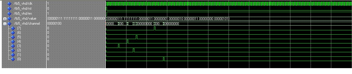
Normalerweise sollten jetzt alle 8 Kanaele asynchron zueinander
arbeiten. Alle 8 Kanaele laufen somit ohne Überlappungen, aber laut der
Simulation sind die einzelnen Kanaele nur einmal kurz eingeschaltet. Ich
hoffe jemand ist so nett und kann kurz meinen Knoten im Kopf lösen.
Bitte melde dich an um einen Beitrag zu schreiben. Anmeldung ist kostenlos und dauert nur eine Minute.