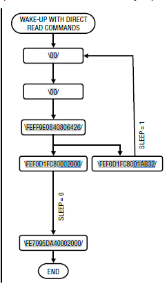
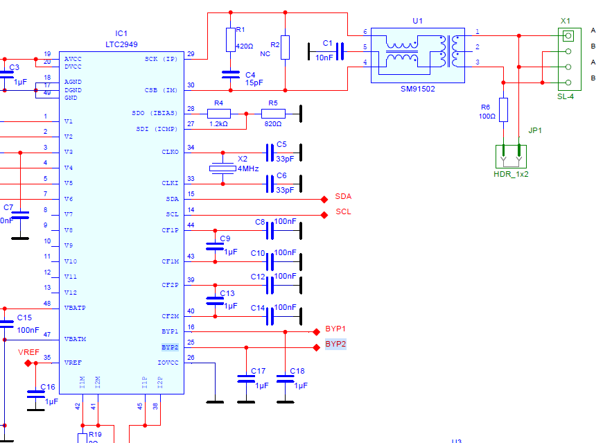
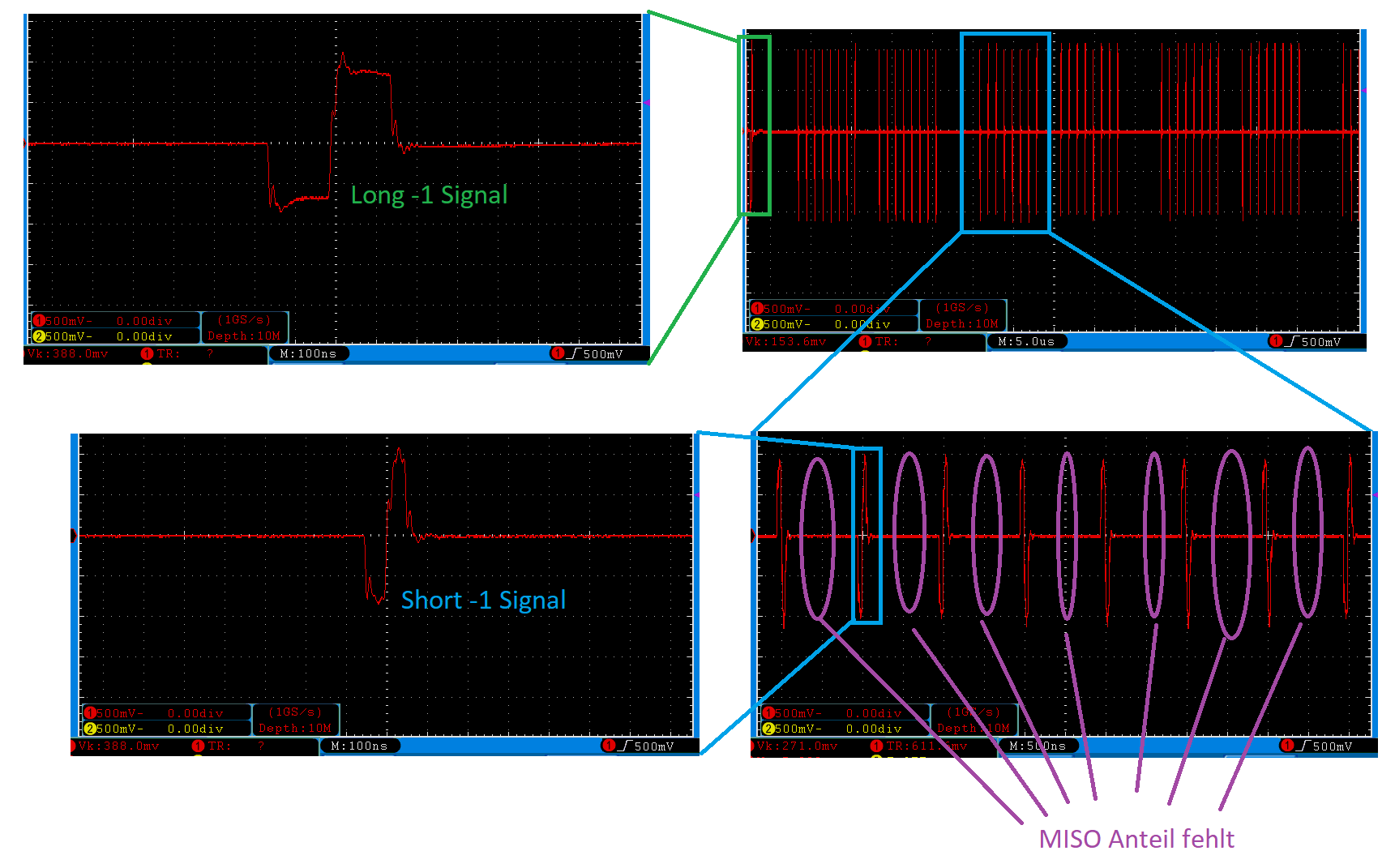
Moin liebes Forum,

ich möchte euch gerne um Mithilfe bitten.

Ich bin gerade dabei ein BMS mit einem LTC2949 und einigen LTC6811-2 zu
realisieren.
Das ganze ist mit isoSPI als Multidrop aufgebaut.
Der Master ist ein STM32F3 mit einem LTC6820 als Wandler.
Leider ist der IC noch recht neu und es findet sich quasi nichts im Netz
zu dem Thema.

Nunja, ich habe aber das Problem, dass sich weder die 6811, noch der
2949 angesprochen fühlen. Die Reaktion ist einfach mal gar keine. Die
Adern vom isoSPI habe ich probehalber getauscht.

Im Anhang befinden sich der Schaltplan und ein paar Messungen von Pin 30
zu 29 am LTC2949.
Die Signale kommen dem Datenblatt entsprechend am IC an, wie man sieht.
Es macht auch keinen Unterschied, ob ich den LTC2949 durch einen
Kurzschluss von SCL auf Masse vom sleep-Status abhalte.

Saft liegt an:

AVCC = DVCC = 12V

BYP1 = 2,5V

BYP2 = 3,3V

IBIAS = 2V

ICMP = 0,8V

Mir ist nur aufgefallen, dass das Quarz nicht arbeitet, beide Pins haben
0V.

Ein wiederholtes Senden des Frames macht keinen Unterschied.
Das Frame habe ich zu Beginn auch stumpf aus dem Datenblatt kopiert, um
Fehler ausschließen zu können, siehe Anhang (Seite 44)

Ich habe das Gefühl, ich sehe den Wald vor lauter Bäumen nicht.

Beste Grüße
Robert
Angehängte Dateien:
-

Frame.PNG
14 KB -

Schaltplan.png
43 KB -

Vip_-_Vim.png
29 KB
Das der Quarz nicht schwingt könnte schon daran liegen, dass der
Baustein zunächst einmal seinen IDLE Modus verlassen muss. In der
überwiegenden Zeit, wo nicht gemessen wird, dürfte der Quarz nicht
schwingen, das wäre verschwendete Energie.

Weiterhin: An Deiner Stelle würde ich zunächst einmal eine Brücke
zwischen zwei LTC6820 aufbauen, ob das überhaupt funktioniert. Das wäre
ja der einfachste Anwendungsfall von isoSPI.
Danke für die Rückmeldung. Das mit dem idle und dem Quarz ist gut
möglich und kann zeigen, warum keine Rückmeldung kommt. Der 2949 käme
demnach nicht aus dem idle. Dann stellt sich die Frage nach dem Warum.
Sleep habe ich ja bereits sichergestellt, sonst wären BYP 1 und 2 auch
aus.

Das Verwenden eines zweiten 6820 habe ich schon probiert. Dort werden
die Signale vom Bus sauber ausgegeben. Die iso SPI Übertragung selbst
scheint wohl nicht das Problem zu sein.
Mit dem 2949 habe ich keine Erfahrung. Aber bei 6812-1 (Sollte sehr
ähnlich sein) sind beliebt:
* Nicht richtig aufgeweckt (siehe Pulse im Linduino code)
* PEC nicht richtig berechnet oder Endianess?
Wie so oft saß das Problem vor dem Bildschirm.
Ich hatte das 5. Byte beim DCMD Kommando falsch, also lesen und
schreiben vertauscht.
Das Schreiben des Registers REGSCTRL ist nicht unbedingt nötig, da die
Standardwerte nach dem Start passen. Es schafft nur eine eindeutige
Ausgangssituation.

Warum ich das Frame direkt aus dem Datenblatt nicht zum Laufen bekommen
habe, verstehe ich rückwirkend auch nicht mehr.

Jetzt läufts.
Für andere mit dem gleichen Problem anbei ein Beispiel. Der DMA muss
natürlich nicht genutzt werden. Ich nutze ihn später und habe ihn gerade
erstmal als Platzhalter im Code.

Konfiguration der Schnittstelle
1 | hspi3.Init.Mode = SPI_MODE_MASTER; |
2 | hspi3.Init.Direction = SPI_DIRECTION_2LINES; |
3 | hspi3.Init.DataSize = SPI_DATASIZE_8BIT; |
4 | hspi3.Init.CLKPolarity = SPI_POLARITY_LOW; |
5 | hspi3.Init.CLKPhase = SPI_PHASE_1EDGE; |
6 | hspi3.Init.NSS = SPI_NSS_SOFT; |
7 | hspi3.Init.BaudRatePrescaler = SPI_BAUDRATEPRESCALER_32; // 1Mbaud |
8 | hspi3.Init.FirstBit = SPI_FIRSTBIT_MSB; |
1 | int8_t LTC2949_Wakeup_isoSpi (LTC2949_t *dev) |
2 | {
|
3 | uint8_t data = 0x00; |
4 | |
5 | HAL_GPIO_WritePin(dev->cs_port, dev->cs_pin, GPIO_PIN_RESET); |
6 | HAL_SPI_Transmit(dev->spi, &data, 1, 1); |
7 | HAL_GPIO_WritePin(dev->cs_port, dev->cs_pin, GPIO_PIN_SET); |
8 | |
9 | return 0; |
10 | }
|
11 | |
12 | |
13 | int8_t LTC2949_Read_Reg (LTC2949_t *dev, uint8_t *data, uint8_t address, uint8_t length) |
14 | {
|
15 | // Compute the frame length and PECC
|
16 | uint8_t frame_length = 5 + length + 2; |
17 | uint8_t pecc = length - 1; |
18 | |
19 | // Set pointers to various parts of the buffers
|
20 | uint8_t *tx_data_1 = dev->tx_buff; |
21 | uint8_t *rx_data = dev->rx_buff + 5; |
22 | uint16_t *tx_pec_1 = (uint16_t*) (dev->tx_buff + 2); |
23 | uint16_t *rx_pec = (uint16_t*) (dev->rx_buff + 5 + length); |
24 | |
25 | // Variables for storing the received PEC and checking for errors
|
26 | uint16_t rx_pec_calc; |
27 | uint8_t rx_pec_error = 0; |
28 | |
29 | // Configure the MOSI frame
|
30 | tx_data_1[0] = 0xFE; // Direct Read/Write Command |
31 | tx_data_1[1] = address; |
32 | *tx_pec_1 = swap_bytes(pec15(tx_data_1, 2)); |
33 | |
34 | tx_data_1[4] = (1 << 7) + (0 << 6); // read command |
35 | tx_data_1[4] += (((pecc >> 3) & 0x1) ^ ((pecc >> 2) & 0x1)) << 5; |
36 | tx_data_1[4] += ((pecc >> 3) & 0x1) << 4; |
37 | tx_data_1[4] += ((pecc >> 2) & 0x1) << 3; |
38 | tx_data_1[4] += (((pecc >> 1) & 0x1) ^ ((pecc >> 0) & 0x1)) << 2; |
39 | tx_data_1[4] += ((pecc >> 1) & 0x1) << 1; |
40 | tx_data_1[4] += ((pecc >> 0) & 0x1) << 0; |
41 | |
42 | |
43 | // Transmit and receive the data using DMA
|
44 | HAL_GPIO_WritePin(dev->cs_port, dev->cs_pin, GPIO_PIN_RESET); |
45 | HAL_SPI_TransmitReceive_DMA(dev->spi, dev->tx_buff, dev->rx_buff, frame_length); |
46 | |
47 | // Wait for the DMA transfer to complete
|
48 | while(dev->spi->hdmatx->State != HAL_DMA_STATE_READY || dev->spi->hdmarx->State |
49 | != HAL_DMA_STATE_READY); |
50 | |
51 | // Release the CS pin
|
52 | HAL_GPIO_WritePin(dev->cs_port, dev->cs_pin, GPIO_PIN_SET); |
53 | |
54 | // Copy the received data to the output buffer
|
55 | memcpy(data, rx_data, length); |
56 | |
57 | // Compute RX PEC to compare it with the transmitted
|
58 | rx_pec_calc = swap_bytes(pec15(rx_data, length)); |
59 | if(*rx_pec != rx_pec_calc) rx_pec_error = 1; |
60 | |
61 | |
62 | // Return error code if PEC error occurred, otherwise return success
|
63 | if(rx_pec_error) |
64 | return -1; |
65 | else
|
66 | return 0; |
67 | }
|
68 | |
69 | int8_t LTC2949_Write_Reg (LTC2949_t *dev, uint8_t *data, uint8_t address, uint8_t length) |
70 | {
|
71 | // Compute the frame length and PECC
|
72 | uint8_t frame_length = 5 + length + 2; |
73 | uint8_t pecc = length - 1; |
74 | |
75 | // Set pointers to various parts of the buffers
|
76 | uint8_t *tx_data_1 = dev->tx_buff; |
77 | uint8_t *tx_data_2 = dev->tx_buff + 5; |
78 | uint8_t *rx_data = dev->rx_buff + 5; |
79 | uint16_t *tx_pec_1 = (uint16_t*) (dev->tx_buff + 2); |
80 | uint16_t *tx_pec_2 = (uint16_t*) (dev->tx_buff + 5 + length); |
81 | uint16_t *rx_pec = (uint16_t*) (dev->rx_buff + 5 + length); |
82 | |
83 | // Variables for storing the received PEC and checking for errors
|
84 | uint16_t rx_pec_calc; |
85 | uint8_t rx_pec_error = 0; |
86 | |
87 | // Configure the MOSI frame
|
88 | tx_data_1[0] = 0xFE; // Direct Read/Write Command |
89 | tx_data_1[1] = address; |
90 | *tx_pec_1 = swap_bytes(pec15(tx_data_1, 2)); |
91 | |
92 | tx_data_1[4] = (0 << 7) + (1 << 6); // write command |
93 | tx_data_1[4] += (((pecc >> 3) & 0x1) ^ ((pecc >> 2) & 0x1)) << 5; |
94 | tx_data_1[4] += ((pecc >> 3) & 0x1) << 4; |
95 | tx_data_1[4] += ((pecc >> 2) & 0x1) << 3; |
96 | tx_data_1[4] += (((pecc >> 1) & 0x1) ^ ((pecc >> 0) & 0x1)) << 2; |
97 | tx_data_1[4] += ((pecc >> 1) & 0x1) << 1; |
98 | tx_data_1[4] += ((pecc >> 0) & 0x1) << 0; |
99 | |
100 | // Copy the data to the transmit buffer
|
101 | memcpy(tx_data_2, data, length); |
102 | |
103 | // Compute the PEC for the second part of the transmit buffer
|
104 | *tx_pec_2 = swap_bytes(pec15(tx_data_2, length)); |
105 | |
106 | // Transmit and receive the data using DMA
|
107 | HAL_GPIO_WritePin(dev->cs_port, dev->cs_pin, GPIO_PIN_RESET); |
108 | HAL_SPI_TransmitReceive_DMA(dev->spi, dev->tx_buff, dev->rx_buff, frame_length); |
109 | |
110 | // Wait for the DMA transfer to complete
|
111 | while(dev->spi->hdmatx->State != HAL_DMA_STATE_READY || dev->spi->hdmarx->State |
112 | != HAL_DMA_STATE_READY); |
113 | |
114 | // Release the CS pin
|
115 | HAL_GPIO_WritePin(dev->cs_port, dev->cs_pin, GPIO_PIN_SET); |
116 | |
117 | // Compute RX PEC to compare it with the transmitted
|
118 | rx_pec_calc = swap_bytes(pec15(rx_data, length)); |
119 | if(*rx_pec != rx_pec_calc) rx_pec_error = 1; |
120 | |
121 | |
122 | // Return error code if PEC error occurred, otherwise return success
|
123 | if(rx_pec_error) |
124 | return -1; |
125 | else
|
126 | return 0; |
127 | }
|
128 | |
129 | |
130 | int8_t LTC2949_Init (LTC2949_t *dev, SPI_HandleTypeDef *spi, GPIO_TypeDef *cs_port, |
131 | uint16_t cs_pin) |
132 | {
|
133 | // Store parameters in device struct
|
134 | dev->spi = spi; |
135 | dev->cs_port = cs_port; |
136 | dev->cs_pin = cs_pin; |
137 | dev->address = 0x0F; // Constant for every LTC2949 |
138 | |
139 | // Initialize PEC15 table
|
140 | init_PEC15_Table(); |
141 | |
142 | // Set CS pin high, low, high to wake up LTC249 core
|
143 | HAL_GPIO_WritePin(dev->cs_port, dev->cs_pin, GPIO_PIN_SET); |
144 | HAL_GPIO_WritePin(dev->cs_port, dev->cs_pin, GPIO_PIN_RESET); |
145 | HAL_GPIO_WritePin(dev->cs_port, dev->cs_pin, GPIO_PIN_SET); |
146 | |
147 | uint32_t start = HAL_GetTick(); |
148 | while(1) |
149 | {
|
150 | // Check if initialization has taken longer than 120ms
|
151 | if(start + 120 <= HAL_GetTick()) return -1; |
152 | |
153 | uint8_t data = 0x00; |
154 | |
155 | // Wake up the LTC2949 twice to ensure it's responsive
|
156 | LTC2949_Wakeup_isoSpi(dev); |
157 | LTC2949_Wakeup_isoSpi(dev); |
158 | |
159 | // Set page 0 and direct read mode in REGSCTRL register
|
160 | data = 0 + (1 << 7); |
161 | LTC2949_Write_Reg(dev, &data, 0xFF, 1); |
162 | |
163 | // Read OPCTRL register to check if the LTC2949 core is in sleep mode
|
164 | LTC2949_Read_Reg(dev, &data, 0xF0, 1); |
165 | |
166 | // Continue looping if sleeping
|
167 | if((data & 0x01) != 0) continue; |
168 | |
169 | // Disable sleep mode
|
170 | data = 0x00; |
171 | LTC2949_Write_Reg(dev, &data, 0x70, 1); |
172 | break; |
173 | }
|
174 | return 0; |
175 | }
|
Ich finde es lobenswert, dass Du überhaupt eine Rückmeldung gibst, die
Beiträge hier sind recht gut bei Google auffindbar.
Ist es denn tatsächlich so, dass der Quarz erst aktiv wird, wenn das
Device korrekt angesprochen wird?
Ich habe hier auch schon Vieles gefunden, dann möchte ich auch etwas
zurückgeben. Und ja, Google macht den Rest :)

Das Quarz schwingt nicht einmal beim Ansprechen, wohl erst beim Messen.
Also erst bei dem Wechsel in den Status measure. Der Status standby ist
etwas missverständlich. Er ist eher als "aktiv ohne zu Messen" zu
interpretieren.

Das Messen ist der nächste Punkt auf dem Zettel.
Hatte mich gefragt, wozu der Baustein dann überhaupt einen Quarz
braucht. Habe mal ins Datenblatt geschaut.

An on-chip oscillator provides a 1% precise time base for calculating
total charge, energy and time. If higher accuracy is required, a 4MHz
crystal connected between pin CLKI and CLKO or an external clock can be
used.
Ich habe mal von einem Vögelchen gehört, dass da ein 8051 drin ist, der
so verschiedene Funktionen (zum Beispiel das akkumulieren) übernimmt ;-)
Was mir nun eingefallen ist, hast due den 2949 bereits? Weil die
Nachfolger adbms295x eigentlich auch verfügbar sind. Vielleicht ist das
noch eine interessante Information...
Bitte melde dich an um einen Beitrag zu schreiben. Anmeldung ist kostenlos und dauert nur eine Minute.
Bestehender Account
Schon ein Account bei Google/GoogleMail? Keine Anmeldung erforderlich!
Mit Google-Account einloggen
Mit Google-Account einloggen
Noch kein Account? Hier anmelden.