1 | component sram_interface is
|
2 | port(--logische Seite des Entities
|
3 | clk : in std_logic; -- Clock
|
4 | we : in std_logic; -- Write Enable
|
5 | reset : in std_logic; -- Reset
|
6 | request_word: in std_logic; -- Anforderung für nächstes Word aus Speicher
|
7 | word_read : in std_logic; -- Signal an Interface, dass Word gelesen wurde
|
8 | word_ready : out std_logic; -- Signal aus Interface, dass Word bereitsteht
|
9 | w_ready : out std_logic; -- Interface zum Schreiben bereit
|
10 | r_ready : out std_logic; -- Interface zum Lesen bereit
|
11 | sram_full : out std_logic; -- Beide SRAM Bausteine voll
|
12 | --data : inout std_logic_vector(15 downto 0); -- Data in/out Bus
|
13 | data_in : in std_logic_vector(15 downto 0); -- Data in Bus
|
14 | data_out : out std_logic_vector(15 downto 0); -- Data out Bus
|
15 |
|
16 | -- physikalische Seite des Entities
|
17 | sram_control : out std_logic_vector(2 downto 0); -- SRAM Control Bits
|
18 | address : out std_logic_vector(17 downto 0); -- Adress Bus
|
19 | sram1_word_enable : out std_logic_vector(1 downto 0); -- Word Enable für SRAM 1
|
20 | sram2_word_enable : out std_logic_vector(1 downto 0); -- Word Enable für SRAM 2
|
21 | data1 : inout std_logic_vector(15 downto 0); -- Data Bus für SRAM 1
|
22 | data2 : inout std_logic_vector(15 downto 0)); -- Data Bus für SRAM 2
|
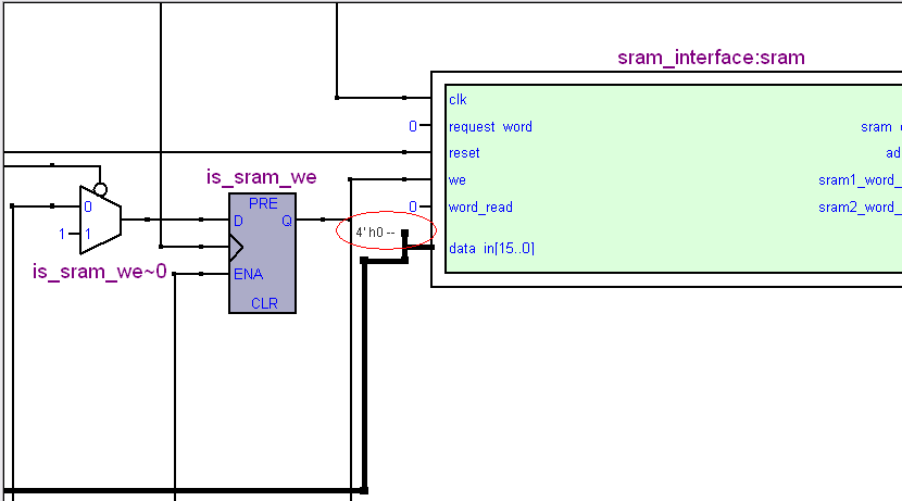
23 | end component;
|
24 |
|
25 |
|
26 | -- logische Signale zu den externen Components
|
27 | signal sram_data_in : std_logic_vector(15 downto 0);
|
28 | signal sram_data_out : std_logic_vector(15 downto 0);
|
29 | signal c_sram_data_out : std_logic_vector(15 downto 0);
|
30 | signal c_sram_data_in : std_logic_vector(15 downto 0);
|
31 | signal is_clk_out_m : std_logic := '0';
|
32 | signal is_sram_we : std_logic := '0';
|
33 | signal is_sram_reset : std_logic := '0';
|
34 | signal is_sram_request : std_logic := '0';
|
35 | signal is_sram_word_read : std_logic := '0';
|
36 | signal is_sram_word_ready : std_logic := '0';
|
37 | signal is_sram_write_mode : std_logic := '0';
|
38 | signal is_sram_read_mode : std_logic := '0';
|
39 | signal is_sram_full : std_logic := '0';
|
40 | signal is_taste_reset_sram : std_logic := '0';
|
41 | signal is_taste_start : std_logic := '0';
|
42 |
|
43 |
|
44 | sram : sram_interface port map(
|
45 | clk => c_clk,
|
46 | we => is_sram_we,
|
47 | reset => is_sram_reset,
|
48 | request_word => is_sram_request,
|
49 | word_read => is_sram_word_read,
|
50 | word_ready => is_sram_word_ready,
|
51 | w_ready => is_sram_write_mode,
|
52 | r_ready => is_sram_read_mode,
|
53 | sram_full => is_sram_full,
|
54 | --data => sram_data,
|
55 | data_in => sram_data_out,
|
56 | data_out => sram_data_in,
|
57 | sram_control => c_sram_control,
|
58 | addressm => c_address,
|
59 | sram1_word_enable => c_sram1_word_enable,
|
60 | sram2_word_enable => c_sram2_word_enable,
|
61 | data1 => c_data1,
|
62 | data2 => c_data2);
|
63 |
|
64 | -- Mappen der internen Signale auf die IOs
|
65 | sram_data_out <= c_sram_data_out;
|
66 |
|
67 | process(c_clk) is
|
68 | begin
|
69 | -- Auf Tastendruck wird das Füllen der SRAM Bausteine mit den ADC Daten begonnen
|
70 | if(init_done = '1' and taste_sram_reset = '1' and (taste_START = '0' or is_taste_start = '1') and is_sram_write_mode = '1') then
|
71 | if(is_taste_start = '0') then
|
72 | is_taste_start <= '1';
|
73 | is_sram_we <= '1';
|
74 | end if;
|
75 | if(is_clk_out_m = '1') then
|
76 | c_sram_data_out(11 downto 0) <= adc_data;
|
77 | end if;
|
78 | end if;
|
79 | end process;
|