Hallo
Ich hab 3 Modulen mit Verilog geschrieben und einzeln simuliert.
Jetzt möchte ich die 3 zusammen verbinden und als ein Block simulieren.
Ich hab schon die 3 v-Dateien in einem verzeichnis gesamelt, ein neues
Projekt unter Quartus II geöffnet, dieses Verzeichnis als Arbeitsbereich
verwendet , die 3 v-dateien zum Projekt eingefügt, und am Ende als Top
level hab ich Block diagram/Schematic File(.bdf) verwendet.
Das Problem ist wenn ich ein Modul einfügen möchte , finde ich es nicht
auf irgendwelche Liste.
Es wäre nett wenn mir jemanden ein paar Tips gibt.

MfG
Sascha
Hast Du Symbole von den Modulen generiert ? Diese müssen vorhanden sein,
um sie in das TLD einzubinden ... ( Kenne mich leider nur mit MAX+plus
aus )
Im Projekt Navigator, Register Files mit der rechten Maustaste auf die
Datei
klicken.

-> Create symbol files for current file

Anschließend kannst du sie in die bdf-Datei einbinden.

Mit der rechten Maustaste auf die Zeichenfläche klicken.

Insert -> Symbol ..

MfG
Holger
Hi,

ich habe gleich noch eine Zusatzfrage:

Ist es möglich in Quartus aus einem Schematic File wieder ein Symbol zu
erzeugen, um es in einem übergeordneten Schematic File wieder zu
verwenden? Das hat bei mir nicht geklappt.

Grüße Stefan
Ist aber meiner Meinung nach nicht zu empfehlen. Erstelle am besten eine
Top-Level Entity in Text, in der du die ganzen Sub-Entities
instanzierst. So hast du immer die volle Konsitenz deines Programmcodes,
denn wenn du irgenwo an einer Stelle im Code was ändern musst, darfst du
nicht vergessen erneut ein Symbol-File zu erstellen und das kann zur
Entwicklungszeit ganz schön nerven...
Angehängte Dateien:
-

PWM.png
3,5 KB
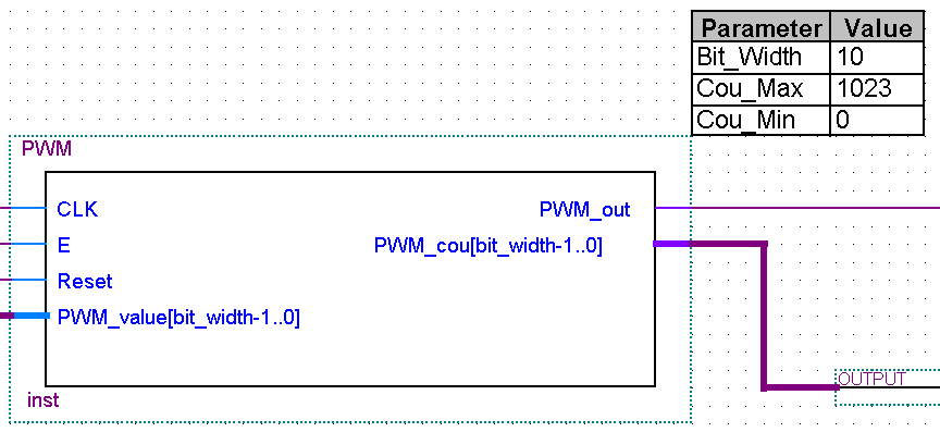
> .. denn wenn du irgenwo an einer Stelle im Code was ändern musst, darfst du
> nicht vergessen erneut ein Symbol-File zu erstellen ..

Solange man nichts an der Schnittstelle ändert, muss man auch keine neue
Symbol-File erstellen.

In der Symbol-File wird nur die entity grafisch umgesetzt.


>> PWM.bdf >>

/*
WARNING: Do NOT edit the input and output ports in this file in a text
editor if you plan to continue editing the block that represents it in
the Block Editor! File corruption is VERY likely to occur.
*/
/*
Copyright (C) 1991-2007 Altera Corporation
Your use of Altera Corporation's design tools, logic functions
and other software and tools, and its AMPP partner logic
functions, and any output files from any of the foregoing
(including device programming or simulation files), and any
associated documentation or information are expressly subject
to the terms and conditions of the Altera Program License
Subscription Agreement, Altera MegaCore Function License
Agreement, or other applicable license agreement, including,
without limitation, that your use is for the sole purpose of
programming logic devices manufactured by Altera and sold by
Altera or its authorized distributors.  Please refer to the
applicable agreement for further details.
*/
(header "symbol" (version "1.1"))
(symbol
  (rect 16 16 320 144)
  (text "PWM" (rect 5 0 30 12)(font "Arial" ))
  (text "inst" (rect 8 112 25 124)(font "Arial" ))
  (port
    (pt 0 32)
    (input)
    (text "CLK" (rect 0 0 21 12)(font "Arial" ))
    (text "CLK" (rect 21 27 42 39)(font "Arial" ))
    (line (pt 0 32)(pt 16 32)(line_width 1))
  )
  (port
    (pt 0 48)
    (input)
    (text "E" (rect 0 0 7 12)(font "Arial" ))
    (text "E" (rect 21 43 28 55)(font "Arial" ))
    (line (pt 0 48)(pt 16 48)(line_width 1))
  )
  (port
    (pt 0 64)
    (input)
    (text "Reset" (rect 0 0 29 12)(font "Arial" ))
    (text "Reset" (rect 21 59 50 71)(font "Arial" ))
    (line (pt 0 64)(pt 16 64)(line_width 1))
  )
  (port
    (pt 0 80)
    (input)
    (text "PWM_value[bit_width-1..0]" (rect 0 0 130 12)(font "Arial" ))
    (text "PWM_value[bit_width-1..0]" (rect 21 75 151 87)(font "Arial"
))
    (line (pt 0 80)(pt 16 80)(line_width 3))
  )
  (port
    (pt 304 32)
    (output)
    (text "PWM_out" (rect 0 0 47 12)(font "Arial" ))
    (text "PWM_out" (rect 236 27 283 39)(font "Arial" ))
    (line (pt 304 32)(pt 288 32)(line_width 1))
  )
  (port
    (pt 304 48)
    (output)
    (text "PWM_cou[bit_width-1..0]" (rect 0 0 121 12)(font "Arial" ))
    (text "PWM_cou[bit_width-1..0]" (rect 162 43 283 55)(font "Arial" ))
    (line (pt 304 48)(pt 288 48)(line_width 3))
  )
  (parameter
    "Bit_Width"
    "10"
    ""
  )
  (parameter
    "Cou_Max"
    "1023"
    ""
  )
  (parameter
    "Cou_Min"
    "0"
    ""
  )
  (drawing
    (rectangle (rect 16 16 288 112)(line_width 1))
  )
  (annotation_block (parameter)(rect 320 -64 420 16))
)

MfG
Holger
Bitte melde dich an um einen Beitrag zu schreiben. Anmeldung ist kostenlos und dauert nur eine Minute.
Bestehender Account
Schon ein Account bei Google/GoogleMail? Keine Anmeldung erforderlich!
Mit Google-Account einloggen
Mit Google-Account einloggen
Noch kein Account? Hier anmelden.