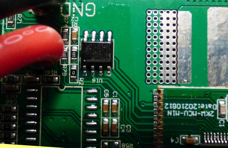
Este un GigaDevice GD25Q40ETIG - cum ai ajuns la concluzia că e
defect?
in primul rind multumesc pentru ajutor ce pot sa spun esee ca dupa extragere a disparut scurt din alimentari adica nu mai existe scurt pe placa de baza
Este un GigaDevice GD25Q40ETIG - cum ai ajuns la concluzia că e
defect?
in primul rind multumesc pentru ajutor ce pot sa spun esee ca dupa extragere a disparut scurt din alimentari adica nu mai existe scurt pe placa de baza
Hallo zusammen,
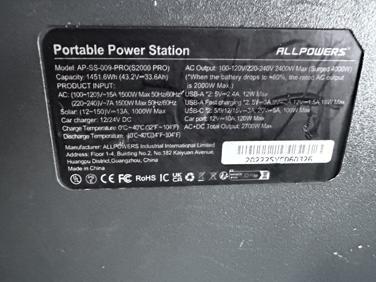
Ich bitte um Hilfe bei der Restaurierung des ALLPOWERS S2000 PRO.
Ich habe vor über 20 Jahren Deutsch gelernt, daher entschuldige ich mich für die schlechte Sprache.
Beim Anschließen der Drähte habe ich einen Fehler gemacht und die Drähte mit den P12- und P6-Steckern verwechselt.
Infolgedessen brannten der N32G455REL7 Prozessor und der GD25Q40ETIGR flash durch.
Ich habe diese Teile und den TM1521B Bildschirmcontroller bestellt.
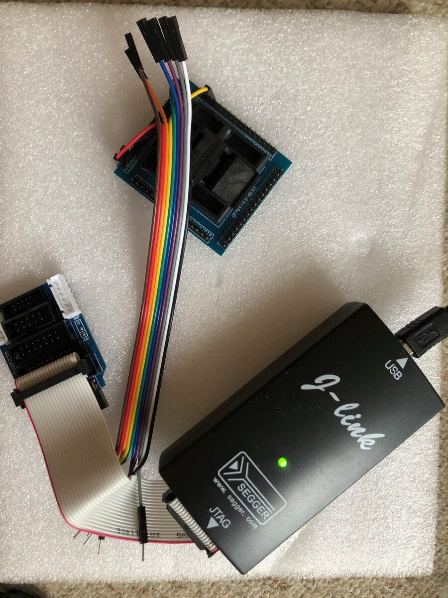
Jetzt habe ich mehrere Prozessoren und USB-Sticks. TM1521B sind noch nicht angekommen. Ich habe einen originalen Segger j-link und einen Xgeku T56 Programmierer.
Ich habe Erfahrung in der Programmierung von flash, aber ich habe nicht viel mit Prozessoren gearbeitet.
Ich möchte versuchen, Prozessor und flash zu flashen.
Wenn es nicht funktioniert, suche ich nach demselben ALLPOWERS S2000 PRO (ich hoffe, sie haben die gleichen Platinen) und versuche, die Dumps vom Arbeitsboard zu zählen.
Ich habe diesen Thread gelesen und die hochgeladenen Dateien heruntergeladen. Aber ich habe ein paar Fragen.
Hat jemand einen Dump für einen GD25Q40ETI-USB-Stick und einen Prozessor von derselben Platine? Ich verstehe nicht, was in GD25Q40ETI gespeichert ist.
Um den Prozessor zu flashen, muss ich das Board vom Akku (P12) mit Strom versorgen, oder reichen 3,3 Volt vom Pad neben dem Prozessor aus?
Kollegen haben drei Archive Allpowers_2000.rar, Allpowers 2000.zip und Allpowers_2000_2.zip gepostet. Ein Archiv enthält eine Allpowers_2000.mot Datei, die anderen 4 Dateien: flash.bin option.bin ram_plus.bin und ram.bin
Sind diese Dateien für ALLPOWERS S2000 PRO geeignet oder für ALLPOWERS S2000?
Ist die .mot-Datei ein vollständiger Dump und der Rest sind separate Teile? Wenn ich j-link über Segger flashen will, welches Archiv sollte ich verwenden?
Muss ich beim Flashen oder Lesen eines vollständigen Dumps die Hex-Adresse des Offsets angeben oder ändern?
No worries, I pasted the uart info below (this thread is super long).
Also, forgot to say, you should use a use a 3.3V bench supply to program the N32G455REl once mounted. It does not need to be connected to the rest of the system
(safer). Once programmed, (carefully connect up to the system).
Also I found it helpful to connect the uart interface , this way you'll know that you
have a successful program. You will get the "RT" banner, just type "help", you'll
get a list of commands most useful especially "iap_reset".
On the Nations MPU daughter board you will find the UART header pins.
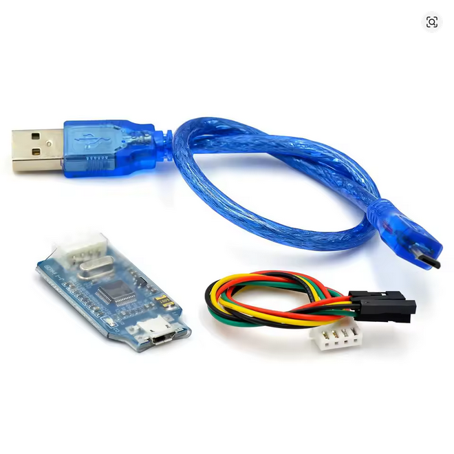
They are screen printed as Gnd,TX,RX, 3.3v. you need to connect header
pins
to Gnd,TX and RX only (don't connect 3.3V).
Connect the cable as follows:
Nations MPU daughter board CP2101
Gnd-------------------------->Gnd
TX--------------------------->RX
RX--------------------------->Tx
(don't connect 3.3v)
Run Putty in serial mode and select correct com port use baud
rate of 115200, click connect. This will open a second window.
You should see "RT thread 1.03 banner", then type "help" and
you will see a list of diagnostic routines.
For example, "dc_sw" will toggle the DC switch on the front panel and
"battery_data_debug" will show status on battery data coming from the
BMS.
Another useful one is "iap_reset", this will reset the MPU.
Ich habe es herausgefunden. Der Prozessor blinkte. Es gab eine Nachricht, dass es unmöglich sei, einen Sektor aufzuzeichnen. Trotzdem hat die Lünette begonnen. Ich repariere es weiter.
I restored the 3.3 volt power supply and the front panel started up.
But it does not "see" the battery BMS.
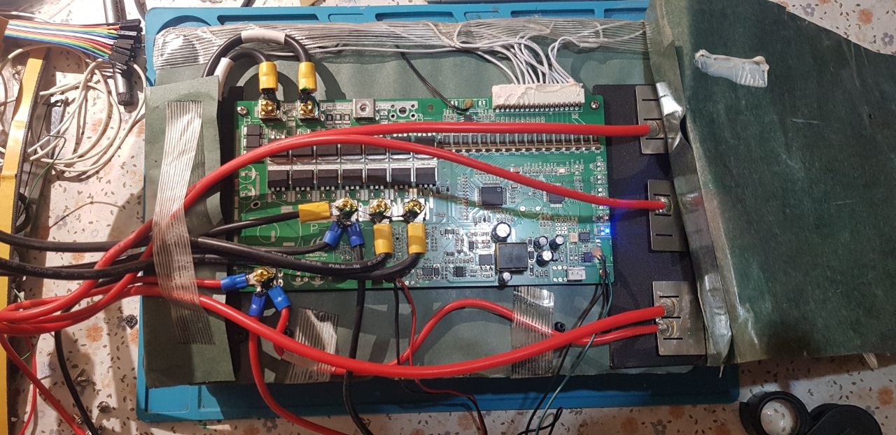
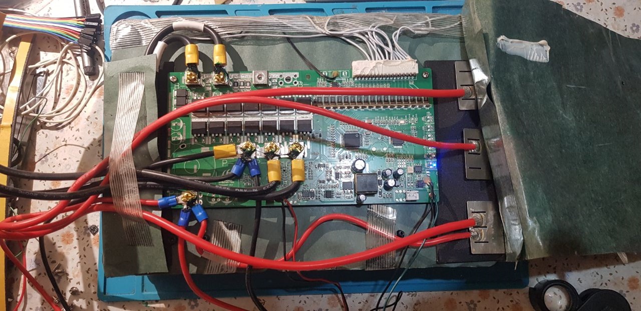
I lifted the cardboard covering the BMS. At first glance, I didn't see anything burnt.
Apparently, the battery BMS cable is connected to the MPPT controller cable, and from there, the signal returns to the board.
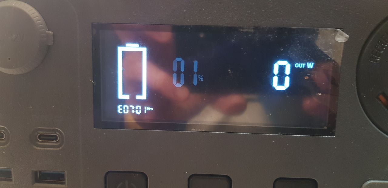
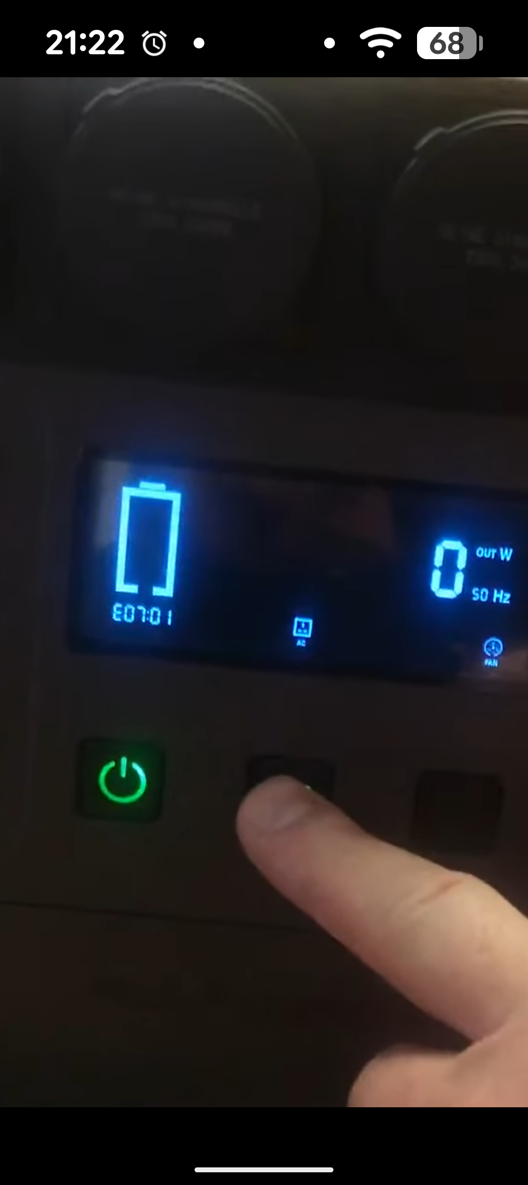
Now the error E07:01 is on the screen.
Both with all the wires fully connected and when starting simply by supplying power to the 50 volt connector via XT60.
The E07 error has already been mentioned in this thread, but I still don't understand if anyone has solved this problem.
Perhaps the Allpowers_2000.mot dump is not suitable for my board or cannot work with the battery BMS.
I want to try to make a copy from a similar S2000 Pro
Tell:
There's a copy of the thread, piece by piece. Has anyone flashed a processor this way? What's the sequence?
The processor is not locked, right?
Has anyone done a dump from the battery BMS and does it make sense to do so?
So, how do I reset the battery's BMS? There are no buttons, and disconnecting the positive cable didn't help.
I also have battery connection error E07.
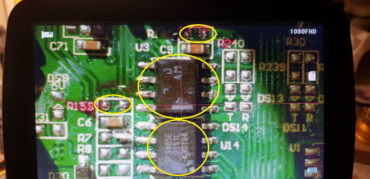
I found the SP3485E chip on the display board.
You wrote that it is under the battery.
Is this chip on the back of the BMS board?
The Command "drv_rs486_receive_debug" shows raw data coming from BMS.
"pv_data_debug" for PV data and "ac_data_debug" for inverter.
Use "iap_reset" to stop data stream, it's possible to type in console
while it's streaming.
I wish I had working power stations so I could see what data looks like
on working power stations. Maybe people with working units could put up
data streams captured from their systems. I will help us unfortunate
people
with non working units to get some idea on what's happening in their
units.
Also can we start sharing any further discoveries as to commands in the
UART console.
Hope that helps.
Fred.
Hi Fred, you were right, the problem with No battery data and error 701
was indeed one of the rs485 trancivers, that on the battery to be exact.
I replaced it and now i have battery data! Here it is:
Hello!
I also have battery connection error E07.
I found the SP3485E chip on the display board.
You wrote that it is under the battery.
Is this chip on the back of the BMS board?
Thanks everyone for your help!
The device is almost restored.
The board detected the battery and the E07 error disappeared.
The Bluetooth module doesn't work, but that's not a big deal.
Leider keine Verbindung, eine Fenster öffnet sich aber ohne Meldung !
Besten Dank im Voraus ...
Hello.
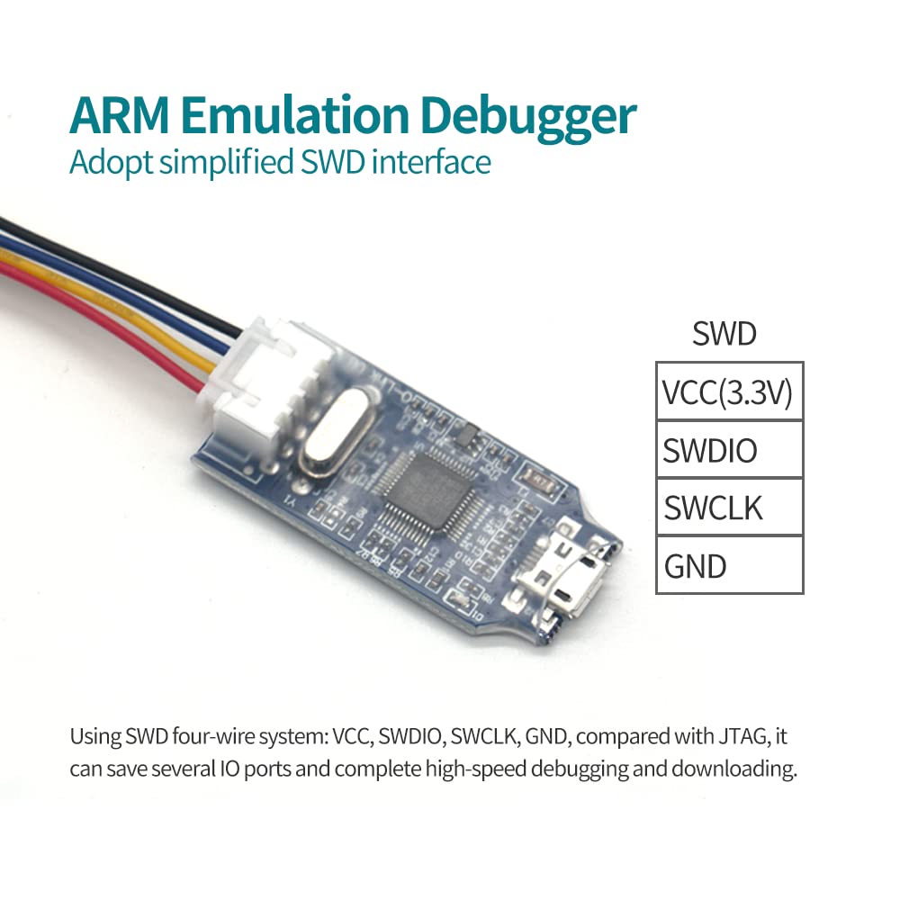
I used Jlink and SWD mode. It's a different operating mode and a different connector.
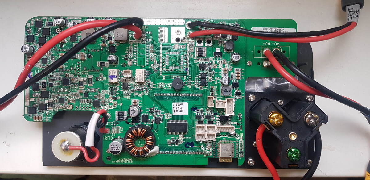
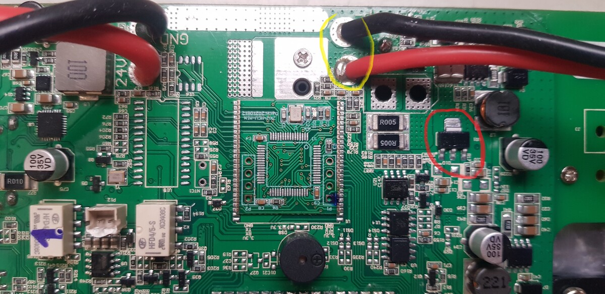
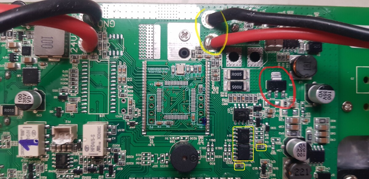
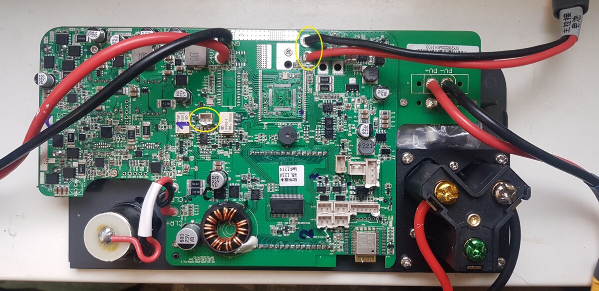
You can power the display board by applying 24-50 volts to the connector highlighted in yellow.
Also check for the presence of 3.3V processor supply voltage on the middle leg of the stabilizer, highlighted in red.
Colleagues, I have another question about the Allpower 2000 Pro.
After the charge and discharge cycle, a problem appeared.
If the battery is discharged, after connecting the 220 volt cable, clicks are heard, there is an attempt to start (the screen blinks), but the station does not start.
I partially charged it through the PV input.
After that, I started it with the button, connected 220 volts and charging started.
Now the battery charge is 100%.
In the off state, after connecting 220 V, the station does not start.
(there are clicks, the screen is flashing)
If you turn it on (press the button for a few seconds), the station starts.
After that she determines 220.
Is this a problem with the soft starter on the inverter board or the secondary power supply unit?
Or is this a software error?
Or is this normal behavior for such stations?
USB Param. : (USB\VID_1366&PID_0101), und jetzt werde ich mal damit herumspielen.
7
8
Frage: Muss das ausgebauetes Board mit 24-50V DC wie Alex das beschrieben hat während des Programmieren gespiesen werden, und dann nur die SWD signale anschliessen ohne 3.3V ?
9
10
Board P1 <--> Segger J-Link driver v2.70.8.0 unter Win11
Es scheint das die FW vorhanden ist ... Aber keine Spüren von Display Lebenzeichnen !
86
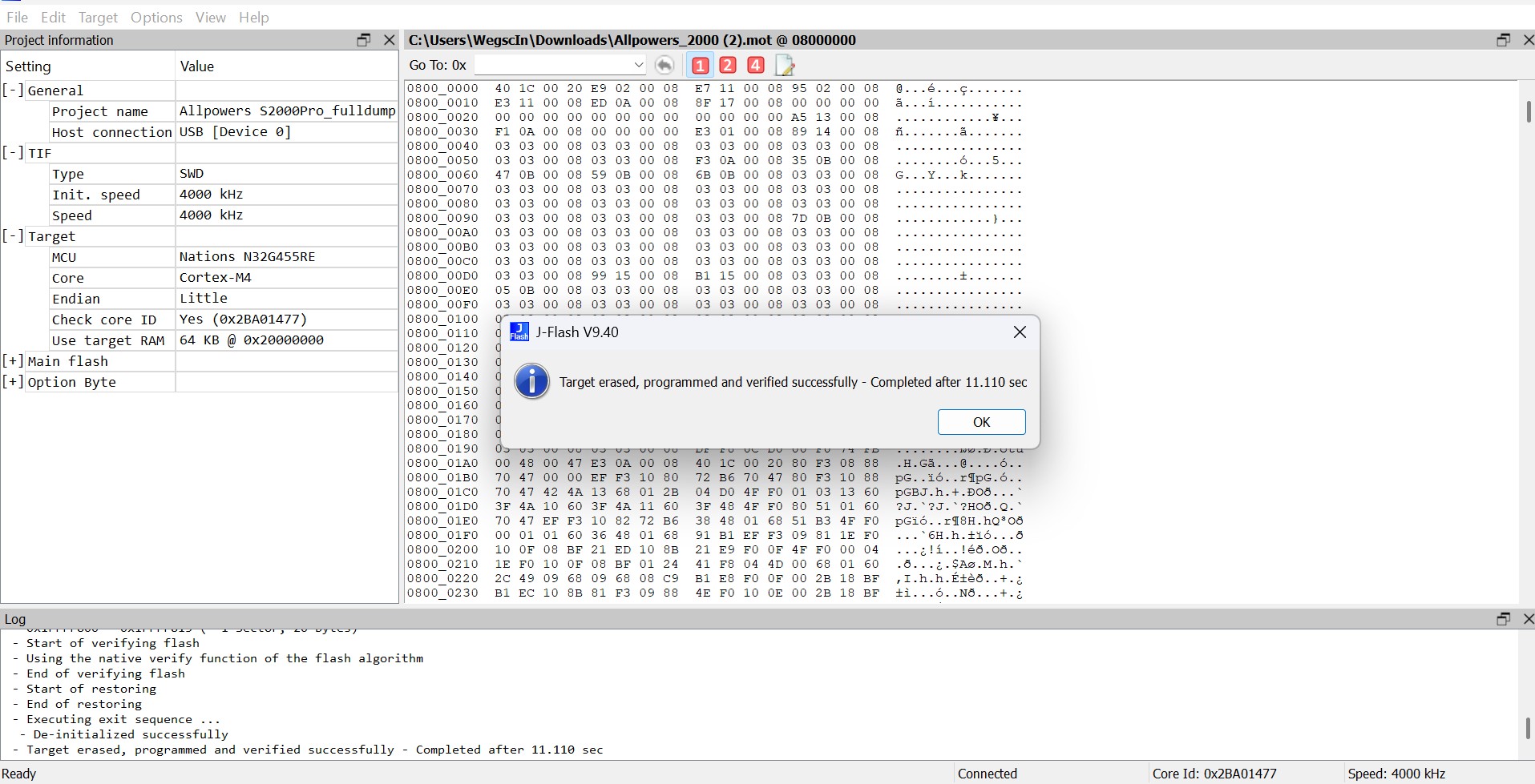
Frage : Jetzt möchte ich wissen wie man die SW überprüfen, herauslesen und ev. neu beschreiben kann (ALLPOWERS_2000.mot-1310788) (mit SEGGER_JFlash_v886 oder weiterin SEGGER_JLink_Commander_v886) ...
87
88
So genug für heute, ich hoffe ein "ALLPOSERS" Guru can uns weiter helfen ...
I decided to write a post about my experience with AllPower 2000 Pro repairs.
Many thanks to everyone who helped me with the repair!
I think this information may be useful to someone in further repairs.
So, first one and then 2 more such devices were brought to me for repair.
Initially, they all had the same problem – missing 220 on the output connector.
Usually this indicates that one of the 2 fans per inverter is not working.
It is easy to identify the problem - after starting, one of them begins to rotate and stops.
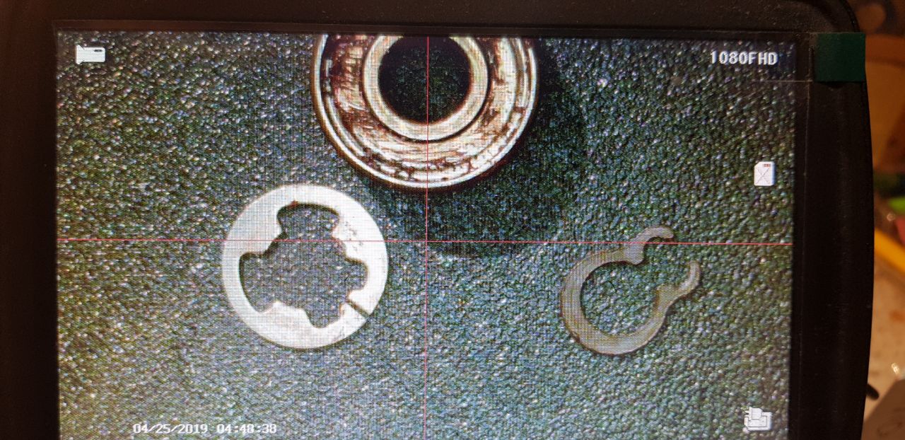
The problem is that over time, moisture gets into the lower bearing (the one that is closer to the sticker), the process of its destruction begins and, in the end, the retaining ring that holds the shaft wears off.
The impeller shifts forward under the action of a spring, and the fan speed sensor stops working.
The repair is simple: you need to remove the fan, clean the hole, replace both bearings (outer diameter 8 mm, inner diameter 3 mm, height 4 mm) and the retaining ring.
I bought EZO bearings and 3mm retaining rings in China. I recommend adding a little lubricant.
There are also stainless steel bearings, but I did not find them in this size.
In the first photo, the damaged bearing, a round retaining ring and an analogue.
To install a new retaining ring, you need a tube with an internal diameter of 3-3.5 mm.
The rest of the problems I had after I mixed up the wires from:
standby power supply from the battery (24 volts) and DC-DC inverter power cable 56 V 24
24 volt cables from DC-DC inverter 56 V 24 (its output) and 56 volts from the battery.
It was a very bad day....
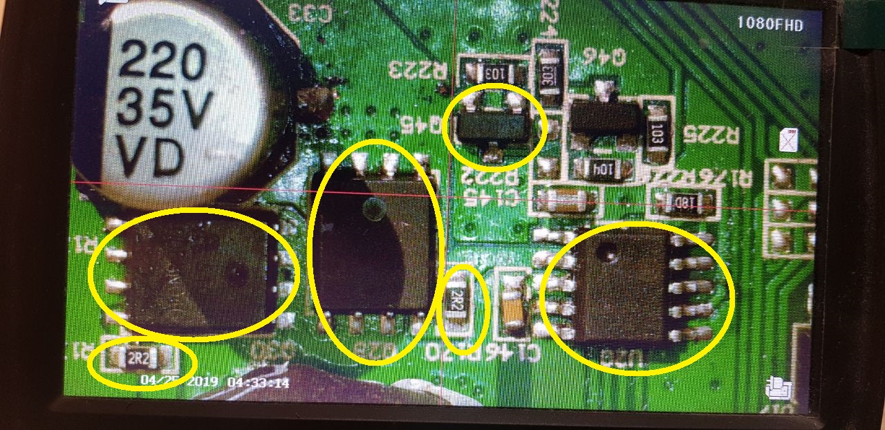
In the first case, I applied 24 volts to a 3.3 volt power line and burned the hell out of everything on it: the processor, flash drive, CAN and RS485 interfaces, Bluetooch transmitter and various logic circuits.
To fix all this, you need:
Processor and programmer.
Flash memory chip
CAN and RS485 Interface Controllers
3.3 volt stabilizer
P channel mosfets in the SOT-23 package (some kind of analogue of the 3401)
Resistors 2.2 ohm size 603
First, I replaced the processor and flash memory chip. I flashed the processor with a full dump, which is earlier in this topic. I have a J-link and have used it in SWD mode.
For the flashing, I used an external 3.3 volt power supply, as my colleagues advised earlier. But I think you can supply about 24 volts to the right power connector (56 from the battery) and, if the 3.3 volt stabilizer is working, you can work. But it did not work for me and I replaced the stabilizer.
The board started, but it didn't see the battery (error E07). The reason is that the RS485 interface controller (communication with the battery's BMS) and the 2.2 ohm resistor in its power circuit burned out.
The situation is similar with the CAN bus controller and the resistor in its power supply circuit.
After replacing these elements, the processor saw the battery.
But, there was a strange problem - in the off state, when connecting 220 volts to the input, the board did not start. The relays clicked, the screen flashed and that's it. If you start the board first, and then apply 220, the charge began.
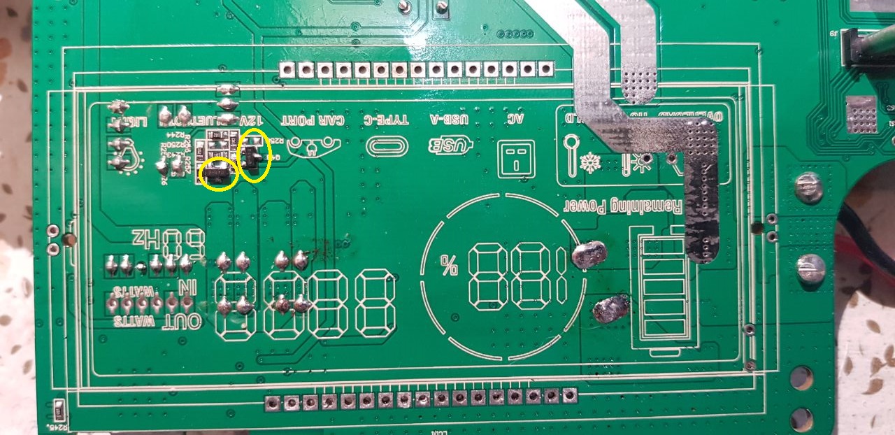
The reason for this behavior is constant 3.3 volts on enable line DC-DC supply (56 V to 24V)
The control circuit of this line is located under the screen. I had to goutweed the screen and replace 2 3401 FETs.
After that, the fee worked normally.
But I also burned the 12 volt😊 line
To repair it, I replaced the PWM controller NDP1415RB, 2 APG068N04G keys and 2 2.2 ohm resistors in the gate circuits.
5 volts began to appear on usb.
It turned out that another 3401 key next to the PWM controller burned out.
After his replacement, almost everything worked.
I didn't find the Bluetooch module. In fact, it is not needed.
With a 3 station discharge test cycle, I will notice the following:
One of the stations discharged the battery to 0 percent (another stop discharge process on 5 %). After applying 220 volts to the input, error E07 appeared. The station began charging. When the battery reaches 1 percent, the error is gone.
Fans were repaired at this station.
At the second station, the connection with the battery periodically loses during charging (error E07). At the same time, the charge continues. After a while, the error disappeared
Benötige Firmware für die Frontblende der Ladestation.
Allpower AP-SS-009 (S2000) ohne Pro.
Chip N32G455VEL7 ist neu.
Alt, defekt (Kurzschluss).
Die auf der Website angebotene Firmware funktioniert nicht.
Beim Drücken des Knopfes piept die Station, schaltet sich aber nicht ein.
Es wird auch kein Bild auf dem Display angezeigt.
Zum Programmieren verwende ich den J-Link Programmer.
Ich melde mich wieder mit eine für mich ungeklarte Frage (Sie würde früher mehrmals getellt aber unbeantwortet - Fred F.(fred007)!) :
Es werden verschiedene BIN->MOT->BIN Tools im WWW angeboten, aber die Einstellungen ist ziemlich heikel um etwas nurtzliches zu erreichen.
Es ist mich gelungen meine "ALLPOWERS S2000 PRO" durch flaschen des "flasch.bin" und SEGGER J-Link Commander endlich wieder zum leben erweckt ... Danke an Euch alle für die Tips und Tricks !
Meine Frage lautet :
Da verschiedene *.mot (Motorola S-Record SREC) Dateien in diesem Forum angeboten werden (Martin M. bmw_power und Szabolcs Z. szabolcs_z), möchte ich wissen wie sie hergestellt werden und mit welche SoftWare, die Verbindung klappt bei mir problemlos mit einen CN J-Link Clone Interface und die SEGGER J-Link Commander SoftWare im SWD Modus.
bietet noch irgendjemand hier aus dem Forum die Reparatur der ALLPOWERS S2000 PRO gegen Übernahme der Unkosten an?
Kai B. (schorni) hatte ja letztes Jahr eine entsprechende Annonce dazu auf kleinanzeigen.de, aber die ist inzwischen leider offline.
Ich hätte auf jeden Fall Interesse! Der Fehler ist der mit dem zu geringen Ladestrom über Solar in der Dämmerung, also alles genau, wie hier im Thread beschrieben. Entweder in der Nähe von Berlin oder mit Versand (natürlich unter Einhaltung der Verpackungs- und Kennzeichnungspflichten von DHL).
Vielen Dank für Eure Hilfe, ich bin über jeden Hinweis dankbar! :-)
Mit großem Interesse habe ich mich heute durch diesen Beitrag gelesen.
Toll was hier abgeht - ich repariere normalerweise nur EcoFlow-Geräte und die sind schon in einer ganz anderen (hochwertigeren) Liga.
Jedenfalls habe ich mir eine S2000-Pro gebraucht geholt und offensichtlich dürfte es hier dasselbe Problem geben.
Das LCD und DC leuchtet zart beim Anschließen der 3,3V-Spannung. Zu mehr bin ich noch nicht gekommen, denn mir fehlt der Segger-Adapter (habe mir den gerade bestellt).
Bin schon gespannt, ob ich das hinbekomme. Software ist nicht so mein Ding aber ich habe hier viel Durchhaltevermögen.
Eine ganz andere Frage. Der Vorgänger hat das Gerät schon geöffnet und mit Bleistift (!) die Stecker und Buchsen beschriftet. Das ganze ist natürlich kaum lesbar und wurde vom Vorgänger schon verwischt.
Wahrscheinlich hat niemand einen Plan was wo angesteckt wird, oder?
Die wichtigste Frage für mich ist: ist im Ruhezustand (Gerät abgeschaltet und nicht an der Steckdose angeschlossen) der 230V-Eingang (Kaltgeräteanschluss an der Rückseite) direkt auf die Schukobuchsen und die seltsame Camping-Buchse an der Vorderseite verbunden??? Diese XT60-Stecker und XT60-Buchsen waren überhaupt nicht angeschlossen und offensichtlich sind hier alle 230V-Anschlüsse mit dem Kaltgeräteanschluss verbunden. Anders kann ich mir das nicht erklären.
Wahrscheinlich wird dann ein Relais bei Ladebetrieb die Kaltgerätebuchse von den Buchsen an der Vorderseite trennen.
Vielleicht kann ja wer mal nachsehen. Dankeschön :-)
Freue mich über Eure Nachrichten und bin gerne bereit hier mitzumachen.
Liebe Grüße aus Österreich und einen schönen Feiertag
ich repariere normalerweise nur EcoFlow-Geräte und die sind
schon in einer ganz anderen (hochwertigeren) Liga.
Contra. So oft wie diesen ach so großartigen Powerstream-Erweiterungen für Balkonkraftwerke der Arsch platzt wenn man sie ohne zusätzliches Lüfter-Kit betreibt, kann man wohl kaum von hoher Qualität sprechen. Und die Probleme mit tiefentladenen Akkus, nicht mehr funktionierenden Power-Stations hat Ecoflow leider ganz genau so wie andere Hersteller. Außerdem unverschämt hohe Preise für ihre faltbaren Solarmodule, die ebenfalls nicht lange funktionieren wenn man sie (bestimmungsgemäß) oft faltet. Auf meiner Suche nach brauchbaren Teilespendern (mit angemessenem Preis) sehe ich immer wieder defekte Ecoflow-Produkte, nicht weniger als welche von Allpowers. Die Technik scheint überall noch nicht ganz ausgereift zu sein.
Greetings!
Without 220, there are two live connectors on the front panel: the standby battery - there are 57 volts (small connector #1) and 57 volts on the large connector.
The rest is without food.
If you apply 220 to the inverter input, it should switch to battery charging mode and 24 volts should also appear on the additional power supply (this connector is also connected to the front panel with 24V parking)
If there are no markings or labels on the connectors, it's annoying, but not fatal. You can use adhesive residue to guide you.
Or, translate the inscriptions on the cables.
Of the small connectors on the front panel, one is for the fan, and one (the green cable) is for the battery's BMS. I don't remember what the third one is.
The main thing is not to confuse the duty and power parts when connecting the front panel.
Weak backlight is most likely due to degradation of the backlight LED.
But you need to remove the screen.
Thank you for your useful explanation. I have only 46V (maybe the battery is a little bit discharged due to the winter as the former-owner told me) but only on the small connector #1.
Nothing (0,0V) on the upper-right (yellow-marked) connector.
That's what made me confuse after I've opened the box. I don't know if the battery is "too discharged" to recharge it with the internal BMS.
I'll check that today or tomorrow.
By the way:
Do you or does one know the total amount of the batteries and how they are connected together?
According to the picture here, these are 21700 cells with 15,84Wh (4200mAh) inside.
I assume (due to the BMS sensor-cables in the picture) there should be 12 or 13 batteries serial and each rowk could have 7 or 8 cells in parallel to get to the theoretically 1500Wh.
In this case, the BMS is blocked and does not output voltage.
Remove the battery, lift the cardboard, and you'll reach the battery's BMS board.
There should be a balancing connector for each cell. This connector allows you to check the cell voltage.
If there is a large imbalance, it is possible that some cells are out of order.
You can check them without full disassembling, if you disconnect the balancing connector and disconnect the "+" from the BMS board.
But, as far as I remember, it’s not easy to do this – the design and installation are not very good.
But then you can test (charge/discharge) the cells one by one.
Look at the bottom of the case - the battery voltage is indicated there.
If I'm not mistaken, it should be about 56 volts.
You can try to recharge the battery by applying 56 volts to the "+" "-" input of battery.
Do you or does one know the total amount of the batteries and how they
are connected together?
According to the picture here, these are 21700 cells with 15,84Wh
(4200mAh) inside.
I assume (due to the BMS sensor-cables in the picture) there should be
12 or 13 batteries serial and each rowk could have 7 or 8 cells in
parallel to get to the theoretically 1500Wh.
Thank you
Most likely it's 16S, judging by the connector. 3.65*16=58
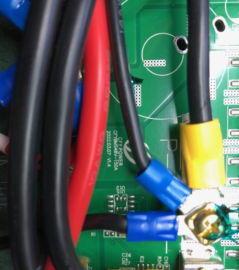
Oh yeah, I found the photo. It's all very simple - just bolts.
Thank you again ... I'll check it today evening.
I know how to charge them and if cells are weak I always replace them.
Maybe one block has been fully discharged (if one cell has a short-cut).
Welding-stuff and all necessary connector-frames I've at home.
I'll tell you tomorrow.
WARNING FOR ALL USERS:
Keep always in mind that deep discharged batteries (< 2,8V) must not be recovered.
Firstly it doesn't make any sense because the capacity is very low.
Secondly most batteries develop to live and got warm, even if they are not in use for days until they are fully discharged. (First step before thermal-runaway.
I know how to charge them and if cells are weak I always replace them.
Maybe one block has been fully discharged (if one cell has a short-cut).
Dear Ingo W,
Tell me, do you change only one cell or all the battery elements?
We've had broken batteries with this problem. We usually replace all the elements, as it's difficult to find batteries with similar resistance and capacity.
first of all, the batteries are all good and not discharged. Every cell-pack has exactly 3,98V.
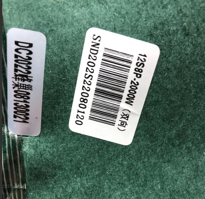
I don't know why you got 56V - my pack is a 12x8 pack so in total 96 cells.
So total-voltage is around 48V.
Maybe there are other versions out in the field.
I normally got my batteries at a local dealer which unfortunately closed the shop due to retirement.
18650 batteries you can get anywhere
21700 batteries are pretty difficult but you can get them at Alibaba or another distibution-channels
If one pack is defective, I usually exchange the whole pack. Of course it makes sense and the rest is in a good condition.
I've built a lot of capacity-measurement units over the last 30 years so I check every pack before if they are good and use batteries with the same capacity to avoid imbalance.
Yesterday I've double checked every voltage-regulator, diodes, transistors and resistorts.
After connecting the two small plugs (from the battery) to the front-panel, and pushing the left button "power-on" I've also got the voltage on the large connector but still no display, no USB, no AC.
I think the MCU is the problem, even it was never used with solar-panels (according to the pre-owner). The MCU-board has 3,3V and the green LED is on. Also the LCD-backlight is on.
I've ordered the programm-stuff from Jaegger and try to reprogram it....
I apologize for providing incorrect voltage data.
I wrote this from memory, since the exact voltage values on the connectors are not recorded on paper.
Before replacing the proсessor, if I were you, I would try to erase the existing one and write a dump from this branch into it.
I repaired my last AllPower 2000 Pro exactly this way.
I used J-link, SWD mode and a separate 3.3 volt power supply for this.
Kann mir iwer bitte bitte helfen ich habe 0 plan was los ist, meine s2000 gibt noch strom, aber frau hat vergessen solar ab zu stecken im garten, und jetzt geht keine Bedienung mehr display auch nicht bekomme sie nicht mal mehr aus, ich bin völlig verzweifelt. Weiss wer wo man das machen lassen kann ???
Kann mir iwer bitte bitte helfen ich habe 0 plan was los ist, meine s2000 gibt noch strom, aber frau hat vergessen solar ab zu stecken im garten, und jetzt geht keine Bedienung mehr display auch nicht bekomme sie nicht mal mehr aus, ausschluesslich dc leuchtet konstant leicht grün, ich bin völlig verzweifelt. Weiss wer wo man das machen lassen kann ???
willkommen im Club ... meine hat denselben Fehler :-)
Wahrscheinlich das berühmte Problem mit dem Nation MCU.
Ich habe mir vorigen Sonntag das Programmierkit und einen neuen Prozessor samt Halterung bestellt um zu experimentieren. Sobald die Teile aus China angekommen sind, probiere ich den MCU neu zu programmieren und melde mich dann.
Glad to see that this thread is getting busy again. I still haven't found the time to fix my box unfortunately, but if someone in or around Berlin already bought the programming kit, I'd be happy to join forces.
Another question: Has anyone found a way to fix this problem for good so it won't happen again with weak solar?
nachdem ich gestern endlich den J-Link Adapter von Segger erhalten habe, habe ich mich heute am Feiertag gleich dran gemacht und versucht das Gerät zu programmieren. Leider wollten meine beiden Laptops (Dell und Toshiba) absolut nicht mit der Software und dem J-Link zusammenarbeiten. Mit dem Setup für die USB-Treiber (werden in einem Unterverzeichnis mitinstalliert) hat es dann aber funktioniert.
Ich konnte mich dann auf den MCU verbinden, nur waren bei mir überhaupt keine Daten mehr drauf - entweder verschwunden oder vom Vorgänger gelöscht.
Somit habe ich den MCU nochmal komplett gelöscht und dann das File von Heiko Allpowers 2000_2.zip heruntergeladen. Da sollten ja alle Files für die Allpowers S2000 Pro enthalten sein.
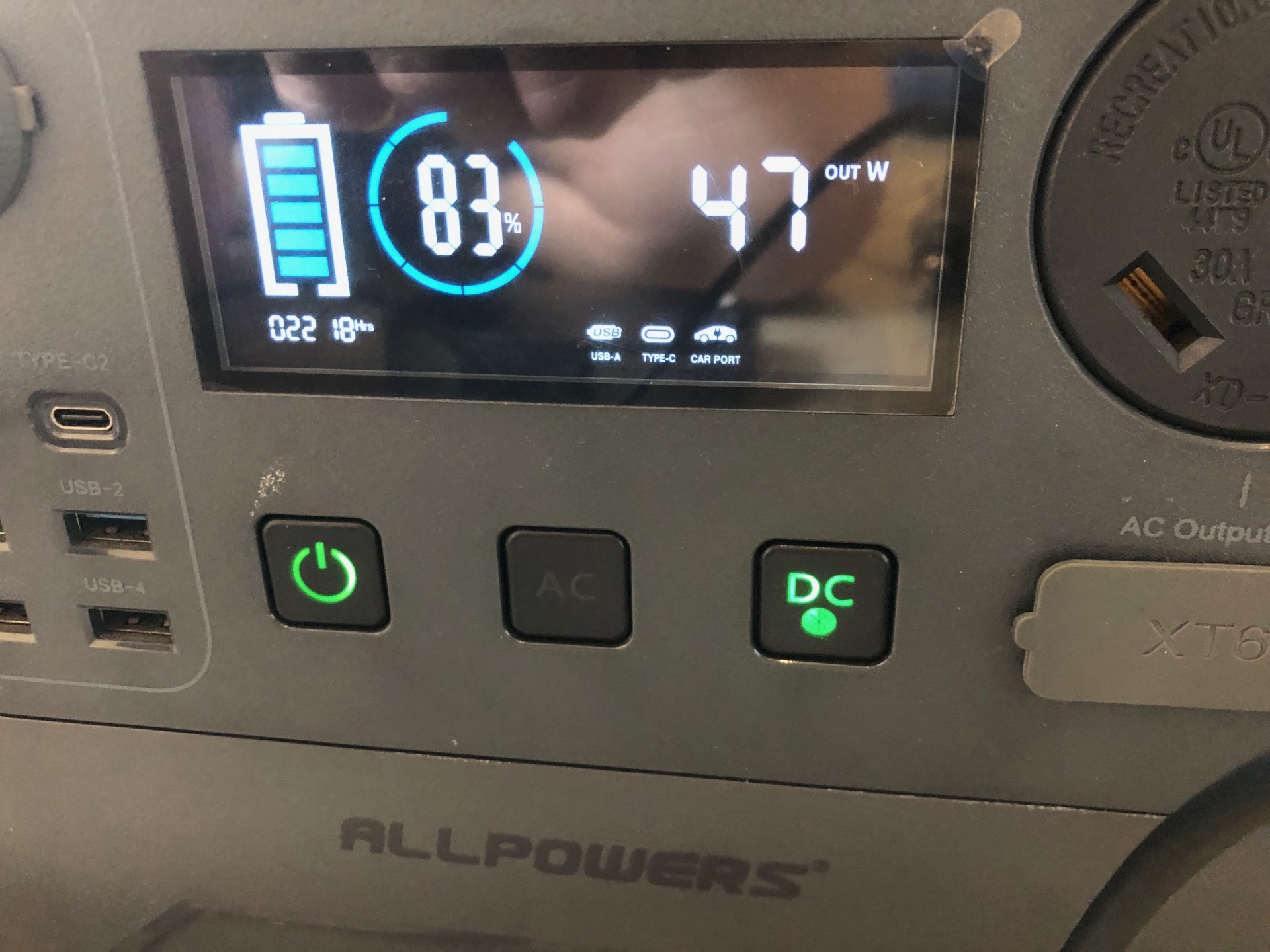
Ich habe (nachdem der MCU komplett gelöscht war) das File flash.bin aufgespielt und siehe da das LCD kam wieder mit 83% und die Funktionen haben gleich alle gut funktioniert (auch Bluetooth).
Vor lauter Freude habe ich darauf vergessen mich um die anderen Files option.bin / ram.bin / ram_plus.bin zu kümmern.
Hätte ich die auch aufspielen müssen? Hat es irgendwelche Auswirkungen wenn die nicht drauf sind?
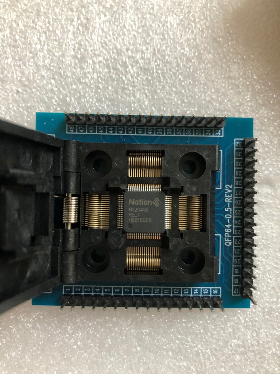
Interessehalber habe ich mir gleich einen baugleichen MCUs mitbestellt und in einem LQFP64.Sockel eingesetzt.
Nachdem da offensichtlich schon irgendwelche Daten drauf waren, habe ich den auch gelöscht.
Dann habe ich auf diesen MCU das flash.bin file aufgespielt und verglichen mit dem File von Heiko. Alles in Ordnung.
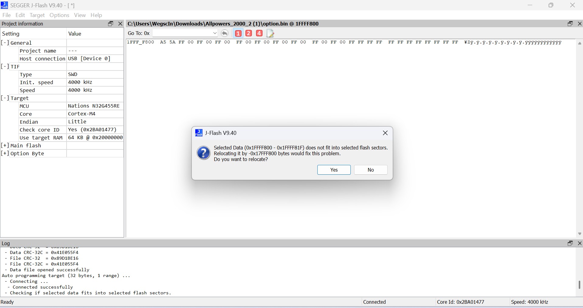
Hernach wollte ich dann noch option.bin aufspielen und habe als Adressbereich 0x1FFFF800 angegeben worauf ich dann folgenden Meldung erhalten habe:
Selected Data does not fit into selected flash sector...
Habe ich da einen Fehler gemacht oder hat sich etwas verschoben? Ich habe das leider nie in der Schule gelernt aber mit 55 Jahren ist man ja trotzdem noch lernfähig :-)
Wichtiger wäre mir jedenfalls ob ich die Kiste nochmal öffnen soll um um die Files option.bin / ram.bin / ram_plus.bin nachzuladen...
Herzlichen Dank für Eure Hilfe und einen schönen Feiertag
Flash.bin reicht - die Option Bytes sind für Schreib- und Leseschutz da und können nicht einfach aufgespielt werden - sie sind sozusagen nur zum Auslesen und zum Vergleich da. Ich tippe darauf, dass dein Chip nicht leer sondern lesegeschützt war - hätte man an den Option Bytes ablesen können - die grüne LED war doch bestimmt an wenn man versucht hat anzuschalten.
Den Datenspeicher brauchst du auch nicht zurückspielen - der wird bei Programmstart „bevölkert“.
Zu guter Letzt habe ich die Kiste nochmal geöffnet, alles abgesteckt, den MCU gelöscht und statt der Flash.bin dann die Allpowers_2000.mot hinaufgespielt.
Das Ergebnis ist (wie schon von Martin geschrieben) dasselbe.
Die Kiste funktioniert so oder so mit einer beiden Files.
Und den zweiten MCU (habe den im Sockel programmiert) habe ich ebenfalls mit der Allpowers_2000.mot programmiert und hebe mir den in der Allpowers-Ersatzteilbox auf.
Hallo liebe AllPowers Geschädigte ;o)
mein Name ist Ralf und ich wohne seit Oktober als Ruheständler in der Pusta Ungarn.
Da hier ab und zu der Strom ausfällt, hab ich meine S2000 pro mit 4050 w Panel als Reserve genutzt.
Leider ist genau der selbe Fehler , wie bei fast allen Nutzern aufgetreten. Seit Wochenende, beim zweiten mal Laden durch s Panel auch der Fehler ... Display tot und DC Taste glimmt ...Es läßt sich nix ein oder ausschalten.
Nun bin ich zwar gelernter Diagnosetechniker aber eben für PKW Fehlersuche.
Mit Flash und proggen kann ich leider nicht.
Könnte mir eventuell jemand , der es bei seiner S2000 pro hinbekommen hat, das Display flashen , neu bespielen ?
Ich würde das Display hinschicken und die Rücksendkosten sowie einen Obolus für die Mühe bezahlen ;o)
auch würde ich gern so einen Ladeschutz , der die Ladung unterbricht bei zu wenig Sonne haben wollen oder eine relativ einfach erklärte Anleitung zu bauen...
Danke erst mal fürs lesen und ich wäre happy, wenn das Ding wieder atmet...
ja kann ich gerne machen - meine funktioniert wieder.
Jedoch mit dem angesprochenen Ladeschutz kann ich Dir derzeit nicht helfen.
Ich bin beruflich vollkommen überlastet und nebenbei arbeite ich mit EcoFlow-Geräten.
Vielleicht hat hier jemand schon etwas entwickelt. Ich habe mir so ein System vor Jahren einmal entwickelt und gebaut aber das war ein Unikat.
Bestimmt gibt es da heute bessere Ideen sowie günstigere Produkte und Vorschläge.
Zumindest einem J-Link Clone könnte man gleich fest mit einlöten und diesen auf eine der vorhandenen USB-Buchsen rausführen. Oder gleich eine neue Buchse einbauen. Dann kann man schnell mal neu flashen.
Wenn ich Chris (chris720) richtig verstehe (vgl. Beitrag "Re: ALLPOWERS S2000 PRO Reparaturhilfe"), dann sollte das o.g. Modul im Betriebsmodus U-3 (= "Entladungserkennung: Wenn die gemessene Spannung unterhalb der unteren Grenzspannung liegt, wird das Relais abgeschaltet, höher als die obere Grenzspannung, und das Relais wird geschlossen") ja genau das tun, was wir hier brauchen oder?
Oder ist der Hardware-Ladeschutz durch das Aufspielen von Martins (martin_b900) Image (vgl. Beitrag "Re: ALLPOWERS S2000 PRO Reparaturhilfe") obsolet und das Problem gelöst? In dem Fall würde das Modul ja zumindest das nervige Relais-Klackern verhindern?
ich denke das könnte eventuell funktionieren - müsste man probieren. Ich werde mir das eventuell bestellen.
Ich kenne das MPPT von Allpowers und deren Arbeitsweise (sowie die Fehlerentstehung) nicht wirklich. Das ganze ist hier aber dokumentiert.
Idealerweise sollte hier auch die Stromaufnahme berücksichtigt werden bzw. mit Berücksichtigung der Spannung ggf. eine Zeitverzögerung miteinbezogen werden.
Anno dazumal habe ich eine Steuerung gebaut, die erst ab einem Stromfluss von ca. 0,6A und einer Spannung von ca. 18V die Ladung einer uralten Delta 1260 von EcoFlow startet und mich per Shelly i3 informiert. Damit konnte ich mehrere Delta 1260 betreiben und per Relais umschalten. Sobald die erste voll war, kam die Benachrichtigung und ich konnte auf die zweite umschalten.
EcoFlow hatte damals noch kein WLAN und keine App.
Hi all,
Is the S2000 pro very different to the S2000 internally? I have a broken unit and can't get the AC inverter to start. Everything else seems to work. I'm not an electronic expert but can do basic things. Thanks!
Dave
Normally there’s a problem with one or more (probably all) IGBTs (MOS-FET).
Sometimes also the controller for generating the true-sine-wave are defective. The insulated driver-ICs or (which is really bad) the MCU (16pin) is broken. It’s not possible to read-out the program from a working one, due to read-protection.
Hallo,
ich habe auch eine defekte S2000 Pro, letztes Jahr im Campingurlaub in Italien durch den Solarschalter "geschrottet".
Ich hatte damals nach der Ursache gegoogelt und dieses nützlichen Forum gefunden. Ich hatte dort eine Anleitung zum Umlöten von Anschlusskabeln mit schönen Fotos gesehen, aber aufgrund meiner mangelnden Erfahrung dies nicht weiter verfolgt. Jetzt hat mir ein Arbeitskollege angeboten die S2000 für mich zu löten, wenn ich ihm die Bilder gebe.
Leider finde ich die Bilder nicht mehr, die müssten so etwa im August 2025 online gewesen sein.
Ist die Anleitung mit den Bildern noch vorhanden oder kann ich die S2000 "verschrotten"?
Besten Dank vorab für eure Hilfe!
Viele Grüße
Ralf
mir sagt das nichts aber Beiträge gehen normalerweise nicht verloren.
Wenn sich das Gerät sonst einschalten und bedienen lässt, dann liegt der Fehler mit Sicherheit nicht am MCU (Mikrocontroller). Und um den geht es hier in Beitrag.
Hi,
Please can anyone help me,
My unit doesn’t turn on. Only when it’s plugged in to main power supply.
The minute you turn off, it shuts down.
Most likely the battery (or individual cells) is dead.
You need to disassemble the device and check the voltage on the battery itself.
If you don't understand this and don't have the necessary equipment (at least a screwdriver and a tester), you need to take the device to a service center.
As Alex has already written, probably the batteries or a part of the batteries are dead.
Normally the batteries are pretty good and it could be anything else on the controller-board.
If the display comes up, how much is the charging-level? 0%?
If you are not well-experienced do not try to repair. Ask Allpowers to help if it's still in "warranty".
Hallo, ich habe den Fehler 0701; der Kühler funktioniert. Es
werden 01 % und 50 Hz angezeigt – kann mir jemand helfen?
Hi. If you have the 2000 Pro model, they have a weak spot with the fans. The locking mechanism breaks, and the fan impeller comes out. It works, but its tachometer doesn't. It's easy to check—try pulling the impeller out. If it gives, you need to replace the locking mechanism. The original one rusts away.
Hallo, ich habe den Fehler 0701; der Kühler funktioniert. Es
werden 01 % und 50 Hz angezeigt – kann mir jemand helfen?
Disassembling the device is fairly simple. Peel off the four rubber feet (using a knife, for example) and unscrew the four large screws. Then you can remove the top cover. This will give you access to the fans on the inverter board. Try pressing on the impeller from the outside. It should move a couple of mm equally on both fans. If one has a lot of play, it's fairly easy to fix, but it will require some disassembly.