-
 Bild
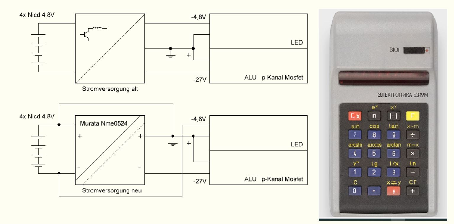
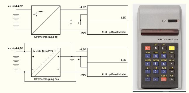
Vergleich Schaltplan Stromversorgung und Foto eines Taschenrechners
4x Nicd 4,8V Stromversorgung alt -4,8V LED -27V ALU p-Kanal Mosfet Murata Nme0524 Stromversorgung neu -4,8V LED -27V ALU p-Kanal Mosfet ЭЛЕКТРОНИКА Б3-19

-
 Bild
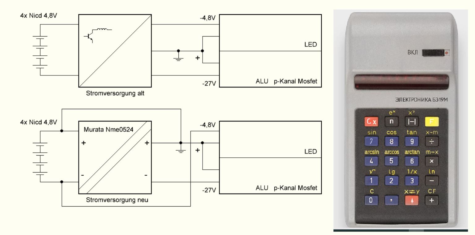
Vergleich alter und neuer Stromversorgung mit Schaltplan und Taschenrechner
4x Nicd 4,8V Stromversorgung alt -4,8V LED -27V ALU p-Kanal Mosfet Murata Nme0524 Stromversorgung neu 4x Nicd 4,8V -4,8V LED -27V ALU p-Kanal Mosfet ЭЛЕКТРОНИКА Б3-19м
-
 Bild
Drei Bände des Werkbuchs Elektronik von Franzis'
-1165 Franzis' Das große Werkbuch Elektronik Band 2 Dioden Thyristoren Triacs Transistoren FETs, MOSFETs Power-MOSFETs Operationsverstärkertechnik Optoelektronik Sensoren Röhrentechnik LWL-Technik Stromversorgung Seiten 1156-2215 Franzis' Das große Werkbuch Elektronik Band 3 Transistor-Schaltungen Operationsverstärkerschaltungen

-
 Bild
Text über MOSFET-Zuverlässigkeit und thermische Entlastung
To improve the reliability of the MOSFET and hence the power supply, the designer could choose to increase the thermal derating of the part. By significantly cooling the part down and setting the working temperature of the MOSFET at 80°C

-
 Bild
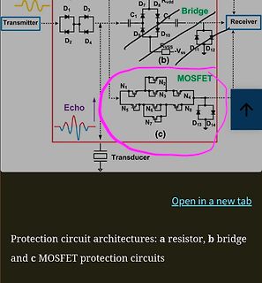
Schaltplan verschiedener Schutzschaltkreis-Architekturen
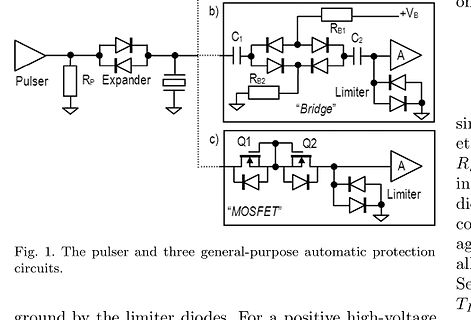
D1 D3 D7 D8 Vdd Receiver D2 D4 C1 C2 D9 D10 Vss D11 D12 Echo N1 N2 N3 N4 N5 N6 N7 N8 D13 D14 (c) MOSFET (b) bridge (a) resistor Transducer Open in a new tab Protection circuit architectures: a resistor, b bridge and c MOSFET protection circuits
-
 Bild
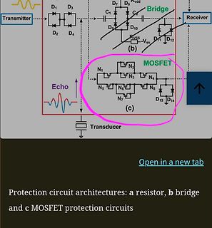
Schaltplan verschiedener Schutzschaltkreis-Architekturen
D1 D3 D7 D8 Vdd Receiver D2 D4 C1 C2 D9 D10 Vss D11 D12 Echo N1 N2 N3 N4 N5 N6 N7 N8 D13 D14 (c) MOSFET (b) bridge (a) resistor Transducer Open in a new tab Protection circuit architectures: a resistor, b bridge and c MOSFET protection circuits
-
 Bild
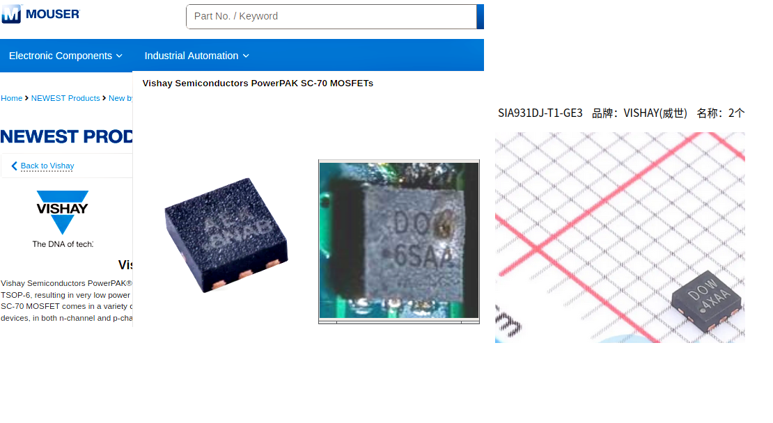
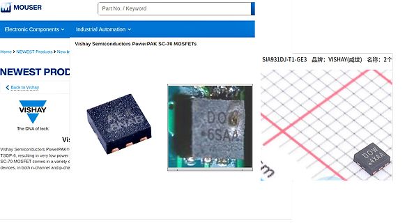
Screenshot einer Mouser-Webseite mit Vishay MOSFET-Produktbildern
Components Industrial Automation Home > NEWEST Products > New b Vishay Semiconductors PowerPAK SC-70 MOSFETs SIA931DJ-T1-GE3 品牌: VISHAY(威世) 名称: 2个 NEWEST PROD Back to Vishay VISHAY The DNA of tech. Vishay Semiconductors PowerPAK TSOP-6, resulting in very low power SC-70 MOSFET comes in a variety devices,
-
 Bild
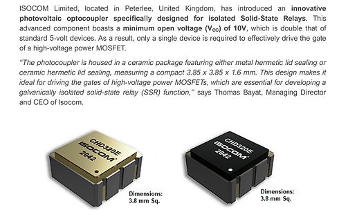
ISOCOM Photocoupler CHD320E Produktpräsentation
a result, only a single device is required to effectively drive the gate of a high-voltage power MOSFET. "The photocoupler is housed in a ceramic package featuring either metal hermetic lid sealing or ceramic hermetic lid sealing, measuring a compact 3.85 x 3.85 x 1.6 mm. This design makes it ideal for driving the gates of high-voltage power MOSFETs, which are essential for developing a galvanically isolated solid-state relay (SSR) function," says Thomas Bayat, Managing Director and CEO of Isocom. CHD320E ISOCOM 2042 Dimensions: 3.8 mm Sq.
-
 Bild
Forenbeitrag über ESP32 und MOSFET-Berechnung
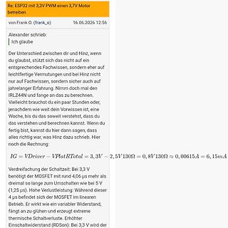
VPlatRTotal = 3,3V - 2,5V 130Ω = 0,8V 130Ω ≈ 0,00615A = 6,15mA Dreidreifung: Bei 3,3 V benötigt der MOSFET mit rund 4,06 µs mehr als dreimal so lange zum Umschalten wie bei 5 V (1,25 µs). Hohe Verlustleistung: Während dieser 4 µs befindet sich der MOSFET im linearen Betrieb. Er wirkt wie ein variabler Widerstand
-
 Bild
Produktbeschreibung von ASFETs für parallele MOSFET-Anwendungen
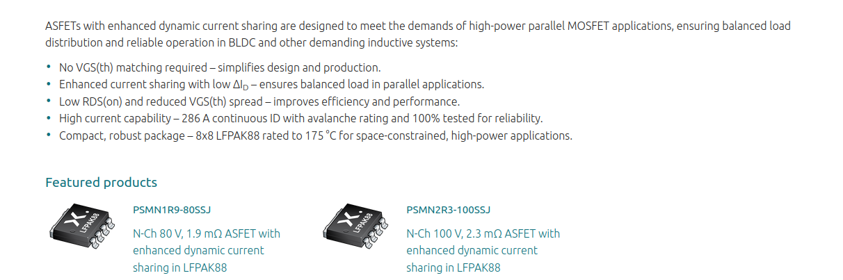
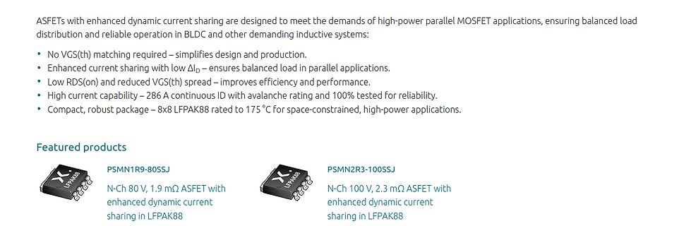
ASFETs with enhanced dynamic current sharing are designed to meet the demands of high-power parallel MOSFET applications, ensuring balanced load distribution and reliable operation in BLDC and other demanding inductive systems: • No VGS(th) matching required – simplifies design and production. • Enhanced
-
 Bild
Schaltplan mit BC547 und P-Kanal MOSFET
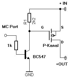
MC Port, 1k, BC547, GND, R1, 2k2, G, S, P-Kanal, D, +IN, +OUT
-
 Bild
Virtueller Aufbau mit Breadboard, Touch Sensor und MOSFET
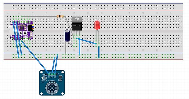
I2C, SDA, SCL, A0, A1, A2, FET P, SIG, VCC, GND, Touch Sensor v1.1
-
 Bild
Schaltplan einer idealen Dioden-OR-Verknüpfung mit MOSFETs
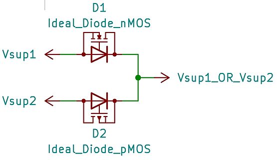
D1 Ideal_Diode_nMOS Vsup1 D2 Ideal_Diode_pMOS Vsup2 Vsup1_OR_Vsup2
-
 Bild
Kennlinien des IRLZ44NPbF MOSFETs
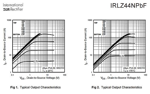
International IOR Rectifier IRLZ44NPbF Fig 1. Typical Output Characteristics ID, Drain-to-Source Current (A) VGS 15V 12V 10V 8.0V 6.0V 4.0V 3.0V 2.5V TOP BOTTOM 0.1 1 10 100 VDS, Drain-to-Source Voltage (V) Fig 2. Typical Output Characteristics 20us PULSE WIDTH TJ = 25°C 20us PULSE WIDTH TJ = 175°C
-
 Bild
Forenbeitrag über ESP32 und MOSFET-Berechnung
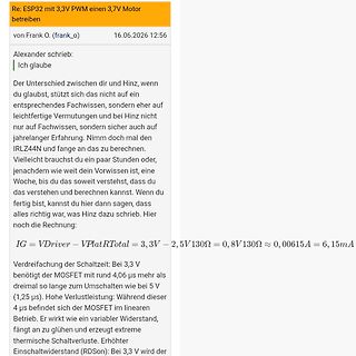
Re: ESP32 mit 3,3V PWM einen 3,7V Motor betreiben von Frank O. (frank_o) 16.06.2026 12:56 Alexander schrieb: Ich glaube Der Unterschied zwischen dir und Hinz, wenn du glaubst, stützt sich nicht auf ein entsprechendes Fachwissen, sondern eher auf leichtfertige Vermutungen und bei Hinz nicht nur auf Fachwissen, sondern sicher auch auf jahrelanger Erfahrung. Nimm doch mal den IRLZ44N und fange an das zu berechnen. Vielleicht brauchst du ein paar Stunden oder, je nachdem wie weit dein Vorwissen ist, eine Woche, bis du das soweit verstehst, dass du das verstehen und berechnen kannst. Wenn du fertig bist, kannst
-
 Bild
Ausschnitt eines Datenblatts für einen P-Channel MOSFET
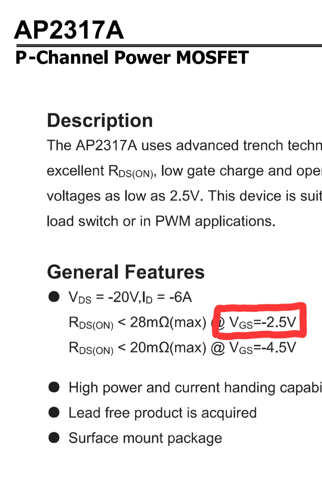
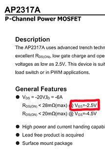
AP2317A P-Channel Power MOSFET Description The AP2317A uses advanced trench techn... excellent RDS(ON), low gate charge and ope... voltages as low as 2.5V. This device is suit... load switch or in PWM applications. General Features
-
Artikel
Pulsweitenmodulation
ansteuernden Rechteckimpulse jedoch dahingehend eine Rolle, dass sie die Verluste der Schaltelemente (MOSFETs) in die Höhe treiben und die ungefilterten Anteile in den Motoren zu Schwingungen führen, weil Resonanzen angeregt werden können. Dimmen von Leuchtmitteln (ohmsch - kapazitiv). Eine spezielle Form
geringer Induktivität sinnvoll sein, die die Anstiege begrenzt. Wie schätze ich die Verlustleistung am MOSFET im PWM Betrieb ab?. Beitrag von Falk: Vereinfacht kann man sagen, dass während der Umschaltzeit die Verlustleistung am MOSFET = 1/4 der Verlustleistung am Verbraucher ist, wenn der eingeschaltet ist
-
Thread
PWM-Sinus-Steller, Sinus-Dimmer 220V AC, 3KW 1 phasig gesucht
wird bei einem PWM Sinussteller die 50-Hz-Netzspannung im Hochfrequenzbereich (kHz-Taktung mittels MOSFET/IGBT) über PWM Logik verarbeitet und über ein integriertes LC-Filter glättet. Kennt jemand einen Schaltplan bzw. fertiges Gerät für: - 220V AC, 3KW, einphasig Aus dem PV Bereich sind mir Fronius
-
Thread
Porsche PCM 3 – Identifikation verbrannter 8-Pin-IC (A1770 M242) + Reboot-Loop
µPA1770, MOSFET von Renesas/NEC. Ersatztyp: DMP2040USD von Diodes.
-
 Bild
Datenblatt und Schaltplan des XC5015 Li-Ion Ladegeräts
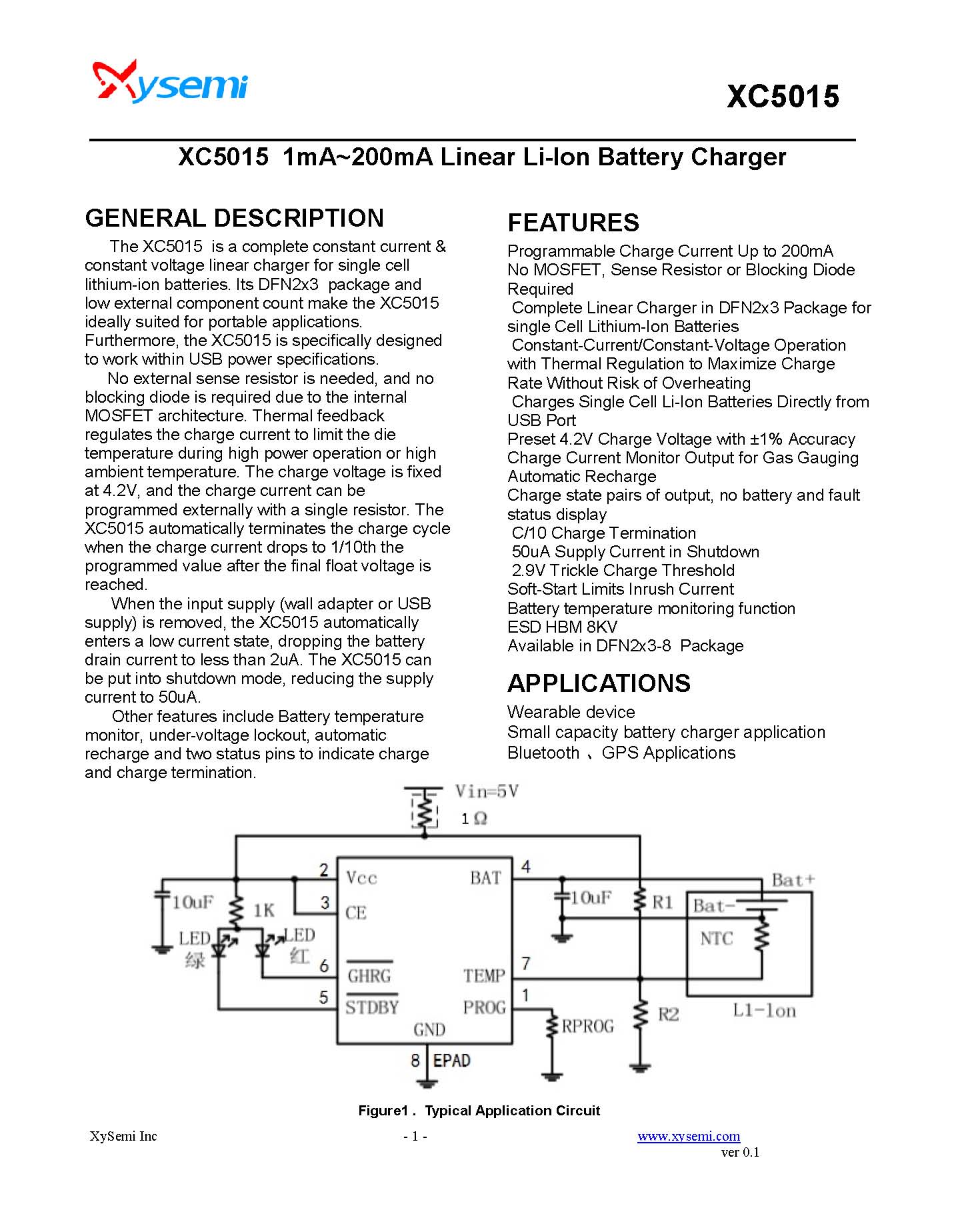
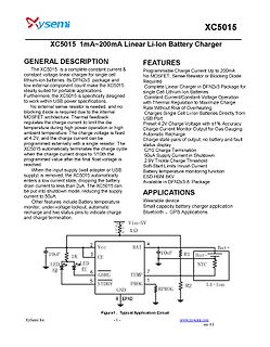
specifications. No external sense resistor is needed, and no blocking diode is required for the MOSFET regulate the charge. Thermal feedback regulates the charge current to limit the temperature during high power charging or high ambient temperature. The charge voltage is fixed at 4.2V, and the charge
-
Thread
ZVS Modul sicher betreiben
de.aliexpress.com/item/1005009437634532.html Es verfügt über Unterspannung, Überstrom, Überhitzung Schutz der Mosfets und einem separaten On/Off switch, der sich auch durch eine Steuerung schalten ließe. Kühlung der Spule erfolgt durch Wasserkühlung. Das Modul wird maximal mit 2.5kW betrieben und dann auch nur
-
Thread
Neue Bauteile: MCX W72, RF-Absicherungsbauteile und intelligentes Hühnerfutter
high-precision stacking technology, the new 1.25kV MLCC addresses these needs, supporting the latest SiC MOSFET technologies. The inherent advantages of C0G in accordance with EIA standards - low loss and stable capacitance over an operating temperature range from -55°C to +125°C - make the new product ideal
-
Thread
Dimmer für Hühner Vogelvoliere für 12V LED-Lichtstreifen mit ext. Zeitschaltuhr Sunset Sunrise Fade
ein PWM-Modulator UC3843AN und ein Dual-OP LM358CN beide im DIL8 Gehäuse mit Sockel, Logiglevel MosFet IRLB3034pbf TO220 (es geht auch jeder andere MosFet, da nur ca. 0,5A geschaltet werden) 3x Elkos THT und einige SMD Widerstände 0805 +THT, Kondensatoren 0805 und Dioden SOD80 DO41. Gezeichnet für Lochrasterplatine
-
Thread
ESP32-E22, schneller Chip aus dem Hause WCH, ressourcensparendes WiFi 7 uvam
Tata Electronics will assemble and test ROHM’s India-designed automotive-grade Nch 100V, 300A Si MOSFET in a TOLL package, targeting mass production shipments by next year. [/c] ### Seeed Studio: LoRA-Karte im MiniPCIe-Format LoRA und LoRAWAN erfreuen sich in den letzten Monaten an permanent wachsender
-
 Bild
MOSFET Trigger Switch Drive Module mit technischen Daten
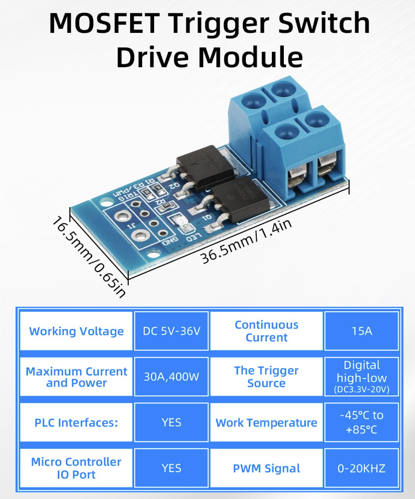
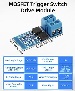
MOSFET Trigger Switch Drive Module 16.5mm/0.65in 36.5mm/1.4in R1 R3 PWM Q2 LED1 LED2 LED3 GND Working Voltage DC 5V-36V Continuous Current 15A Maximum Current and Power 30A,400W The Trigger Source Digital
-
 Bild
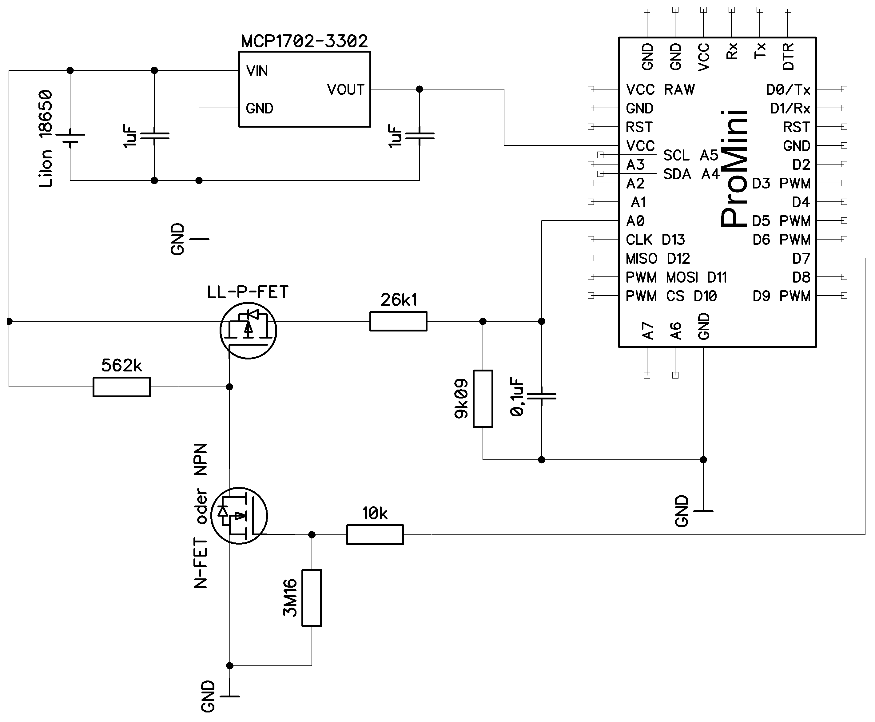
Schaltplan mit Pro Mini, MCP1702-3302 und MOSFETs
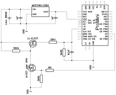
Lilon 18650, 1uF, MCP1702-3302, VIN, VOUT, GND, 1uF, Pro Mini, GND, VCC, RAW, D0/Tx, D1/Rx, RST, GND, D2, D3 PWM, D4, D5 PWM, D6 PWM, D7, D8, D9 PWM, CS, D10, MOSI, D11, MISO, D12, CLK, D13, SDA, A4, A5, SCL, A3, A2, A1, VCC, A0, A7, A6, GND, LL-P-FET, 26k1, 562k, 9k09, 0,1uF, N-FET oder NPN, 10k, 3M16, GND
-
 Bild
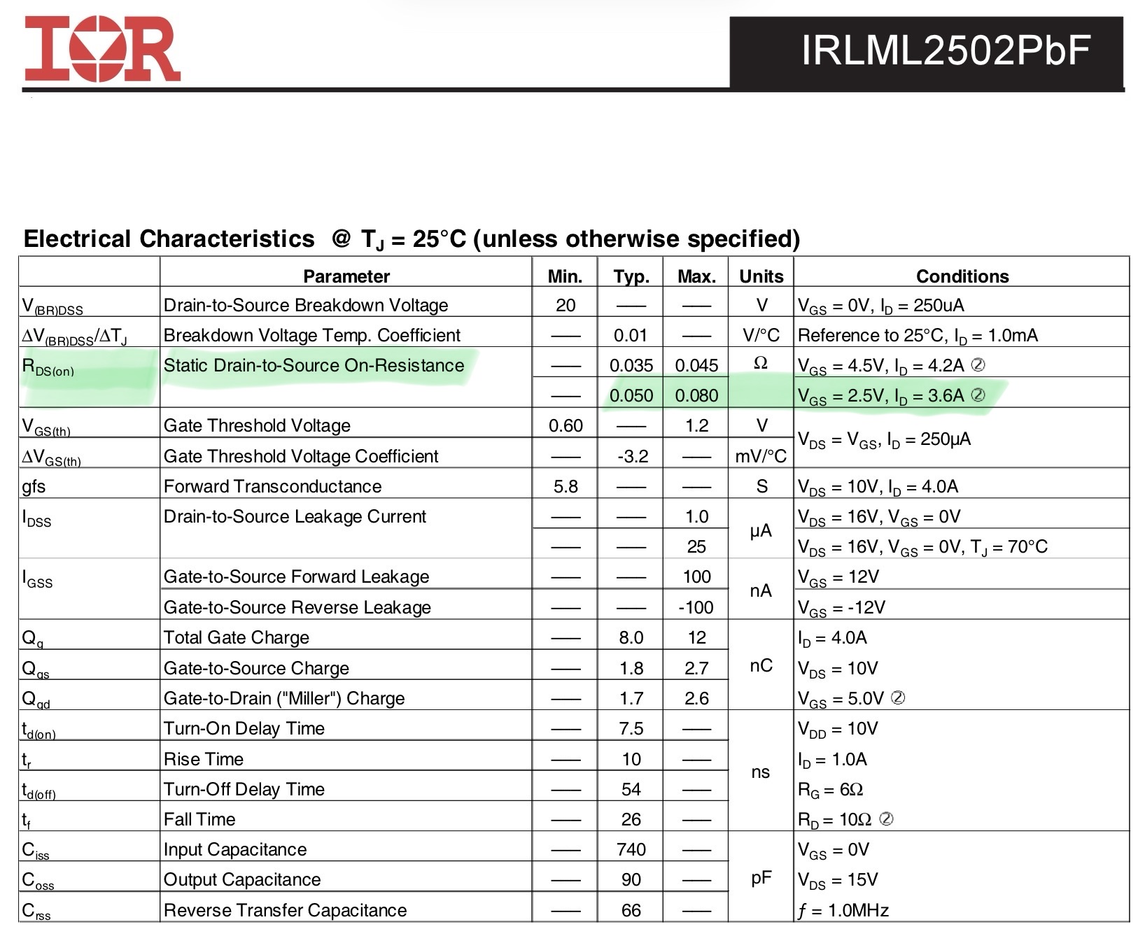
Elektrische Kennwerte eines IRLML2502PbF MOSFETs
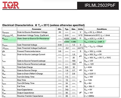
IOR IRLML2502PbF Electrical Characteristics @ TJ = 25°C (unless otherwise specified) Parameter Min. Typ. Max. Units Conditions V|BRDSS Drain-to-Source Breakdown Voltage 20 — — V VGS = 0V, ID = 250uA ΔV|BRDSS/ΔTJ Breakdown Voltage Temp. Coefficient — 0.01 — V/°C Reference to 25°C, RDS(on) Static Drain-to-Source On-Resistance — 0.035 — Ω VGS = 4.5V, ID = 4.2A — 0.050 0.080 VGS = 2.5V, ID = 3.6A gfs Gate Threshold Voltage 0.60 — 1.2 V VGS = VGS, ID = 250uA ΔVGS(th) Gate Threshold Voltage Coefficient — -3.2 — mV/°C Ioss Drain-to-Source Leakage Current — — 1.0 µA VDS = 16V, VGS = 0V I_GSS Gate-to-Source Forward
-
 Bild
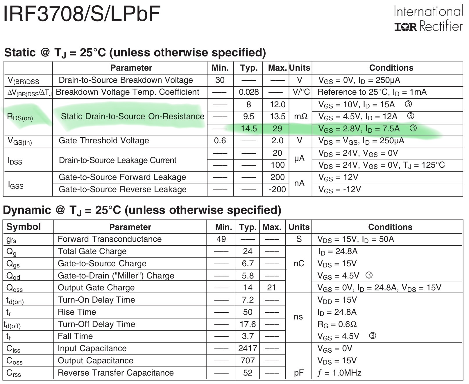
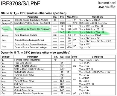
Datenblatt-Tabelle der elektrischen Parameter eines IRF3708 MOSFETs
IRF3708/S/LPbF International IOR Rectifier Static @ TJ = 25°C (unless otherwise specified) Parameter Min. Typ. Max. Units Conditions V(BR)DSS Drain-to-Source Breakdown Voltage 30 V VGS = 0V, ID = 250µA ΔV(BR)DSS/ΔTJ Breakdown Voltage Temp. Coefficient 0.028 V/°C Reference to 25°C, ID = 1mA RDS(on) Static Drain-to-Source On-Resistance 8 9.5 13.5 mΩ VGS = 4.5V, ID = 12A VGS(th) Gate Threshold Voltage 0.6 14.5 2.0 V VGS = VGS, ID = 250µA IDSS Drain-to-Source Leakage Current 20 µA VGS = 24V, VGS = 0V IGSS Gate-to-Source Forward Leakage 100 µA VGS = 24V, VGS = 0V, TJ = 125°C Gate-to-Source Reverse Leakage
-
Artikel
UHF-Modulator ALPS MDLP3W104A
werden (siehe unten). Beim Autor funktioniert aktuell ein Wert von 3k3 an einem ESP8266 über einen "2-MOSFET-Levelshifter" und zeigt ausreichend Abstand zu der Low-Schaltschwelle des ESP als auch eine spezifikationsgemäße Anstiegszeit. Besonderheiten bei 3,3 V-Systemen. Wenn die Ansteuerung von einem Mikrocontroler
erfolgen soll, ist ggf. ein bidirektionaler Pegelwandler ("Levelshifter") erforderlich z.B. mit zwei MOSFETS nach AN97055 von Philips, "Bi-directional level shifter for I2C-bus and other systems". Es sollte überprüft und sichergestellt werden, dass der Low-Pegel auf der 3,3 V-Seite im zulässigen Bereich
-
 Bild
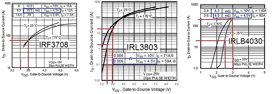
Kennlinien von MOSFETs IRF3708, IRL3803 und IRLB4030
IRF3708, IRL3803, IRLB4030, ID, Drain-to-Source Current (A), VGS, Gate-to-Source Voltage (V), VDS, TJ = 25°C, TJ = 175°C, VGS = 10V, ID = 15A, VGS = 4.5V, ID = 12A, VGS = 2.8V, ID = 7.5A, VDS = 15V, 20us PULSE WIDTH, VGS = 10V, ID = 71A, VGS = 4.5V, ID = 59A, VDS = 25V, 20us PULSE WIDTH, VGS = 10V, ID = 110A, VGS = 4.5V, ID = 92A, VDS = 50V, 60us PULSE WIDTH
-
 Bild
Text über verfügbare Gehäuseoptionen von OptiMOS 3 MOSFETs
Available packages The OptiMOS™ 3 power MOSFET family is available in a wide portfolio of package options to meet all of your design requirements. Packages include PQFN 3.3x3.3, SO-8, SuperSO8 5x6, DPAK, D²PAK, D²PAK-7 pin, TOLL, TOLG, TO-220,

-
 Bild
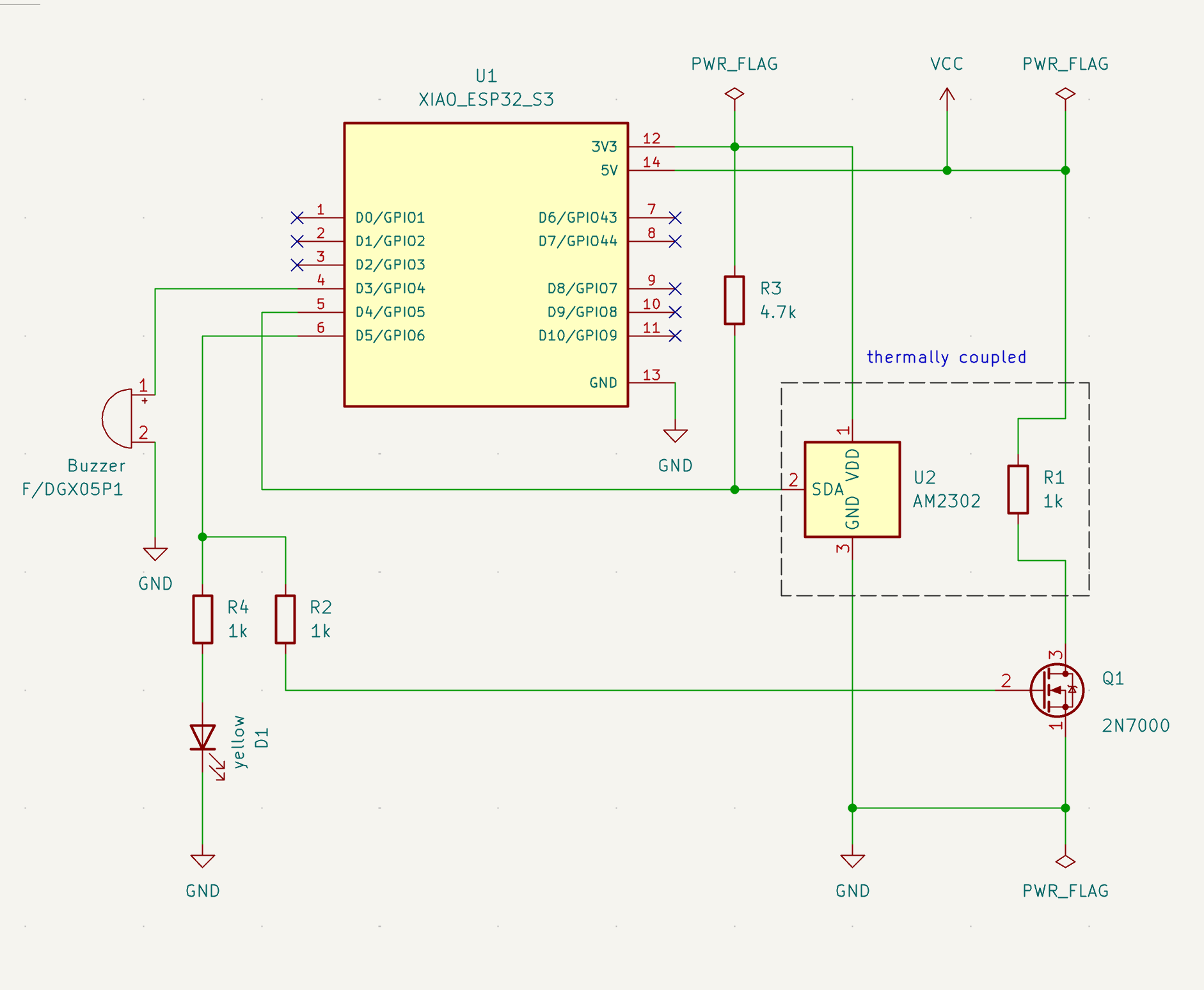
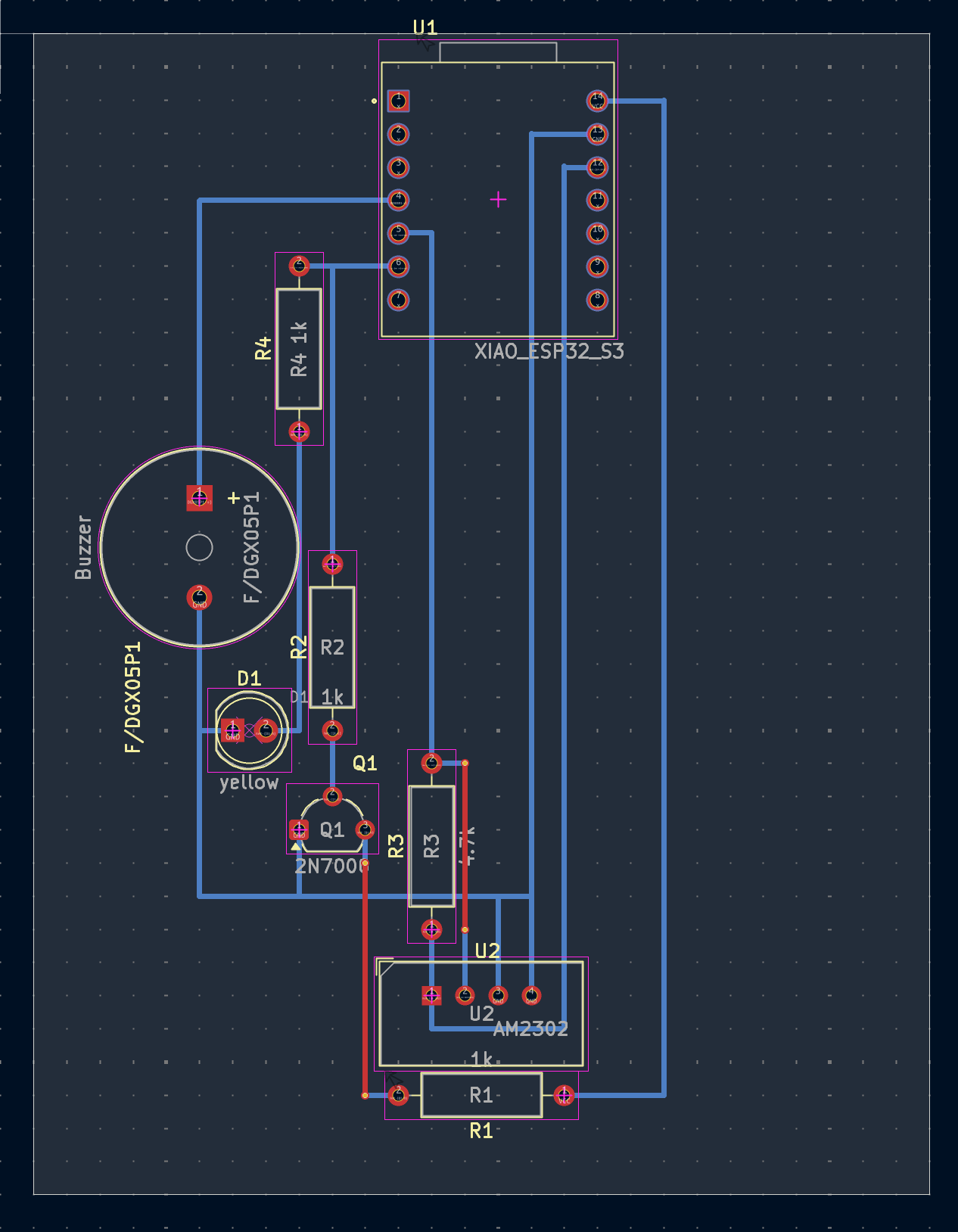
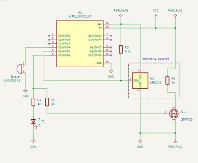
Schaltplan mit XIAO_ESP32_S3, Buzzer und MOSFET
U1 XIAO_ESP32_S3 3V3 5V D0/GPIO1 D1/GPIO2 D2/GPIO3 D3/GPIO4 D4/GPIO5 D5/GPIO6 D6/GPIO43 D7/GPIO44 D8/GPIO7 D9/GPIO8 D10/GPIO9 GND R3 4.7k thermally coupled U2 AM2302 SDA VDD GND R1 1k Q1 2N7000 Buzzer F/DGX05P1 R4 1k R2 1k D1 yellow GND PWR_FLAG
-
 Bild
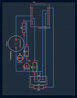
Schaltplan mit XIAO ESP32-S3, Buzzer und MOSFET
U1 XIAO_ESP32_S3 R4 1k Buzzer F/DGX05P1 R2 1k D1 yellow Q1 2N7000 R3 1.1k U2 AM2302 R1
-
Artikel
Wanderkiste (Widlar)
Dennis S. 58xxx 08.06.2024 10.06.2024 02162166000671 Hermes S: CAN Transciever IC/Board, gängige MOSFET für die Bastelkiste, Laser Diode (grün od. blau), immer gern interessante Bauteile (THT/SMD), Retro Computer ICs, Radio-Röhren(E/U Serie) B: Slim DVD SATA Multi Recorder, opt. USB Maus (neu), Steckernetzteile
Hermes 19.5 kg B: div. THT-Bauteile, Oscillator-Block 4MHz S: Analog-Technik Bauteile OP-Amp usw: MOSFET, Relaise; Schaltnetzteile, Step-Down Step-Up Wandler; I2C Bauteile Sensoren Isolatoren; Leiterplatten-Klemmblöcke, Schaltlitze flex. dünn bis 1 mm²; Bücher über AVR und Bussysteme. 15 ENDE Runde VI
-
 Bild
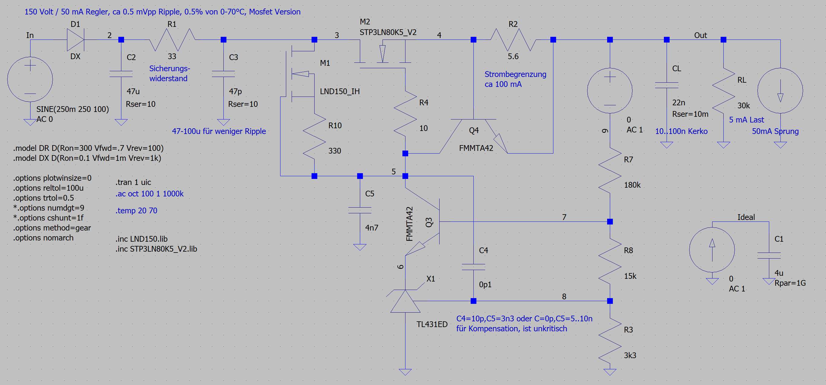
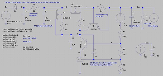
Schaltplan eines Spannungsreglers mit SPICE-Netlist
150 Volt / 50 mA Ripple, ca 0.5% von 0-70°C, Mosfet Version In D1 R1 M2 Out 3 C2 33 C3 4 R2 DX 47u 33 Sichering- widerstand STP3LN80K5_V2 5.6 C3 47p M1 LND150_IH LND150_IH_Rser=10 47-100u für weniger Ripple 47-100u Rser=10 330 R10 10 5 Q4 FMMTA42 4n7
-
 Bild
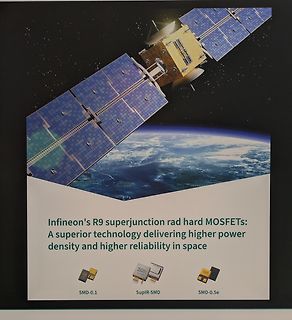
Werbeplakat für Infineon R9 superjunction rad hard MOSFETs
Infineon's R9 superjunction rad hard MOSFETs: A superior technology delivering higher power density and higher reliability in space SMD-0.1 SupIR-SMD SMD-0.5e
-
 Bild
-
 Bild
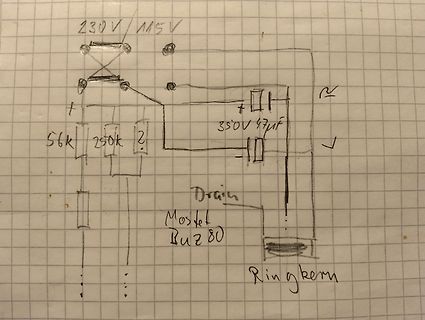
Handgezeichneter Schaltplan eines Schaltnetzteils
230V / 115V 350V 47uF 56k 250k ? Drain Mosfet Buz80 Ringkern
-
 Bild
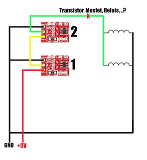
Schaltplan mit zwei Modulen und Induktivitäten
Transistor, Mosfet, Relais, ...? X 2 GND A I/O B VCC 121 1 GND A I/O B VCC 121 GND +5V
-
 Bild
Schaltplan eines Pulser- und Schutzschaltkreises
Pulser RP Expander b) CB RB1 +VB C1 RB2 C2 Limiter "Bridge" A c) Q1 Q2 Limiter A "MOSFET" Fig. 1. The pulser and three general-purpose automatic protection circuits.