-
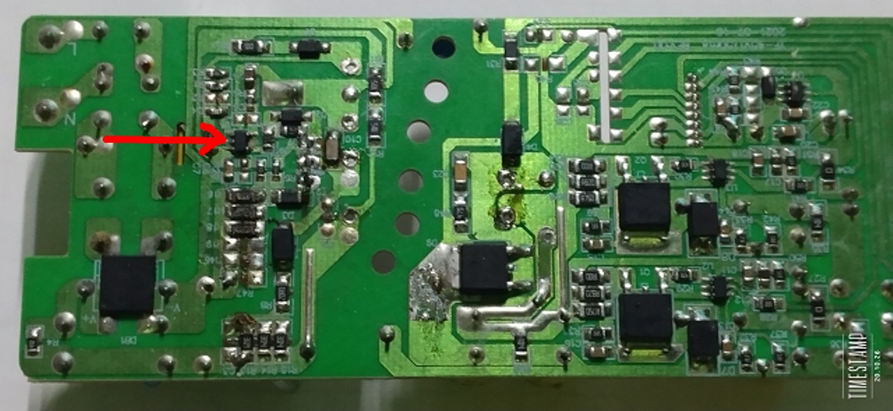
Bild
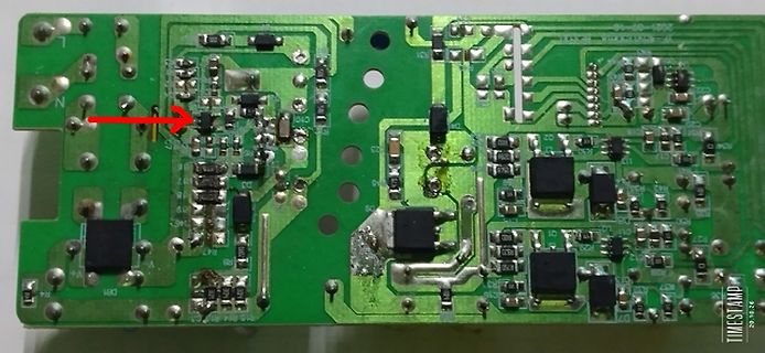
Bestückte grüne Leiterplatte mit rotem Pfeil
L, N, C10, C11, R47, R58, R59, R60, R61, R62, R63, R64, R65, R67, R72, R73, R74, R75, R76, R77, R78, R79, R80, R81, R82, R83, R84, R85, R86, R87, R88, R89, R90, R91, R92, R93, R94, R95, R96, R97, R98,
in „Schaltnetzteil aus LED Deckenleuchte“ · Analoge Elektronik und Schaltungstechnik · · Platinenfotos
-
Datei
Schrittmotor.asm
;R19(H)...R16(L) / R23(H)...R20(L) Rest in R23..R20 ;Soll - Winkel mit einer Kommastelle in R20,R21 mov R4, R20 mov R5, R21 rcall Winkeld ;Nur Berechnung nach - R6,R7 mov R20, R6 mov R21, R7 sub R20, R4 sbc R21, R5
in „Spielerei mit einem 2- und 5-Phasen-Schrittmotor“ · Projekte & Code ·
-
PDF
MP900-SERIES_ENG_TDS.pdf
or a metal clip in contact with the top (2.39 ±.10).DIA(8.12 ±.26) (2.79 ±.26) surface of the part. L + .440 ±.010 Insulation Resistance: 10,000 Megohms min. (11.18 ±.26) The resistor element is electrically isolated from (2.03 ±.51) M0.10Ω (2.92 ±.26) the mounting surface. Figure 1 1% TO-126 Style .053
in „Suchstrategie Isolierter NPN Leistungstransistor“ · Analoge Elektronik und Schaltungstechnik ·
-
PDF
Gralab_300_sch.pdf
BUZZER M1 N/A N/A B MOTOR AC 4RPM B HAYDON 22A1 P10 SAFELIGHT ENLARGER OUT 2 ENLARGER OUT 1 (120VAC 60 Hz) L:\01_GJO_PROJ\ACTIVE_PRJ\2026\26001_Gralab_Timer\PCB_Design\26001_Gralab 300\26001_Gralab 300.Ddb - Gralab_300\Gralab 300.sch PCB Name: N/A Title Unless otherwise specified, all values are as follows
-
Bild
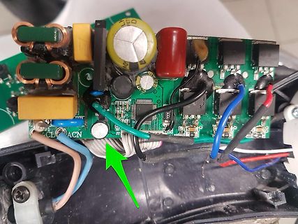
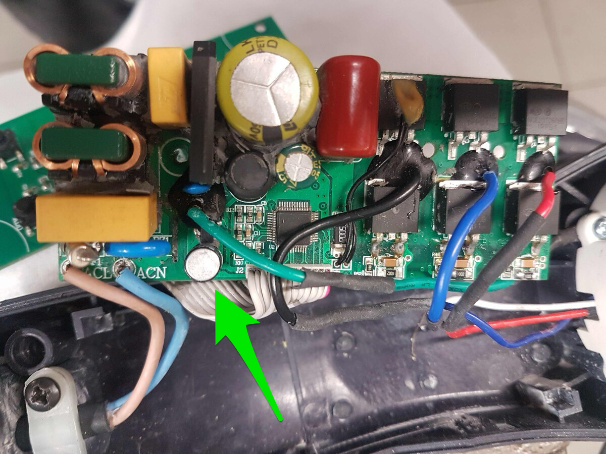
Nahaufnahme einer Leiterplatte mit elektronischen Bauteilen
L, N, R1, R2, R3, R4, R5, R6, R7, R8, R9, R10, C1, C2, C3, C4, C5, C6, C7, C8, C9, C10, C11, C12, C13, C14, C15, C16, C17, C18, C19, C20, C21, C22, C23, C24, C25, C26, C27, C28, C29, C30, C31, C32, C33
in „321VDC an Brueckengleichrichter“ · Analoge Elektronik und Schaltungstechnik · · Platinenfotos
-
Bild
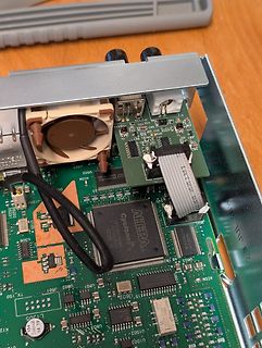
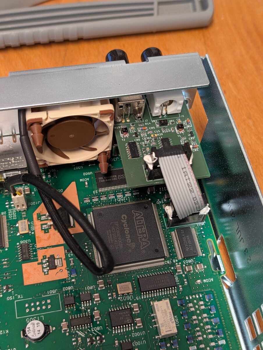
Detailaufnahme einer Leiterplatte mit Altera Cyclone FPGA
Cyclone II EP2C16F208C8, U307, U502, U102, U1003, U062, U063, U061, U021, U022, U051, U052, U060, L305, R12, C15, C16, C17, C18, C19, C20, C21, C22, C23, C24, C25, C26, C27, C28, C29, C30, C31, C32, C33, C34, C35, C36, C37, C38, C39, C40, C41, C42, C43, C44, C45, C46, C47, C48, C49, C50, C51, C52, C53, C54, C55, C56, C57, C58, C59, C60, C61, C62, C63, C64, C65, C66, C67, C68, C69, C70, C71, C72, C73, C74, C75, C76, C77, C78, C79, C80, C81, C82, C83, C84, C85, C86, C87, C88, C89, C90, C91, C92, C93, C94, C95, C96, C97, C98, C99, C100
in „[V] Keysight 33220a Funktionsgenerator“ · Markt · · Platinenfotos
-
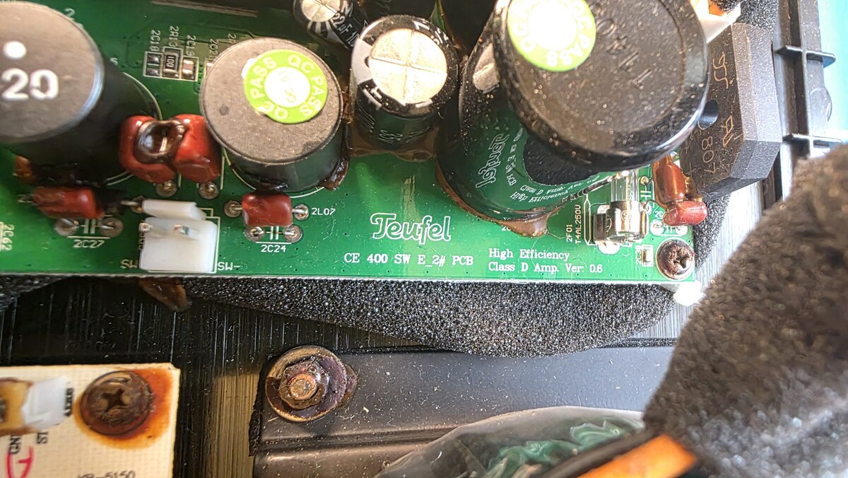
Bild
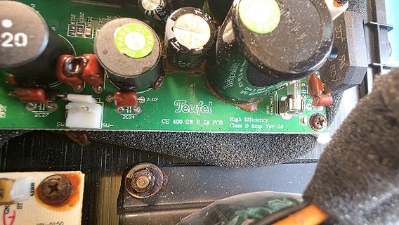
Nahaufnahme einer Leiterplatte mit Elektrolytkondensatoren
20, 2C9, 2C1, 2C27, 2C24, 2L07, Teufel, CE 400 SW E 2# PCB, High Efficiency Class D Amp. Ver: 0.6, 2C42, 2C10, 2C11, 2C12, 2C13, 2C14, 2C15, 2C16, 2C17, 2C18, 2C19, 2C20, 2C21, 2C22, 2C23, 2C25, 2C26, 2C28, 2C29, 2C30, 2C31, 2C32
in „Teufel US 2110/1 SW - Kondensator Kapazität gesucht“ · Analoge Elektronik und Schaltungstechnik · · Platinenfotos
-
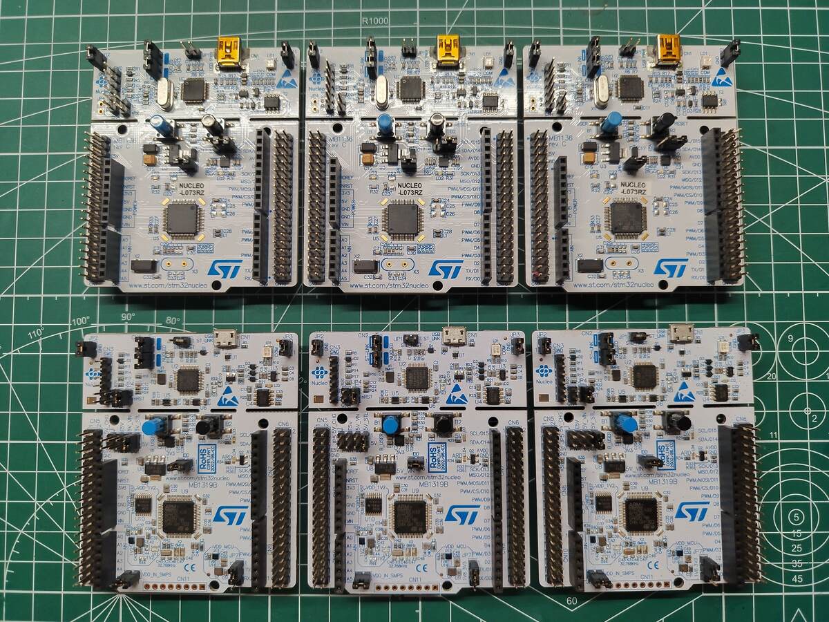
Bild
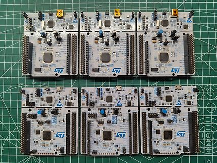
Mehrere ST Nucleo-L073RZ Mikrocontroller-Boards
NUCLEO-L073RZ, STM32, www.st.com/stm32nucleo, MB11319B, PWM/MOS/D1, PWM/D2, PWM/D3, PWM/D4, PWM/D5, PWM/D6, PWM/D7, PWM/D8, PWM/D9, PWM/D10, PWM/D11, PWM/D12, PWM/D13, PWM/D14, PWM/D15, PWM/D16, PWM/D17, PWM/
in „[V] Diverse STM32 Nucleo Boards“ · Markt · · Platinenfotos
-
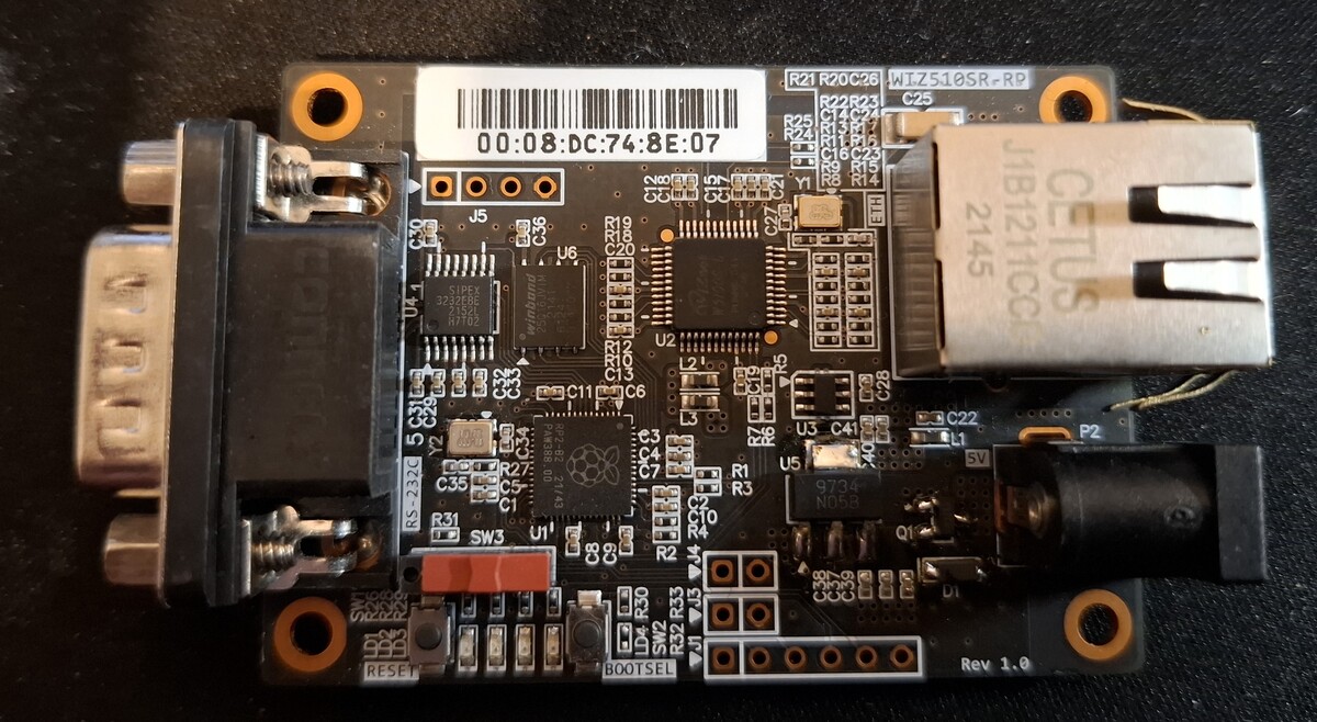
Bild
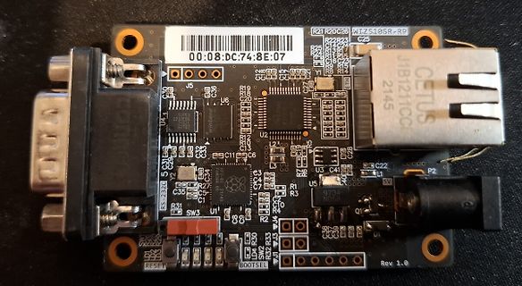
USB-zu-RS232-Adapterplatine mit D-Sub-Anschluss
C34 C35 C37 C38 C39 C40 C41 C42 C43 C44 C45 C46 C47 C48 C49 C50 C51 C52 C53 C54 C55 C56 C57 C58 C59 C60 C61 C62 C63 C64 C65 C66 C67 C68 C69 C70 C71 C72 C73 C74 C75 C76 C77 C78 C79 C80 C81 C82 C83 C84 C85 C86 C87 C88 C89 C90 C91 C92 C93 C94 C95 C96 C97 C98 C99 C100 RS-232C Y2 R27 R26 R25 R24 R23 R22 R21 R20 R19 R18 R17 R16 R15 R14 R13 R12 R11 R10 R9 R8 R7 R6 R5 R4 R3 R2 R1 SW3 P2 5V L1 9734 N058 RESET BOOTSEL Rev 1.0
in „[V] 3 verschiedene WIZnet serial to Ethernet module mit RasPi (25€)“ · Markt · · Platinenfotos
-
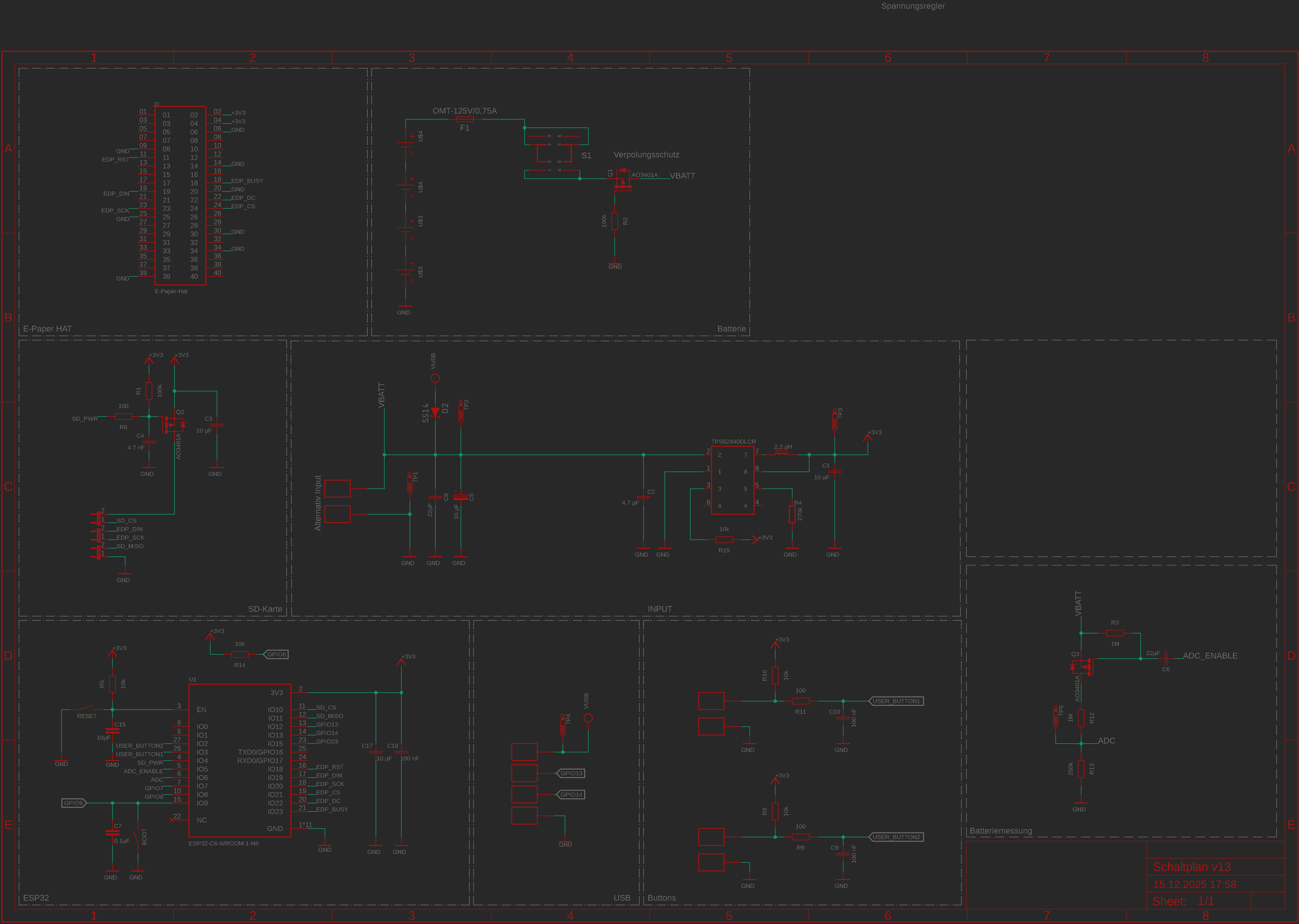
Bild
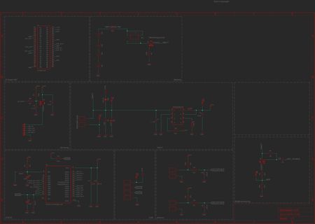
Schaltplan eines ESP32-basierten Systems mit Batterie und SD-Karte
OMT-L25HS 75A, F1, S1, Verpolungsschutz, VBATT, GND, E-Paper HAT, ESP_RST, ESP_CS, ESP_D1, ESP_D2, ESP_D3, ESP_D4, ESP_D5, ESP_D6, ESP_D7, ESP_D8, ESP_D9, ESP_D10, ESP_D11, ESP_D12, ESP_D13, ESP_D14, ESP_D15
in „E-Paper Schaltplan“ · Mikrocontroller und Digitale Elektronik · · Schaltpläne
-
PDF
EMRFD_Abstract.pdf
section begins with a discussion of the directional nature of impedance in a circuit. The classic L, pi, and Tee networks are discussed with included design equations. Transmission lines then provide impedance matching, followed by ideal transformers using power iron and ferrite cores. The ferrite
in „Wie wird ein TO-50-Transistor auf einem Steckbrett angebracht?“ · Analoge Elektronik und Schaltungstechnik ·
-
Bild
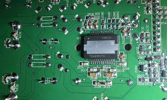
Nahaufnahme einer bestückten Leiterplatte mit TDA8950TH
2C49 2C44 2C48 59 2R18 2C10 2R27 2R05 2R03 2C09 2R04 2C65 2R01 2C69 2C67 2L9 2C70 2C71 2R03 2C02 2R02 2C11 2Q03 2R32 2Q02 2C05 2C16 2R07 2R10 2R08 2C15 2C06 2C07 2C08 2C17 2C14 2C12 2C13 2R21 2C35 2R20 2C34 TDA8950TH 2IC04 2IC02 2IC03 2IC05 2IC06 2IC07 2IC08 2IC09 2IC10 2IC11
in „Teufel US 2110/1 SW - Kondensator Kapazität gesucht“ · Analoge Elektronik und Schaltungstechnik · · Platinenfotos
-
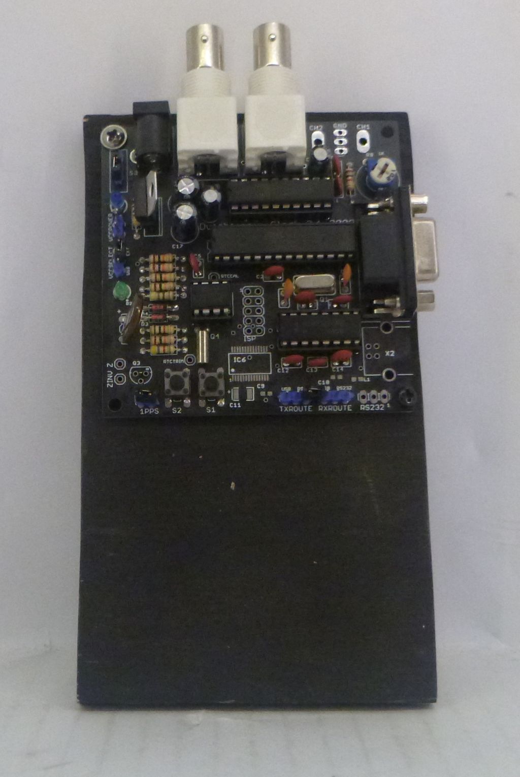
Bild
Leiterplatte mit Anschlüssen und Bauteilen
CH2 GND CH1 C1 L1 C2 C3 C4 C5 C6 C7 C8 C9 C10 C11 C12 C13 C14 C15 C16 C17 C18 C19 C20 C21 C22 C23 C24 C25 C26 C27 C28 C29 C30 C31 C32 C33 C34 C35 C36 C37 C38 C39 C40 C41 C42 C43 C44 C45 C46 C47 C48 C49 C50 C51 C52 C53 C54 C55 C56 C57 C58 C59 C60 C61 C62 C63 C64 C65 C66 C67 C68 C69 C70 C71 C72 C73 C74 C75 C76 C77 C78 C79 C80 C81 C82 C83 C84 C85 C86 C87 C88 C89 C90 C91 C92 C93 C94 C95 C96 C97 C98 C99 C100 C101 C102 C103 C104 C105 C106 C107 C108
in „[V] Platine für Uhrenanzeige für analoge Oszilloskope“ · Markt · · Platinenfotos
-
Datei
Schrittmotor.asm
;R19(H)...R16(L) / R23(H)...R20(L) Rest in R23..R20 ;Soll - Winkel mit einer Kommastelle in R20,R21 mov R4, R20 mov R5, R21 rcall Winkeld ;Nur Berechnung nach - R6,R7 mov R20, R6 mov R21, R7 sub R20, R4 sbc R21, R5
in „Spielerei mit einem 2- und 5-Phasen-Schrittmotor“ · Projekte & Code ·
-
Datei
t13-charlieplexing.asm
Fotodiode A o--|PB4 PB1|--o 470R -- LEDKette-Pin2 ; Fotodiode K o--|GND PB0|--o 470R -- LEDKette-Pin3 ; L_________/ ; ; ; ********************************** ; P O R T S A N D P I N S ; ********************************** ; ; (Add symbols for all ports and port pins with ".equ" here) ; (e.g. .equ pDirD = DDRB
in „Attiny13a stürzt ab“ · Mikrocontroller und Digitale Elektronik ·
-
PDF
Sonos_Play_One.pdf
+24V F301 8 2AT SMBJ110A 7 1 1 D301 6 R301 R302 X1-2 R? 1 L1 2 A BR301 4 20R 20R C1 C2 - + +C358 D303 5 X1-1 MOV 3 4 S1M + C337 +C33? C332 C547 0.47u 0.47u 2 100u/400V TR1 A T? I R?. GNDI 100nF 10uF SPD03N60C3BTMA1N C361 2n2 D302 I SCK-052 5R 2A GNDI S320 R321
in „Sonos Play 1: FAN6751“ · Analoge Elektronik und Schaltungstechnik ·
-
PDF
Datasheet_MFRC522.pdf
l b (1) Reserved. n 2 c d 1 o Fig 10. UART write data timing diagram a 6 g d d p l Remark: The data byte can be sent directly after the address byte on pin RX. e m f s o . Address byte: The address byte
in „IRQ am RFID RC522“ · Mikrocontroller und Digitale Elektronik ·
-
Artikel
CAN
Chip (SBC) TSSOP 32-Pin Serial Interface (SPI) Spannungsregler 3.3 V oder 5.0 V (LDO) 6kV ESD Schutz L4969. ST Microelectronics System Base Chip (SBC) SO20 Serial Interface (SPI) Spannungsregler (LDO) MC33889. Motorola Freescale System Base Chip (SBC) SO28 Serial Interface (SPI) Spannungsregler (LDO)
mehr her! Es ist auch "nichts" mehr am Markt beschaffbar, wenn, dann zu horrenden Preisen (um die 60,-EUR/Stück zur Zeit). --Patrick 09:08, 25. Jan 2005 (CET) obsolete DS 36001M. Obsolete MCP2502X/5X. CAN-IO Erweiterung. Braucht praktisch nur noch Quarz und Transciever. Preise ab 3€ bis zu 8 digitale
Artikel ·
-
PDF
CA-C03.pdf
Antennafeeder 2. Feeder identificationmark 3. Antenna welding fixed end Size Three View symbol Size(mm) L 5.5±0.1 w 2.0±0.1 T 1.0±0.1 a 0.5±0.1 2 CA-C03_V01 CA-C03 Specifications Electrical Characteristics CA-C03 Specification Working Frequency 2450±50MHz Initial frequency band(GHz) 2.7GHz Band Width >100MHz
in „ESP32-C6 Mini auf externe Antenne umrüsten“ · Mikrocontroller und Digitale Elektronik ·
-
Thread
Softwareupdates, Mikrocontroller und Neues von Arduino und Raspberry Pi
22500 für den TNID-Wert (bis zu 3 x 10¹¹ p/cm²) und ESCC 25100 für Single-Event Burnout (SEB, bis zu 60 MeV/cm²/mg). Die drei Bauelemente sind bereits in die Produktion gegangen. Die Preise betragen 3,- US-Dollar für die Version LEO1N5819AF, 5,- US-Dollar für die LEO1N5822AF und 4,50 US-Dollar für die
storage, and an ultra-compact 1.9 by 2.3 mm chip-scale package, the smallest available in the nRF54L Series. . . . Uniquely, the nRF54LV10A is also the world’s first Bluetooth LE SoC to combine low voltage with Bluetooth Channel Sounding support. – via https://www.nordicsemi.com/Nordic-news/2025/
Mikrocontroller und Digitale Elektronik ·Tam H. · ·0 Antworten
-
Artikel
Transformatoren und Spulen
keine Umrechnung nötig ist. Die Grundeigenschaft einer jeden Spule ist Induktivität , Formelzeichen L. Sie ist gemessen in Henry, geschrieben als H, definiert durch: oder in Worten: Ein Henry ist die Induktivität, welche den Strom um 1 Ampere steigen läßt, wenn man für eine Sekunde ein Volt anlegt. Diese
Einheit Einheit Kurzform magnetischer Fluß Weber Wb magnetische Flußdichte B Tesla T Induktivität L Henry H Spannung U Volt V Strom I Ampere A Fläche A Quadratmeter m² Zeit t Sekunde s Energie E Joule J Windungszahl N keine 1 Frequenz f Hertz Hz Länge l Meter m Widerstand R Ohm Ω spezifischer Widerstand
Artikel ·
-
PDF
S32K-RM.pdf
Register Offset FTMOPT0 Ch 11.3.1.3.2 Diagram Bits 31 30 29 28 27 26 25 24 23 22 21 20 19 18 17 16 R L L L L L L L L E E E E E E E E K K K K K K K K L L L L L L L L W 3 2 1 0 7 6 5 4 M M M M M M M M F F F F F F F F Reset 0 0 0 0 0 0 0 0 0 0 0 0 0 0 0 0 Bits 15 14 13 12 11 10 9 8 7 6 5 4 3 2 1 0 R L L
-
PDF
Components_alphabetic_order.pdf
resistance of coil 1 R2·i2 = j·2π·f · (L2·i2 + R2 0 series resistance of coil 2 k12·√L1·√L2·i1 + k23·√L2·√L3·i3) + R2·i2 R3 0 series resistance of coil 3 v3 = L3 · di3/dt + k13·√L1·√L3 · di1/dt + k23·√L2·√L3 · di2/dt + R3·i3 = j·2π·f · (L3·
-
PDF
mega3_06.pdf
I0FC4 61–62 Include Files9 I0FC0M – I0FC4M 55–56 include file9 I0IC 61, 63 Inner Screen Display Word60 I0ICM 55, 57 Inner screen display wor80 I0TRB 61–62 inner screen display wor60 I0TRBM 55–56 INNER SCREEN DISPLAY WORD 0 60–62 I0TRF 61–62 INNER SCREEN DISPLAY WORD 1 63–65 I0TRFM 55–56 Inner screen mask
in „Vollständiges Datenblatt über SDA 5273 gesucht“ · Mikrocontroller und Digitale Elektronik ·
-
Datei
main.cpp
50000; // 50 ms // Aggregation interval in seconds static const uint32_t AGGREGATION_INTERVAL_S = 60; // Data-log file on LittleFS static const char *DATA_FILE = "/pendulum_log.csv"; // Maximum entries kept in RAM ring buffer (also max served via API) static const size_t MAX_ENTRIES = 1000; // Environment
in „Datenlogger Pendeluhr“ · Mikrocontroller und Digitale Elektronik ·
-
PDF
W5500_ds_v110e.pdf
..59 5.4 Power Dissipation ........................................................................60 5.5 AC Characteristics........................................................................60 5.5.1 Reset Timing ........................................................................60 5.5.2 Wake
in „Schaltung W5500“ · Mikrocontroller und Digitale Elektronik ·
-
PDF
DATASHEET_CRF_SERIES-2.pdf
oC - 55 ... 350 Thermal resistance KW -1 125 100 85 65 65 48 Failure rate -9 -1 (Total, o , max., 60% conf. lev.) 10 * h appr. 10, depends on value Endurance o DR (P70 70 C, 1000) [R] % ± 5,0 average Damp heat, steady state DR (40 C, 93% r.h., 56d) [R] % ± 5,0 DR Climatic sequence [R] % ± 2,0 Terminal
in „Sicherungswiderstand: Datenblatt Verständnis Problem“ · Analoge Elektronik und Schaltungstechnik ·
-
PDF
DC-Motor_31x51__1.13.021.3XX.pdf
Läuferträgheitsmoment J gcm 16 16 Terminal resistance Anschlusswiderstand R Ohm 4.4 16 Inductance Induktivität L mH 6.2 13 Mech. time constant Mech. Zeitkonstante τ ms 11 11 m Electr. time constant Elektr. Zeitkonstante τe ms 1.4 0.75 Speed regulation constant Drehzahregelkonstante R m rpm/Ncm 680 640 Torque constant
-
Artikel
8bit-CPU: bo8
B.AS O.KZ O.KS B.KZ B.KS 50- O.WY O.RP B.WY B.CN GTR ADR GTA NOL 58- IKL DKL IXL DXL IYL DYL IZL DZL 60- AD. LV. AV. SV. GT. AN. XR. NR. 68- STMX LVMX AVMX SVMX GTMX ANMX XRMX NRMX 70- STMY LVMY AVMY SVMY GTMY ANMY XRMY NRMY 78- STMZ LVMZ AVMZ SVMZ GTMZ ANMZ XRMZ NRMZ 80- NO2 TK1 TK2 TK3 TK4 TK5 TK6 TK7
wird s Bitstellen nach oben verdreht I%s mit s= 0..7 % B D%E % B IKL nn K <= K+nn DKL nn K <= K-nn I%L nn % <= %+nn+1 D%L nn % <= %-nn-1 GTA nn K 0 NOL 00 K <= R 2 Zyklen GT.Q K <= Q S.RP R <= P+1 O.RP nn R <= P+2 P <= P+nn+3 Bedingung cc ist WY always VZ V ist 0 VS V ist nicht 0 UZ U ist 0 US U ist nicht
Artikel ·
-
Datei
dds-orig.asm
ldi tBCD1,0x9f ; initialize digits 3 and 2 binBCD_3: subi tBCD1,0x10 subi fbinL,low(-1000) ; subiw fbin,1000 sbci fbinH,high(-1000) brcs binBCD_3 binBCD_2: inc tBCD1 subi fbinL,low(100) ; subiw fbin,100 sbci fbinH,high(100) brcc binBCD_2 ldi tBCD0,0xa0 ; initialize digits 1 and 0 binBCD_1: subi tBCD0,0x10 subi fbinL,-10 ; subiw fbin,10 brcs binBCD_1 add tBCD0,fbinL binBCD_ret: ret Bin4BCD: rcall Bin2BCD20 clr tBCD3 ; initial highest bytes of result ldi tBCD4,0xfe binBCD_loop: subi tBCD0,-0x33 ; add 0x33 to digit
in „Claude Code trifft AVR-Assembler: vom Chip in den Browser mit einem Prompt“ · Mikrocontroller und Digitale Elektronik ·
-
PDF
AM700_SM.pdf
BCompensation FrequencyAdjust R340 A MSB R252 B MSB R245 Digital Audio Board A3 Generator PLL Freq Adjustment L1 Frequency Offset Frequency Adjustment L5 Frequency Offset Frequency Adjustment L7 Eye Sampler Frequency Adjustment L16 GeneratorLevel R483 GeneratorBoard A5 A DAC Gain (Left) R24 B DAC Gain (Right)
in „Tektronix AM700“ · Mikrocontroller und Digitale Elektronik ·
-
PDF
40146F.pdf
Kuala Lumpur Tel: 34-91-708-08-90 Fax: 630-285-0075 Tel: 86-571-2819-3180 Fax: 34-91-708-08-91 Tel: 60-3-6201-9857 Cleveland Fax: 86-571-2819-3189 Fax: 60-3-6201-9859 UK - Wokingham Independence, OH China - Hong Kong SAR Tel: 44-118-921-5869 Tel: 216-447-0464 Malaysia - Penang Fax: 44-118-921-5820 Tel: 852-2401-1200 Tel: 60-4-227-8870 Fax: 216-447-0643 Fax: 852-2401-3431 Fax: 60-4-227-4068 Dallas China - Nanjing Addison, TX Philippines - Manila Tel: 972-818-7423 Tel: 86-25-8473-2460 Tel: 63-2-634-9065 Fax: 86-25-8473-2470
in „Fehlersuche Funksender Zentralverriegelung Toyota Yaris“ · Fahrzeugelektronik ·
-
PDF
PCA9532.pdf
L L L L L Transparent top view Fig 4. Pin configuration for HVQFN24 PCA9532 All information provided in this document is subject to © NXP Semiconductors N.V. 2016. All rights reserved. Product data sheet
in „[V] 10St. SMD 16-bit LED I2C Treiber NXP_PCA9532PW.112 (TSSOP24) (10€)“ · Markt ·
-
PDF
FA-Bauteiletester_BX-232_Bauanleitung.pdf
Fichten-Fieldday des OV Lennestadt O28 Spannungsquelle und ein passendes Stan- – geregelter Lötkolben 60…80 W mit desDARCe.V.undgehtaufdenvonKarl- dardkabel. Die entsprechende Schaltung dünner Bleistiftlötspitze sowie Lötzinn Heinz Kübbeler [2] gründlich überarbeite- zur Überwachung und Steuerung des La
in „Funkamateur Bauteiletester BT2 BX232 Wer kann mir helfen?“ · PC Hard- und Software ·
-
Artikel
AVR Arithmetik
detaillierte Ausführungen zur 8-Bit-Arithmetik auf AVR gibt es eine Seite im AVR-Tutorial. Glossar. LSB: L east S ignificant B yte, niedrigstwertiges Byte MSB: M ost S ignificant B yte, höchstwertiges Byte Vergleich. 16 Bit. 32 Bit. Addition. 16 Bit + 16 Bit. 32 Bit + 32 Bit. Subtraktion. 16 Bit - 16 Bit.
sqrtu32_floor sqrtu64_floor sowie die sqrt Funktionen in . + Ressourcen-Verbrauch, Abrunden Flash 60 Bytes RAM 2 3 Bytes dynamisch, 0 Bytes statisch Laufzeit 260 300 Ticks (inclusive Zeiten für CALL+RET) sqrt32.S (sqrt32_floor) avr-gcc-Implementierung (16 Bit). Falls eine MUL-Instruktion vorhanden ist
Artikel ·
-
PDF
ABB_Terra_53.pdf
Option: CHAdeMO Input AC power connection 3P + N + PE Input voltage range 400 V AC+/-10% (50 Hz or 60 Hz) N Max. rated input current & power 125A, 86 kVA F 1 Power factor (full load) > 0.96 3 0 Efficiency 95% at nominal output power 2 DC output V 4 Maximum output power 50 kW d r Output voltage range
in „Ladezustand Elektroauto (Typ2 Ladung)“ · Fahrzeugelektronik ·
-
PDF
DabrowskiBuschStelzer-Radar.pdf
2 3 4 5 6 7 01 00 00 00 00 20 00 02 Frame Header ns ss 9 18 02 73 0B 00 44 0D 0E Scanline Header > l st rc 1D 07 34 92 0C 00 00 01 a scale = 00 44 59 13 00 40 00 CB ▯ 32 u1 u2 > Scanline 512 polar pixels in 8 bit grayscale . ; ns Number of scan lines, always 32d (untested) ss Size of scan line, always 512d (untested) l length of scan line header, always 24d (untested) st unknown, probably status: 02 valid data; 18 spin up rc raw scan line counter 0..4095 a absolute angle of scan line 0::4095 = 0::360 scale scan radius
in „Platinenfotos: Navico 3G Schiffsradar“ · HF, Funk und Felder ·
-
PDF
NODEMCU_DEVKIT_V1_0.PDF
ORGANIZATION GND NODE MCU TEAM D D WEBSITE WWW.NODEMCU.COM 1 2 3 4 1 2 3 4 USB TO UART A GND R6RPIR60PIR602 RXD0 A AUTO PROGRAM CIRCUIT TXDX0 DTR RTS RST GPIO0 1 1 1 1 D R R S S 1 0 0 1 G D D R C 0 1 1 0 9 8 7 6 5 4 3 2 U2U 2 2 2 2 2 2 2 2CP2102 D R S D DT T C G D D TRXR C N DCDC P I U 2DCD1 NCP I U
in „NodmCU ESP8266 nicht zu flashen“ · Mikrocontroller und Digitale Elektronik ·
-
Datei
RTX5060_8GB_100mAutoTanken.txt
0.02 - 0.03 liters of gas (very rough estimate, maybe less). * *Cost:* At 1.80€/L, that's roughly 5-10 cents. * *Walking cost:* Calories burned (negligible cost to body). * **The "Chicken and Egg" Problem:** What if the tank is *completely* empty? You can't drive. You have to walk
in „Neues Unterforum für KI-Themen einrichten ?“ · www.mikrocontroller.net ·
-
PDF
Inverse_voltage-MC34063ACD-STMicroelectronics.pdf
5.00 0.189 0.197 E 3.80 4.00 0.150 0.157 e 1.27 0.050 H 5.80 6.20 0.228 0.244 h 0.25 0.50 0.010 0.020 L 0.40 1.27 0.016 0.050 k 8° (max.) ddd 0.1 0.04 0016023/C 20/23 DocID5257 Rev 12 MC34063AB, MC34063AC, MC34063EB, MC34063EC Package mechanical data Tape & reel SO-8 mechanical data mm. inch. Dim. Min. Typ. Max. Min. Typ. Max. A 330 12.992 C 12.8 13.2 0.504 0.519 D 20.2 0.795 N 60 2.362 T 22.4 0.882 Ao 8.1 8.5 0.319 0.335 Bo 5.5 5.9 0.216 0.232 Ko 2.1 2.3 0.082 0.090 Po 3.9 4.1 0.153 0.161 P 7.9 8.1 0.311 0.319 DocID5257 Rev 12 21/23 Revision history MC34063AB, MC34063AC, MC34063EB
in „Ein passender Widerstand für MC34063“ · Analoge Elektronik und Schaltungstechnik ·
-
PDF
Elektroschaltplan_V10.4.pdf
26 57 2 DTR Q1 27 58 GPIO21 IO21 GND_27 3 RX R7 MBT2222ADW1T1G R6 GPIO22 28 IO22 GND_28 59 4 TX 29 60 5 10 þÿk© 1 E2 C2 6 BOOT 10 þÿk© GPIO23 30 IO23 GND_29 61 VBUS 2 5 RXD0 GND_30 6 B2 B1 31 ESP_EN 3 C1 E1 4 TXD0 GND GND UART Anschluss C C Sheet: /USB & MCU/ D File: USB & MCU.kicad_sch D Title: Size
in „Elektroschaltplan für Platine so funktionsfähig“ · Platinen ·
-
PDF
Elektroschaltplan_V11.pdf
57 5 DTR Q1 27 58 5 GPIO21 IO21 GND_27 4 4 RX R7 MBT2222ADW1T1G R6 GPIO22 28 IO22 GND_28 59 3 TX 29 60 3 2 10 þÿk© 1 E2 C2 6 BOOT 10 þÿk© GPIO23 30 IO23 GND_29 61 2 VBUS 2 5 RXD0 GND_30 1 B2 B1 31 1 ESP_EN 3 C1 E1 4 TXD0 GND GND UART Anschluss C C Sheet: /USB & MCU/ D File: USB & MCU.kicad_sch D Title
in „Elektroschaltplan für Platine so funktionsfähig“ · Platinen ·
-
Datei
DCF77_decoder_04Mai2026.asm
high setzen sts block, temp ; in "block" speichern ; ; r25 wird beim naechsten Interrupt ; ; nach l/h-Wechsel 500(260) ms gesperrt ldi r25, 14 ; DCF-Sampling-Zaehler<14 (140ms)? cp dcfcnt, r25 ; Ergebnis in Carry - invertiert rjmp t080 ; t080: ldi r25, 6 ; 6 Pufferbytes bearbeiten ldi xl, low(dcftab
-
PDF
PCF7922ATT.pdf
...................................................................................................60 INIT Mode...........................................................................................................................................................................60 PROTECTED Mode..
-
PDF
Bereitstellungsunterlagen_EGS_AP2.pdf
±1 %, THT 1 kΩ RM10 59 1 Spindel-Trimmwiderstand, 10 kΩ Typ 64Y/64W stehend, von oben einstellbar 60 1 Spindel-Trimmwiderstand, 1 kΩ Typ 64Y/64W stehend, von oben einstellbar 61 1 Material zur Verdrahtung Länge circa 300 mm des Lochrasterfelds, z. B. Blankdraht/isolierter Draht 6 W25 3280 B1 -wk-gelb
in „Lochraster-Teil der AP2 Winter 25/26“ · Analoge Elektronik und Schaltungstechnik ·
-
Datei
disassebled_original_working.asm
; 0x141a <_ZN11Calibration21verify_checksum_crc16Ev.constprop.22> 60ca: 81 11 cpse r24, r1 60cc: 08 c0 rjmp .+16 ; 0x60de <main+0x220> 60ce: 68 e5 ldi r22, 0x58 ; 88 60d0: 70 ed ldi r23, 0xD0 ; 208 60d2: 80 91 b1 29 lds r24, 0x29B1 ; 0x8029b1 <CalMode> 60d6: 90 91 b2 29 lds r25, 0x29B2 ; 0x8029b2 <CalMode+0x1> 60da: 0e 94 f9 1e call 0x3df2 ; 0x3df2 <_ZN5Print7printlnEPKc> 60de: 60 e7 ldi r22, 0x70 ; 112 60e0: 70 ed ldi r23, 0xD0 ; 208 60e2: 8d eb ldi r24, 0xBD ; 189 60e4: 99 e2 ldi r25, 0x29 ; 41 60e6: 0e 94
in „Bizarrer Firmware crash - ATmega4808. Wie Debuggen?“ · Mikrocontroller und Digitale Elektronik ·
-
PDF
LiIonCharger_BQ2057C_extMOSFETorPNP.pdf
Characteristics 100 100 Vbat = 8 V 400 mA 90 Vbat = 7.6 V 300 mA Vbat = 7.2 V 99.5 600 mA 80 70 99 % y 60 % c t i 50 o 98.5 i 40 I E 30 98 20 97.5 10 0 97 9 10 11 12 13 14 15 6 6.2 6.4 6.6 6.8 7 7.2 7.4 7.6 7.8 8 V-in (V) V-out (V) Figure 8-1. Figure 8-2. 8 Submit Document Feedback Copyright © 2022 Texas
in „LiIon Charger BQ2057 - wozu dieser Widerstand?“ · Analoge Elektronik und Schaltungstechnik ·
-
Datei
disassebled_minimal_change_crash.asm
60aa: 40 91 b3 29 lds r20, 0x29B3 ; 0x8029b3 <CalMode+0x2> 60ae: 50 91 b4 29 lds r21, 0x29B4 ; 0x8029b4 <CalMode+0x3> 60b2: ce 01 movw r24, r28 60b4: 01 96 adiw r24, 0x01 ; 1 60b6: 0e 94 e1 09 call 0x13c2 ; 0x13c2 <_ZN5xxtea4initEPKhPh> 60ba: 4a e3 ldi r20, 0x3A ; 58 60bc: 60 e0 ldi r22, 0x00 ; 0 60be: ce 01 movw r24, r28 60c0: 01 96 adiw r24, 0x01 ; 1 60c2: 0e 94 93 07 call 0xf26 ; 0xf26 <_ZN5xxtea7crypterEbh> 60c6: 0e 94 0d 0a call 0x141a
in „Bizarrer Firmware crash - ATmega4808. Wie Debuggen?“ · Mikrocontroller und Digitale Elektronik ·
-
Datei
BME280.c
* For this purpose we read the status register. ** If still copying, wait for additional 10 ms. */ l_ReadStatus: BME280_ReadRegisters (BME280_STATUS_ADDR, 1, &iStatus); if ((iStatus & 0x01) != 0) { Delay_ms (10); goto l_ReadStatus; } /* ** Read the Calibration/Trim registers. ** Will be stored in global
in „BME280 Sensor - Code für ATmega328 in C“ · Projekte & Code ·