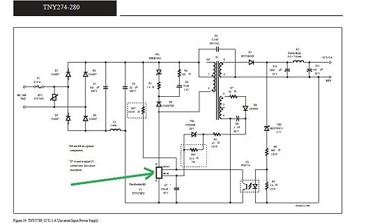
off once the capacitor should be connected at the FEEDBACK pin to the V of the SR FET reaches 0 V. DS SECONDARY GROUND pin of the InnoSwitch3-EP IC. This capacitor A FET with 18 mW R is appropriate for a 5 V, 2 A output, and a should be placed close to the InnoSwitch3-EP IC. DS(ON) FET with 8 mW R DS
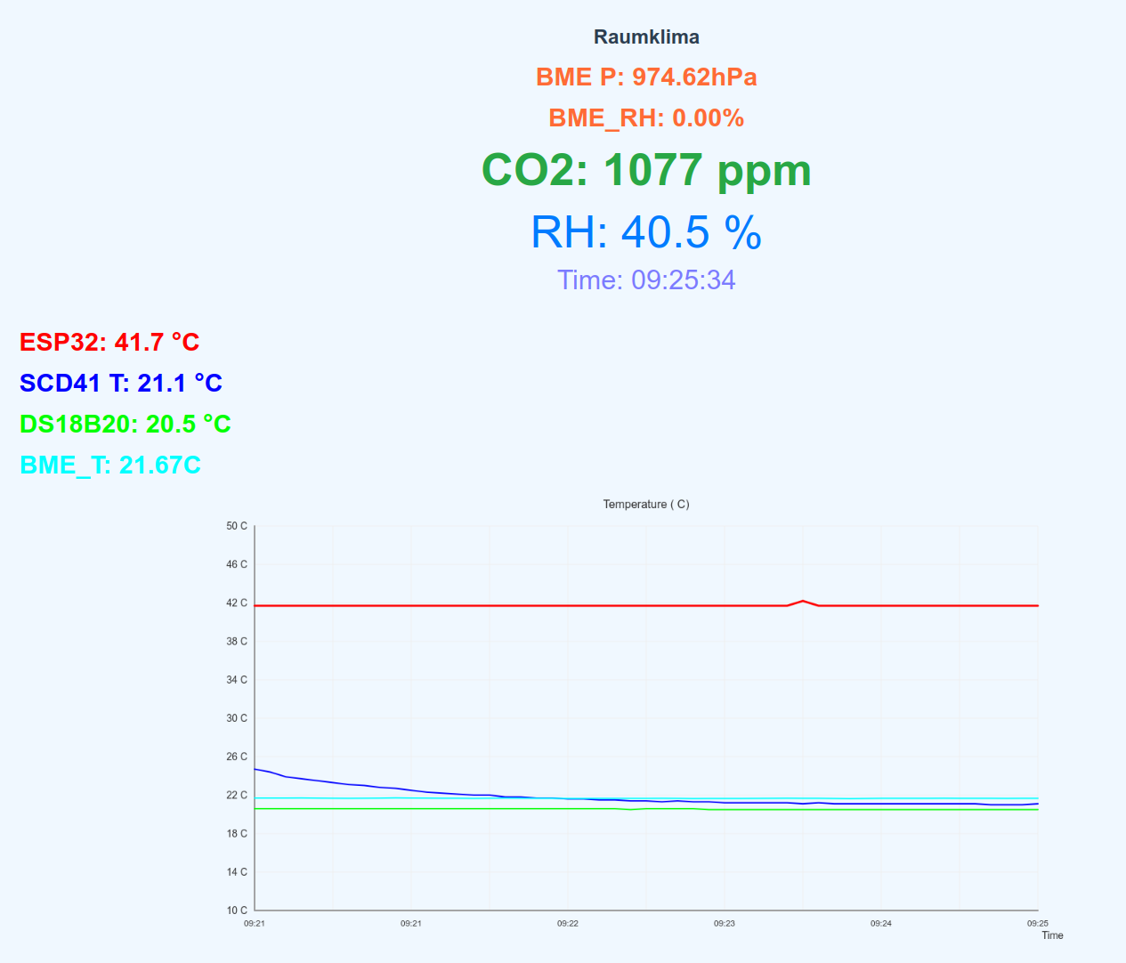
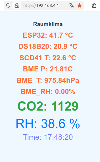
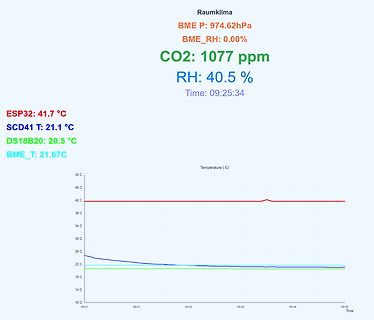
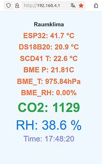
P: 974.62hPa
BME_RH: 0.00%
CO2: 1077 ppm
RH: 40.5 %
Time: 09:25:34
ESP32: 41.7 °C
SCD41 T: 21.1 °C
DS18B20: 20.5 °C
BME_T: 21.67C
Temperature ( C)
50 C
46 C
42 C
38 C
34 C
30 C
26 C
22 C
18 C
14 C
10 C
09:21 09:21 09:22 09:23 09:24 09:25
Time
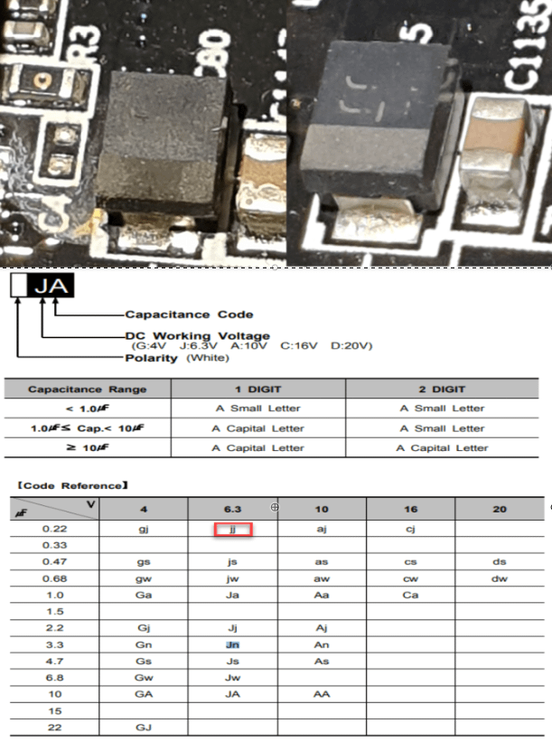
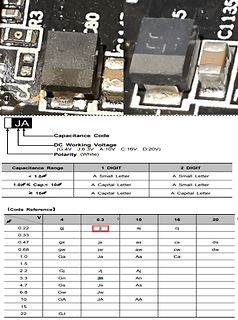
Letter A Small Letter
>= 10µF A Capital Letter A Capital Letter
Code Reference
µF V 4 6.3 10 16 20
0.22 gj jj aj cj
0.33 jj
0.47 gs js as cs ds
0.68 gw jw aw cw dw
1.0 Ga Ja Aa Ca
1.5
2.2 Gj Jj Aj
3.3 Gn Jn An
4.7 Gs Js As
6.8 Gw Jw As
10 GA JA AA
15
22 GJ
gmain.second == 45) // get rtc time at hh:mm:45, but not twice in same minute { if (last_minute_of_ds3231_flag != gmain.minute) { last_minute_of_ds3231_flag = gmain.minute; ds3231_flag = 1; } } else if (gmain.second == 49) { measure_temperature_flag = 1; // start ADC conversion of DS18xx } else if (gmain.second
War für die Lehrlingsarbeiten damals vollkommen ausreichend und dem magerem Lehrlingsbudget mit DM22 angemessen. Gerhard
Kein Problem. Gestern Abend habe ich kurz entschlossen mein Rigol DS1052E auseinander gerissen und den Lüfter ausgebaut. Neuer und leiser Lüfter ist Dank schneller Lieferung schon drin. Und da bin ich bei dem was ich so üblicherweise messe. Das war die Spannung am
wie sinnvoll diese Library ist.... Uuuuuund: ist es legitim, wenn ich "Treiber" für bspw. DHT11 / 22 oder DS18B20 , BM280 mache, dass die Beispiele für diese "Treiber" dieses extendedSerial verwenden dürfen oder ist es hier besser doch nur HardwareSerial von Arduino zu verwenden. Und: für ein vollwertiges
umsonst dazu * BM SKMJ-PN MKP-Kondensator für Pulsbelastung (Snubber) 0,1 µF, 1000 Vdc, bedrahtet RM 22,5 mm ca 60 Stück lose in Tüte EUR 5,- dazu kommt das Porto. Maxibrief bis 1 kg und 5 cm Dicke EUR 2,90. Darüber dann Hermes oder DHL Paket. *** Leider habe ich in letzter Zeit sowohl als Absender
voltage range. Built-in low R high/low side Power-MOSFETS not only reduce external components and has DS(ON) up to 95% efficiency, ideal for 2A output current applicatiThe EA8252 is designed to take into account the light load mode operation. At output loading 10mA condition, the efficiency up to 81%. The
wesentich günstigere Einmalkosten bieten konnten. Technisch hat sich bezüglich der Leiterplatte (ds, dk) selbst aber nur sehr wenig geändert. > Ich verwende heute noch für verschiedene Programmierungen in > Motorsteuerungen DOS-Programme die ich vor 30 Jahren in C selbst > geschrieben habe
2F2VtI8QGtbsm811uiQcUFYm03AQD4Sn4WbkqG7VQWd340050NFp23HhPDrf0qamL5CFZt7tYBK6Jqzs2bMO9WW%2FcEDeQdRjRokrK1zdI0sfX%2Frsh8WK6jBAMaiUgP0Aa1WBom%2FWj0LzIU9g%2BjIpLh5LqUlmTTyHacLly860lbrBSDm22LD3pUIq6l9ppxup1p0%3D%7Ctkp%3ABk9SR76gztfeZw Ist doch ne semiprofessionelle Maschine. Sollte man da nicht einigermaßen akzeptable Ergebnise erwarten können ? Dürfte neu (mit der Absaugung) sicher
ATtiny85, sehr wenige Bauteile, leicht nachzubauen Amadeus-USB - Highspeed-Programmer für PIC18, PIC24, dsPIC30, PIC32, dsPIC33 und AVR. Bietet auch Möglichkeiten zur Fehlersuche. Signalgenerator - Signalgenerator software Time Partition Testing (TPT) - Test-, und Testauswertewerkzeug für eingebettete Systeme
PIC-Chips und wird ständig erweitert. Derzeit können PIC10F, PIC12F, PIC16F, PIC18F, PIC24H sowie dsPIC30F und dsPIC33F programmiert werden. InCircuit-Programmer und -Debugger (www.stolz.de.be) Einfacher Nachbau des Microchip ICD2s. Zum Programmieren und Debuggen. WinPicProg Programmer und Tutorials
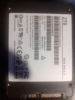
2144JY445213
5VDC 1.0A
WWN:5001B444A7386C7C
R/N: GR960GA-2
Made in China
UK, PO Box 471, Leatherhead, KT22 2LU, UK
MSIP-REM-WDT-GR960GA
CAN ICES-3 @ NMB-3B
DS6024
RoHS
E310334
SATA SSD 2.5"
der Verarbeitung sind (vgl EuGH C-487/21, Österreichische Datenschutzbehörde und CRIF, Rn 32; C-307/22, FT gegen DW, Rn 72). Eine rein allgemeine Beschreibung der Daten, die Gegenstand einer Verarbeitung sind, oder ein Verweis auf Kategorien personenbezogener Daten entspräche dem Erfordernis einer Kopie
-487/21, Österreichische Datenschutzbehörde und CRIF, Rn 41, 45; C-579/21, Pankki, Rn 64 ff; C-307/22, FT gegen DW, Rn 74 f; vgl Bäcker in Kühling/Buchner, Datenschutz- Grundverordnung/BDSG4 [2024] Art 15 DS-GVO Rn 40c ff). [/c] ### Lesestoff: it’s the year of the Zephyr Im Hause NXP verstärkt
2450 MHz Connector Type: SMA (Male/Female) Notch Bandwidth: 2400-2500 MHz Dimensions: 124.0 x 36.0 x 22.0 mm Rejection: ≥50 dB (Not including screws and connectors) Pass Band: 1000-2300 MHz and 2600-6000 MHz Insertion Loss: ≤3.0 dB Environmental Return Loss: ≥12 dB Operating Temperature: -40 to +85 C Power
der Netzschalter S1 und die Sicherung Si1. gangsstrom auf Rechtsanschlag stellen 4. Mit dem Trimmer W22 die Ausgangsspan- Die Stromzuführung erfolgt über die fest mit dem nung auf dem angeschlossen Messgerät auf Gerät verbundene Schuko-Anschlussleitung. 30 V einstellen Zum Öffnen des Gerätes müssen die
network is to assure that, during auto-zero, the output of the comparator is at or near the CINT 0.22 0.22 0.22 µF threshold of the 71C03 logic (+2.5V) while the auto-zero CAZ 1.0 1.0 1.0 µF capacitor is being charged to VREF (+100mV for a 200mV instrument). Otherwise, even with 0V in, some reference
current I (5) 0.8 A OS(5) Maximum sink current IOSI 1 A Gate drive pull-up resistance R V = 1V 8 Ω UP DS HS gate drive pull-down resistance RHS-DN V DS= 1V 1.2 4.3 Ω LS gate drive pull-down RLS-DN V DS= 1V 1 5 Ω resistance LS passive pull-down R LS-PDN 590 kΩ resistance LS automatic turn-on time LS At ENx
Zero gate voltage drain current Vds=17VGS=0V - - 300 uA GSS Gate to source leak current Vgs=10V, V DS=0V - - 5 uA VTH Gate threshold voltage Vds=12V, IDS=1mA 1.6 2.0 2.4 V Pout Output power f=175MHz ,Vds=12.5V 70 75 - W D Drain efficiency Pin=4W, Idq=2.0A 55 60 - % Pout Output power f=520MHz ,Vds=12.5V
Setting registers Code Hex. Function D1 D2 00100001 21H SET CURSOR POINTER X ADRS Y ADRS 00100010 22H SET OFFSET REGISTER DATA 00H 00100100 24H SET ADDRESS POINTER LOW ADRS HIGH ADRS (1) Set Cursor Pointer The position of the cursor is specified by X ADRS and Y ADRS. The cursor position can only be
without data ID code or 7 2 2 = with data ID code data will be output with either16 (code 7 21) or 22 characters (code 7 2 2). For a data output of 22 characters, a 6-character ID precedes the16 characters reserved for the weight or other value. Data Output Format with16 Characters Display segments that
screws ( ). (Fig. 7) DIGITAL P.C.B. b. Remove screw ( ) and screw ( ). (Fig. 6) c. Disconnect CB21, CB22, CB23, CB64 and CB65. (Fig. 6) d. Remove the DIGITAL P.C.B. which is connected directly to the FUNCTION (6) P.C.B. with board-to-board connectors. (Fig. 6) CB64 CB65 CB22 CB23 CB21 4. DIGITAL P.C.B.

 Bild
Bild
 Bild
Bild
 Bild
Bild
 Bild
Bild
 Bild
Bild
 Bild
Bild
 Bild
Bild
 Bild
Bild
 Bild
Bild
 Bild
Bild
 Bild
Bild
 Bild
Bild
 Bild
Bild
 Bild
Bild

 Bild
Bild
 Bild
Bild
 Bild
Bild