-
 Bild
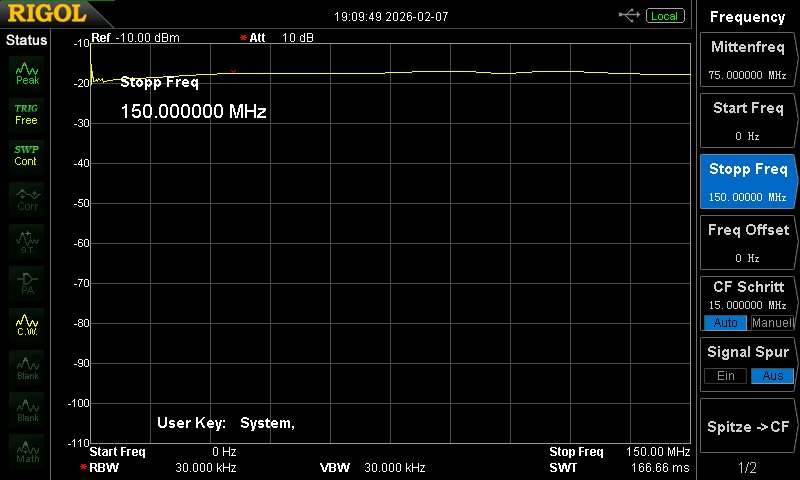
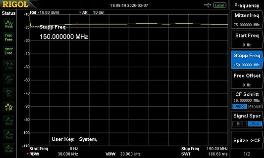
Spektrumanalysator-Display mit Frequenzmessung
-10 Ref -10.00 dBm Att 10 dB Peak -20 Stopp Freq 150.000000 MHz TRIG Free SWP Cont Corr S.T. PA C.W. Blank Blank Math User Key: System, Start Freq 0 Hz RBW 30.000 kHz VBW 30.000 kHz Mittenfreq 75.000000 MHz Start Freq 0 Hz Stopp Freq 150.000000 MHz Freq Offset 0 Hz CF Schritt 15.000000 MHz Auto Manuell Signal Spur Ein Aus Spitze -> CF 1/2 Stop Freq 150.00 MHz SWT 166.66 ms
-
 Bild
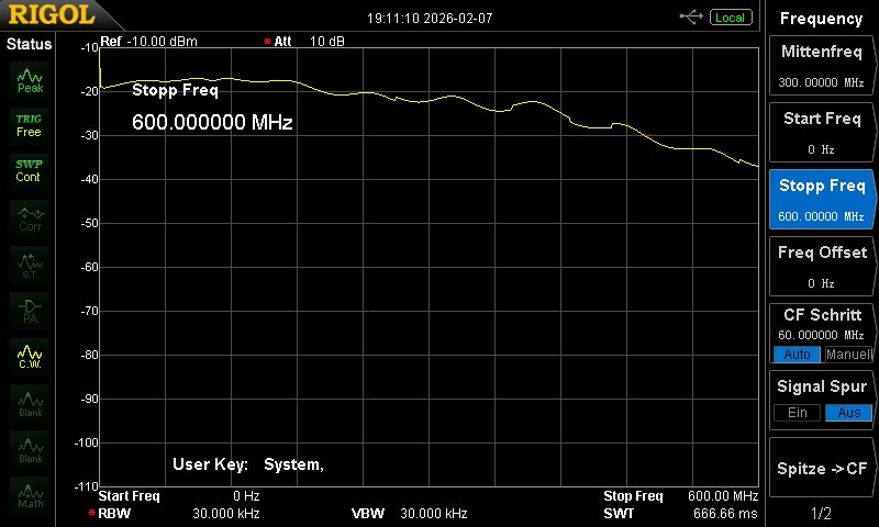
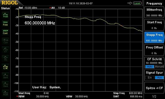
Spektrum eines Spektrumanalysators
2026-02-07 Ref -10.00 dBm Att 10 dB Peak Stopp Freq 600.000000 MHz TRIG Free SWP Cont Corr S.T. PA C.W. Blank Blank Math Mittenfreq 300.000000 MHz Start Freq 0 Hz Stopp Freq 600.00000 MHz Freq Offset 0 Hz CF Schritt 60.000000 MHz Auto Manuell Signal Spur Ein Aus Spitze -> CF User Key: System, Start Freq 0 Hz RBW 30.000 kHz VBW 30.000 kHz Stop Freq 600.00 MHz SWT 666.66 ms 1/2
-
 Bild
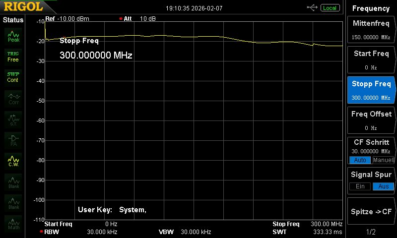
Display eines Spektrumanalysators
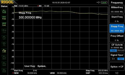
dB Peak -20 Stopp Freq TRIG -30 300.000000 MHz Free -40 SWP -50 Cont -60 Corr -70 S.T. -80 PA -90 C.W. -100 Blank -110 Blank User Key: System, Start Freq 0 Hz * RBW 30.000 kHz Stop Freq 300.00 MHz VBW 30.000 kHz SWT 333.33 ms Mittenfreq 150.00000 MHz Start Freq 0 Hz Stopp Freq 300.00000 MHz Freq Offset 0 Hz CF Schritt 30.000000 MHz Auto Manuell Signal Spur Ein Aus Spitze -> CF 1/2
-
 Bild
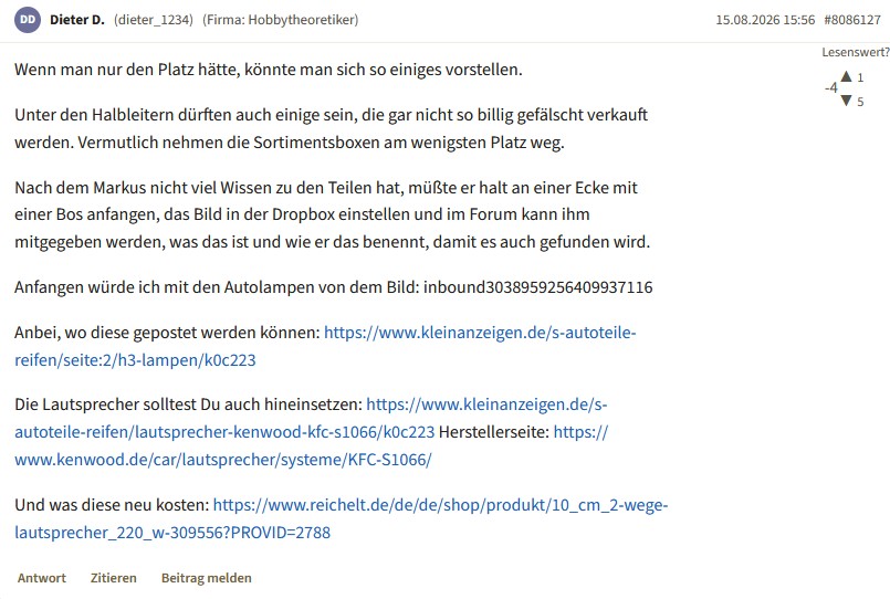
Screenshot eines Forenbeitrags mit Text und Links
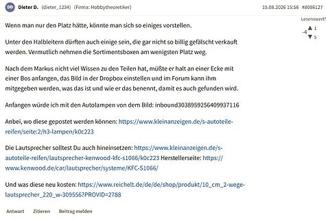
Anbei, wo diese gepostet werden können: https://www.kleinanzeigen.de/s-autoteile-reifen/h3-lampen/k0c223 Die Lautsprecher solltest Du auch hineinsetzen: https://www.kleinanzeigen.de/s-autoteile-reifen/lautsprecher-kenwood-kfc-s1066/k0c223 Herstellerseite: https://www.kenwood.de/car/lautsprecher/systeme/KFC-S1066/ Und das wieso neu kosten: https://www.reichelt.de/de/de/shop/produkt/10_cm_2-wege-lautsprecher_220_w-309556?PROVID=2788 Antwort Zitieren Beitrag melden
-
 Bild
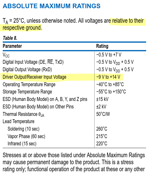
Tabelle mit absoluten Maximalbewertungen eines Datenblatts
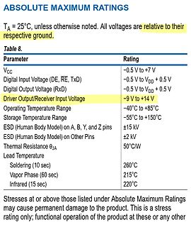
+85°C Storage Temperature Range -55°C to +150°C ESD (Human Body Model) on A, B, Y, and Z pins ±15 kV ESD (Human Body Model) on Other Pins ±2 kV Thermal Resistance θJA 50°C/W Lead Temperature Soldering (10 sec) 260°C Vapor Phase (60 sec) 215°C Infrared (15 sec) 220°C
-
 Bild
Messkurve eines Netzwerkanalysators (S11 Logmag/SWR)
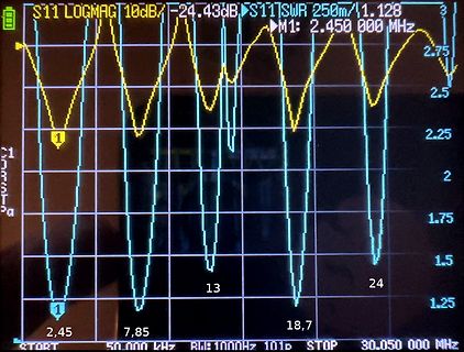
S11 LOGMAG 10dB -24.43dB S11 SWR 250m 1.128 3 M1: 2.450 000 MHz 2.75 2.5 2.25 2 1.75 1.5 1.25 1 2,45 7,85 18,7 START 50.000 kHz R/W 1000Hz 101p STOP 30.050 000 MHz
-
 Bild
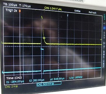
Oszilloskop-Messung zweier Signale
TB: 100µs T: 170µs CH1: 1.24 V\AL 5Msa Refresh Trig?: 2s 1 2 CH2 AC DC GND +T 50 Ω B W L INV Time: (CH2) t1: -264.00µs t2: 282.00µs Δt: 546.00µs 1/Δt: 1.83kHz CH2: 500mV
-
 Bild
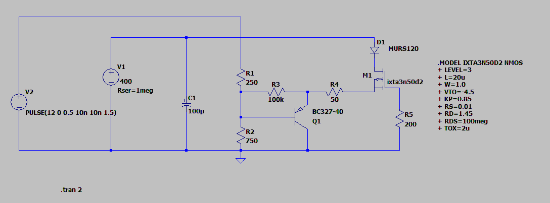
Schaltplan einer Transistorschaltung mit SPICE-Modelltext
V1 400 Rser=1meg C1 100µ D1 MURS120 M1 ixta3n50d2 R1 250 R3 100k R4 50 Q1 BC327-40 R5 200 R2 750 V2 PULSE(12 0 0.5 10n 10n 1.5) .MODEL IXTA3N50D2 NMOS + LEVEL=3 + L=20u + W=1.0 + VTO=-4.5 + KP=0.85 + RS=0.01 + RD=1.45 + RDS=100meg + TOX=2u .tran 2

-
 Bild
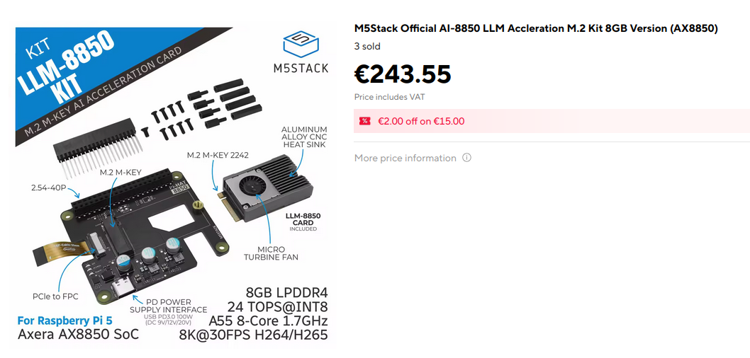
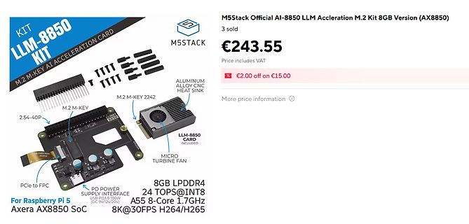
M5Stack AI-Beschleuniger Kit mit AX8850 SoC
KIT LLM-8850 M.2 M-KEY AI ACCELERATION CARD M5STACK ALUMINUM ALLOY CNC HEAT SINK M.2 M-KEY M.2 M-KEY 2242 2.54-40P LLM-8850 CARD INCLUDED MICRO TURBINE FAN PCIe to FPC PD POWER SUPPLY INTERFACE USB PD 3.0W (DC 9V/12V/20V) 8GB LPDDR4 24 TOPS@INT8 A55 8-Core 1.7GHz 8K@30FPS H264/H265 For Raspberry Pi 5 Axera AX8850 SoC M5Stack Official AI-8850 LLM Accrelation M.2 Kit 8GB Version (AX8850) 3 sold €243.55 Price includes VAT €2.00 off on €15.00 More price information
-
 Bild
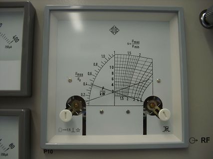
Analoges Messgerät mit Skala für Leistung in kW
TELE FUNKEN s = Umax / Umin 1,0 1,5 2 0,8 10 0,6 8 Umax / U0 4 0,4 6 P kW 2 0,2 1,5 2 3 4 5 -1,5 RF P10
-
 Bild
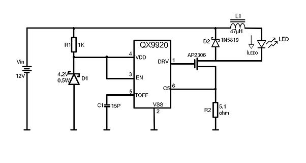
Schaltplan einer LED-Treiberbeschaltung
Vin 12V R1 1K D1 4.2V 0.5W QX9920 VDD 4 EN 3 TOFF 5 VSS 2 DRV 1 AP2306 L1 47uH D2 1N5819 ILEDO LED C1 15P R2 5.1 ohm
-
 Bild
Schaltplan eines Spannungsreglers
U4 +12-24V GND 2 1 F1 D1 1N5819W D2 SMF28A C6 47uF C5 10uF U2 K7805-500R3_C90662 1 Vin 2 GND 3 +Vo C4 22uF +5V GND
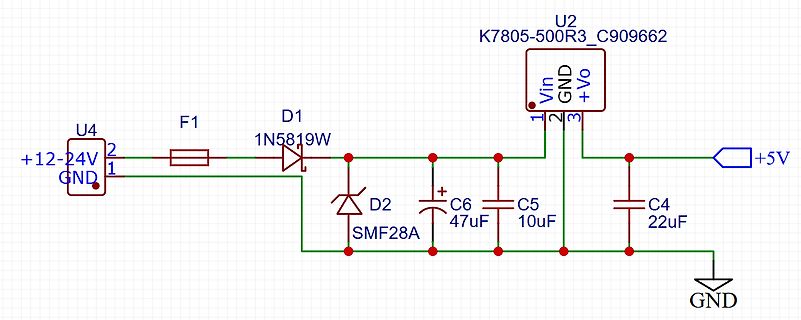
-
 Bild
Schaltplan eines Spannungsreglers
U4 +12-24V GND 2 1 F1 D2 1N418W D1 PTVSHC1SF28VBH C6 47uF C5 10uF U2 K7805-500R3_C90662 1 Vin 2 GND 3 +Vo C4 22uF +5V GND
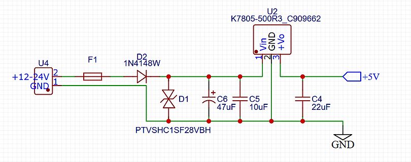
-
 Bild
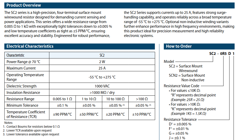
Datenblatt der SC2 Series Drahtwiderstände
Product Overview SC2 Series Electrical Characteristics Power Range @ 70 °C: 2 W Maximum Current: 25 A Operating Temperature Range: -55 °C to +275 °C Dielectric Strength: 1000 VAC / dry Insulation Resistance Resistance Range
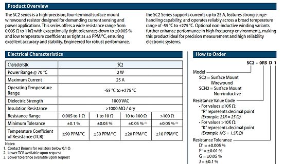
-
 Bild
PCB-Layout einer Treppenlicht-Steuerung
Netz X4 R6 D2 R4 C3 R3 Zeitbasis 10s | 30s JP1 U1 C2 Treppenlicht Einstellungen 0=TEST (3s) 1=Zeitbasis*1 5=Zeitbasis*5 9=Zeitbasis*9 Q1 SW1 K1 R1 R2 D3 R5 Relais EIN F1 Netz 230V/AC L N X1 X2 Taster 230V/AC L - L X3 Relaiskontakt NO potentialfrei 230V/AC max.500W
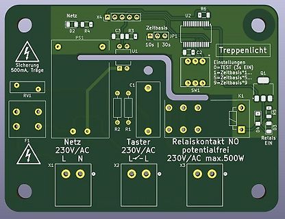
-
 Bild
Technische Zeichnung eines Kühlkörpers mit Diagramm
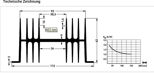
Technische Zeichnung 92 38,5 10 1,6 sk02.eps 4 63 36 2 115 Rth [K/W] 2,5 2,0 1,5 1,0 0,5 50 100 150 200 [mm]
-
 Bild
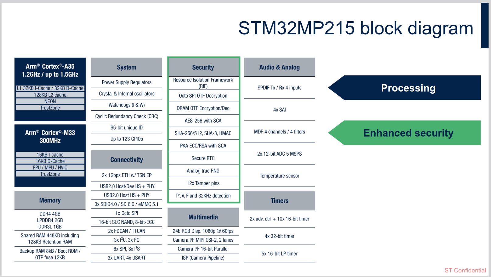
Blockdiagramm des STM32MP215 Mikrocontrollers
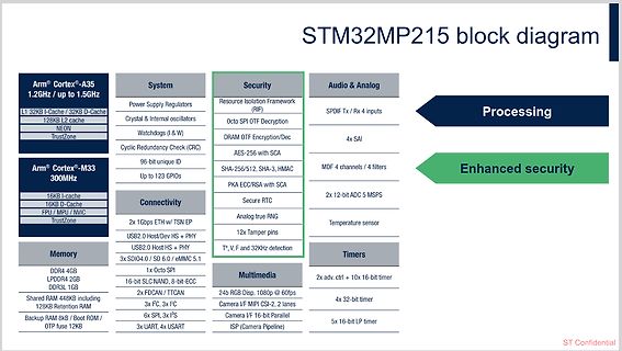
/ Boot ROM/ OTP fuse System Power Supply Regulators Crystal & Internal oscillators Watchdogs (I & W) Cyclic Redundancy Check (CRC) 96-bit unique ID Up to 123 GPIOs Connectivity 2x 10Gbps ETH + TSN USB2.0 Host/Dev HS + PHY USB2.0 Host HS + PHY 3x SDIO/4.0 / eMMC 5.1 1x Octo SPI 2x FDCA N / TTCAN 3x
-
 Bild
Oszilloskop-Display mit Signalverlauf
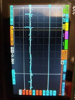
RUN AC 5.20V 10V AUTO SIM 10Hz DUT 50X Z1 T1 4K X T2 11 U1 U2 THR EXT 1T +856 mV 2T +13.3uS W:T +3.86V 1T +640 mV
-
Artikel
Diode
Als Spannungsreferenz sind Band-Gap-Referenzen einer Z-Diode wegen ihrer Temperatur-Drift von 20mV/K vorzuziehen. Z-Dioden werden neben der Anwendung zur Spannungsstabilisierung auch gerne als Spannungsbegrenzer in einem Pegelwandler eingesetzt. Beispiel: RS232-Pegel => TTL-Pegel (+-15V => 5.6V/-0.6V
Beitrag, es muss TLV431 heißen) Forumsbeitrag: Aktive Nachbildung einer HV-Z-Diode, Linearregler für 2kV/2µA Forumsbeitrag: Nachbildung einer Leistungs Z-Diode mittels Transistor Forumsbeitrag: TL431-LiPo-Balancer "reloaded", Balancer mit wenig Ruhestrom (74uA) Forumsbeitrag: Erklärung zu TVS-Dioden Forumsbeitrag
-
 Bild
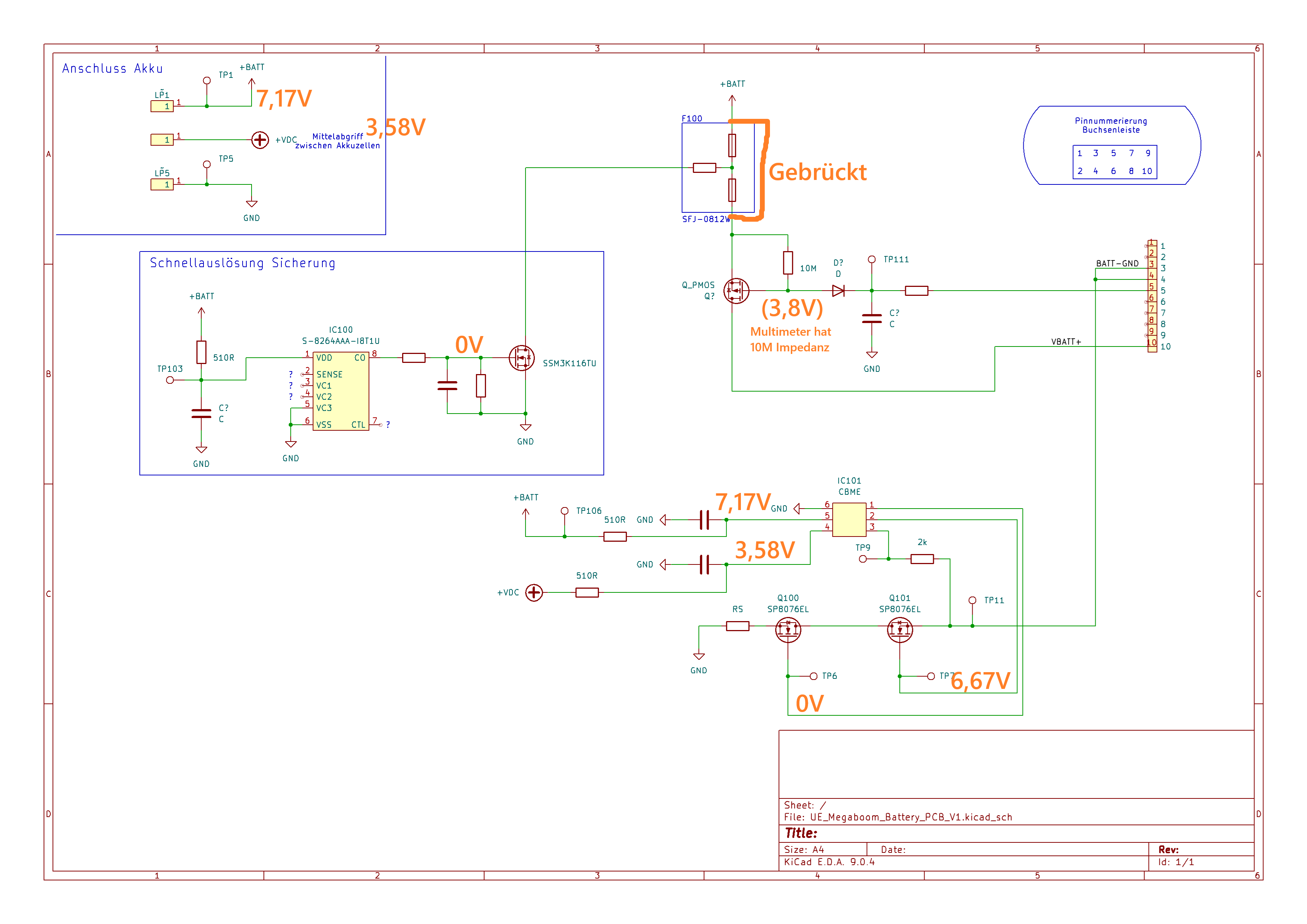
Schaltplan einer Akku-Anschluss-Schaltung
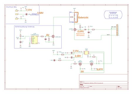
Anschluss Akku TP1 7,17V 3,58V TPS +VDC Zwischen Akku, L1, L2, GND, Pinnummerierung Buchse 1 3 5 7 8 2 4 6 8 10, F100 +BATT, Gebrückt, SFJ-0812W, 10M, Q1, TP111, (3,8V), BAT-GND, C7, C7, VBATT+, GND, Schnellauslösung Sicherung, TP103, 510R, IC100 S-8264AAI-181TU, VDD, CO, VC1, VC2, VC3, VSS, CTL, GND, 0V, 510R, +BATT, TP108, GND, 7,17V, 3,58V, IC101 C8ME, TP9, 2k, Q101 SP8076EL, GND, RS, Q100 SP8076EL, TP6, 6,67V, 0V, Sheet: / File: UE_Megaboom_Battery_PCB_V1.0.sch, Title:, Size
-
 Bild
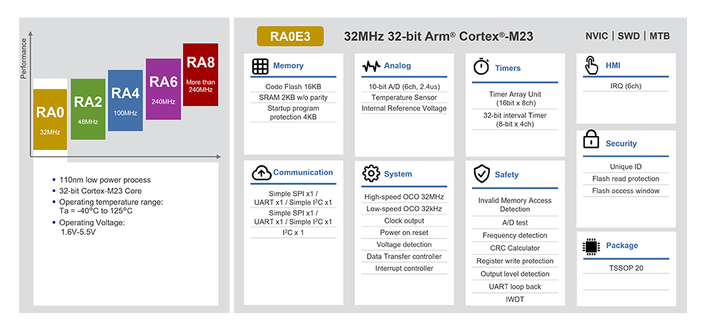
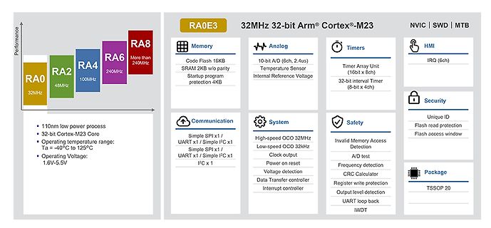
Übersicht der RA-Mikrocontroller-Serie und deren Spezifikationen
RA0 32MHz RA2 48MHz RA4 100MHz RA6 240MHz RA8 More than 240MHz 32MHz 32-bit Arm Cortex-M23 NVIC SWD MTB Memory Code Flash 16KB SRAM 2KB w/o parity Startup program 4KB Analog 10-bit A/D (6ch, 2.4us) Temperature Sensor
-
 Bild
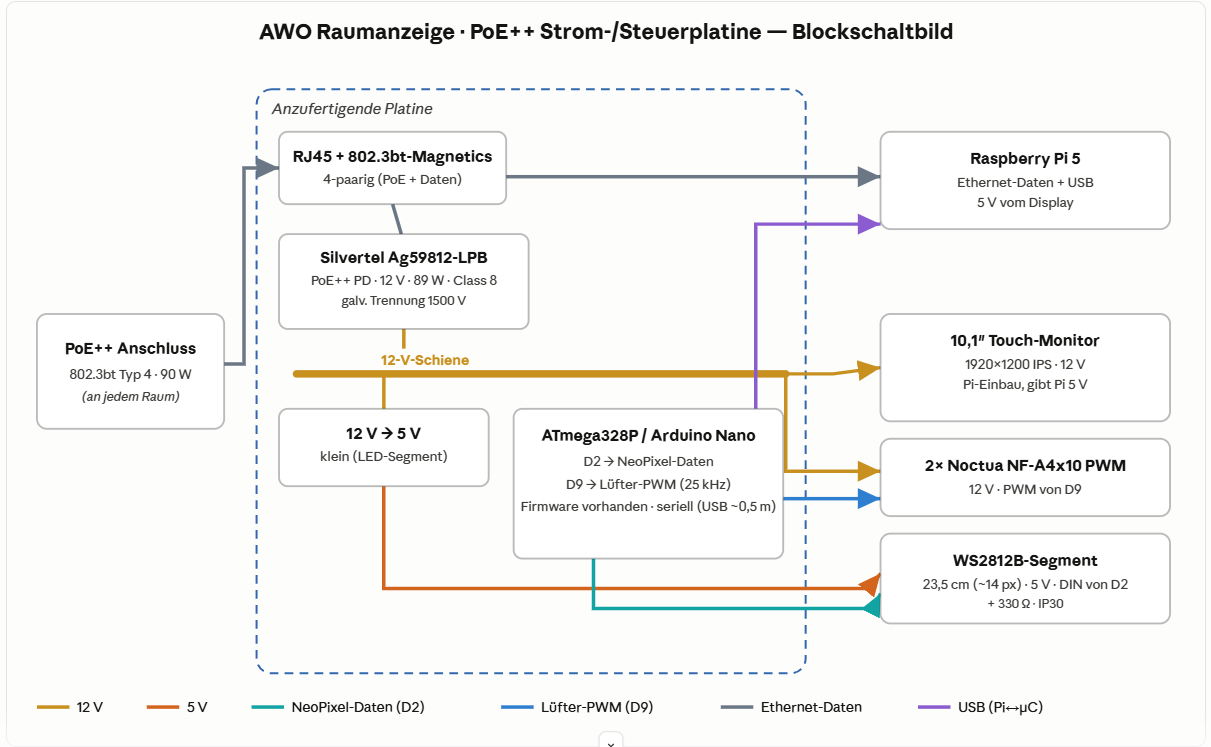
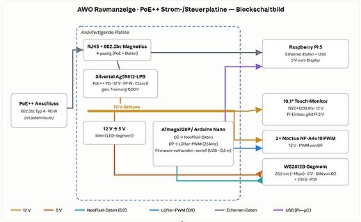
Blockschaltbild einer Strom- und Steuerplatine
/ Arduino Nano D2 -> NeoPixel-Daten D9 -> Lüfter-PWM (25 kHz) Firmware vorhanden · seriell (USB ~0,5 m) 2x Noctua NF-A4x10 PWM 12 V · PWM von D9 WS2812B-Segment 23,5 cm (~14 px) · 5 V · DIN von D2 + 330 Ω · IP30 12 V 5 V NeoPixel-Daten (D2) Lüfter-PWM (D9) Ethernet-Daten USB (Pi->µC)
-
Artikel
Avr-gcc Bugs
end of section are not processed with .align. 2.26 20221 Wrong code with .align and linker relaxation. 2.26 15043 Support -mrmw option for LAC, LAT, LAS and XCH. 2.25 14058 Internal overflow error on > 128kB flash 2.23 13899 Wrong relaxation of R_AVR
from --print-multi-lib and --print-multi-directory 2.2 P-9416 [patch,AVR_TINY] Avoid constraint "w" in delay_basic.h Patch P-9400 [patch] Add avrxmega3 multilibs P-9187 [patch,AVR_TINY] Support 16-bit xtoa functons and more string functions. P-8729 [patch
-
 Bild
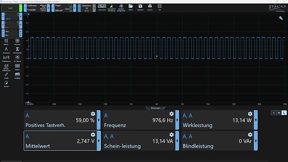
Screenshot einer Oszilloskop-Software mit Messwerten
PicoScope 7 T&M PicoScope 2205A [USB/620] @ 25 MS/s 200 mV/div 5 ms/div 1 kHz Auto A + 10 V A + 8,0 A + 6,0 A + 4,0 A + 2,0 A 0,0 A - 2,0 A - 4,0 A - 6,0 A - 8,0 A -25,0 ms -20,0 -15,0 -10,0 -5,0 0,0 5,0 10,0 15,0 20,0 25,0 Messungen Positives Tastverh. 59,00 % Frequenz 976,6 Hz Wirkleistung 13,14 W Mittelwert 2,747 V Schein-leistung 13,14 VA Blindleistung 0 VAr
-
 Bild
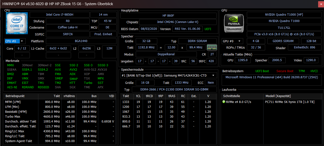
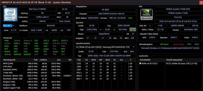
Screenshot einer Hardware-Informationsanzeige eines Laptops
HWINFO64 v8.50-6020 @ HP JP ZBook 15 G6 - System-Überblick CPU Intel Core i7-9850H TDP 45W Codename Coffee Lake-H MCU DE SSPEC SRFCN Platform BGA1440 L1-Cache 63x2 + 63x2 L2 6x256 L3 12M GPU NVIDIA Quadro T1000 [HP GPU #0 4 GB NVIDIA Quadro T1000 PCIe v3.0 x16 (8.0 GT/s) x16 (8.0 GT/s) Speicher
-
 Bild
Schaltplan eines Spannungsreglers mit LM723
W43 2.2k OV3 LM723 CL CS I 47 100pf
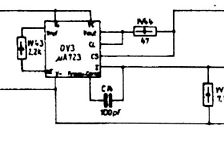
-
 Bild
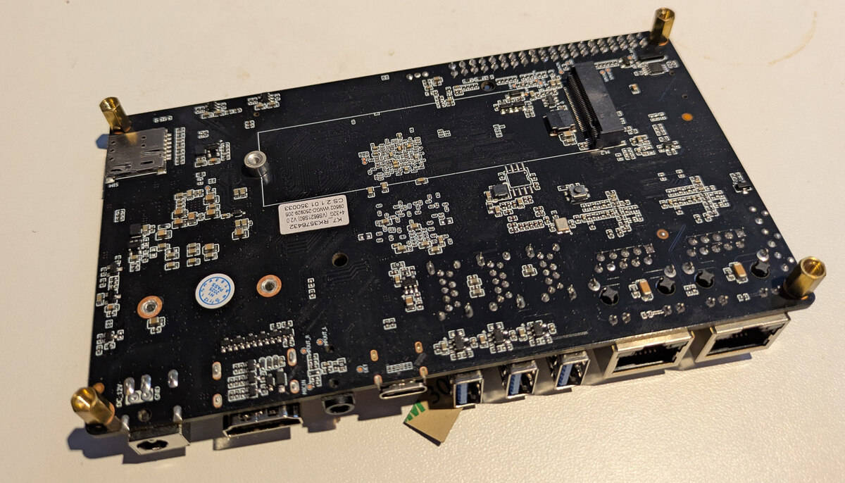
Draufsicht einer schwarzen Leiterplatte mit verschiedenen Anschlüssen
K7_R735R34A2 CS3.01.01.350033 N1602W020020180 V2.0 12V
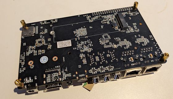
-
 Bild
Sammlung verschiedener Relais und Bauteile
TAKAMIYA HALDIW 2W-K, OMRON TYPE LY1, SDS, SIEMENS, AXICOM, 12VDC, 2A, GBR 12-3 13.012, GBR 12-3 9.005
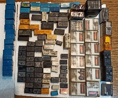
-
 Bild
Taalas HC1 Technology Demonstrator Leiterplatte
Products Taalas HC1 Technology Demonstrator Runs Llama 3.1 8B model TSMC 6nm | 815mm2 | 53B Transistor 2.5 kW Server TAALAS
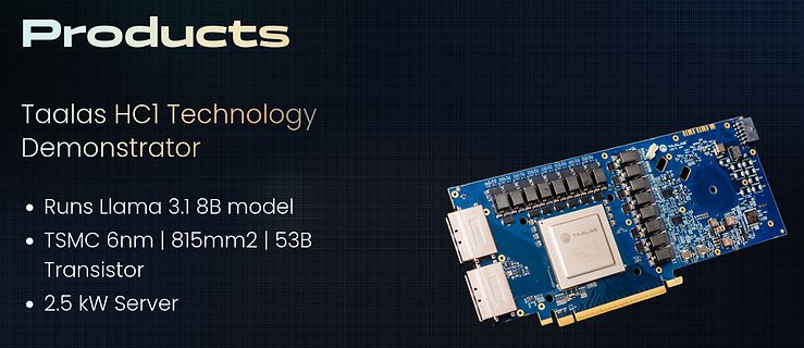
-
 Bild
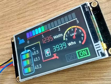
Display einer Energieüberwachungseinheit auf Holzuntergrund
3221-SZ 0 1 2 3 1235 Watts kW h 0 1 2 3 4 5 6 7 8 3939 Whs °C 48.5 43.1 43.3 OFF ON
-
 Bild
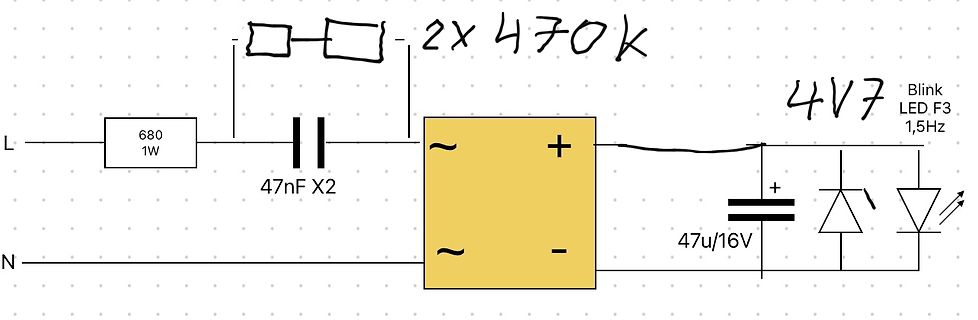
Handgezeichneter Schaltplan eines Netzteils
L 680 1W N 2x 470K 47nF X2 ~ + ~ - 4V7 47u/16V Blink LED F3 1,5Hz
-
 Bild
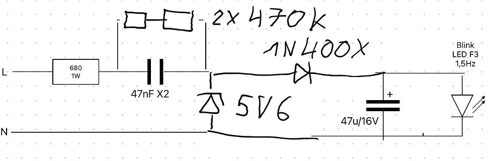
Handgezeichneter Schaltplan eines Blinklicht-Netzteils
L 680 1W 2x 470K 47nF X2 1N400X 5V6 47u/16V Blink LED F3 1,5Hz N
-
 Bild
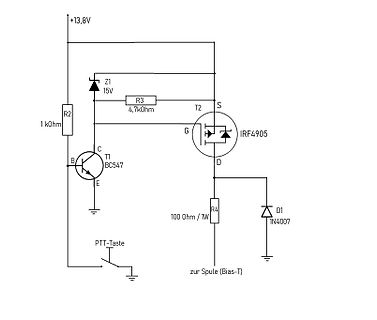
Schaltplan einer MOSFET-Treiberstufe
+13,8V Z1 15V R3 4,7kohm T2 S IRF4905 R2 1 kOhm C B T1 BC547 E D R4 100 Ohm / 1W D1 1N4007 PTT-Taste zur Spule (Bias-T)
-
 Bild
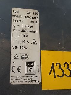
Typenschild eines Elektromotors
Typ GE 120 Masch-Nr.: 40021259 230 V~ 50 Hz PI = 2,2 kW n = 2800 min-1 In = 10 A X 16 A S6=40% GS CE 20 kg 60059670104 Viking-Umwelttechnik GmbH Munchner Straße 17-21 A-6330 KUFSTEIN AUSTRIA
-
 Bild
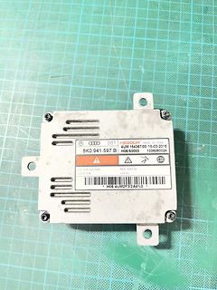
Audi-Elektronikbauteil auf grünem Untergrund
Audi DOT KEBODA MADE IN CHINA 4UM 154367/00 18-03-2015 8K0.941.597.B H06/50003 1036060024 035/03R/045/04R MAX 1300V DC 42V AC 2000H/35W H06 4UM2F3I2A4%0
-
 Bild
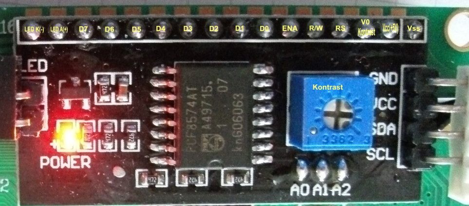
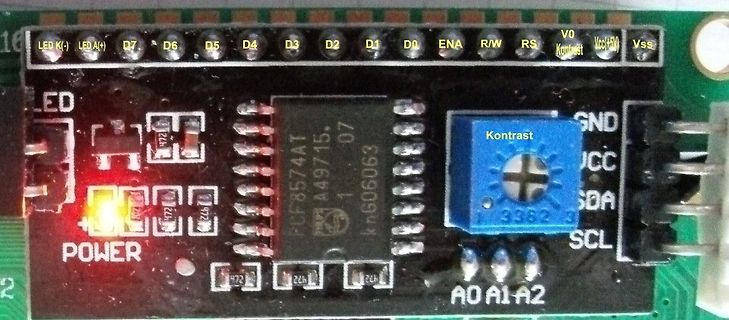
I2C LCD Adapter Modul mit PCF8574AT Chip
LED K(-) LED A(+) D7 D6 D5 D4 D3 D2 D1 D0 ENA R/W RS VO Kontrast Vcc(+5V) Vss LED POWER PCF8574AT A49715. 07 kn606063 GND VCC SDA SCL A0 A1 A2 Kontrast
-
 Bild
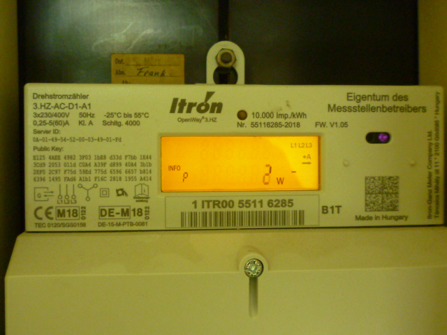
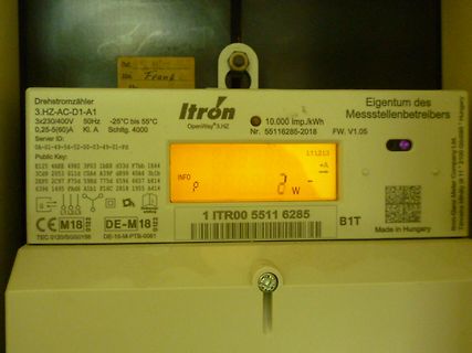
Itron Drehstromzähler mit Display
-01-Pd Public Key: E125 4EES 4982 3F03 1b88 d3d7 F7b8 1844 3089 2053 011d C0A4 A39F d899 40A4 3b1b 2EFO 2C97 F75d 53E9 775d 6596 6657 b814 6396 1495 F4d6 A1b6 F1C6 2818 1955 A414 Itron OpenWay 3.HZ Eigentum des Messstellenbetreibers 10.000 Imp./kWh Nr. 55116285-2018 FW. V1.05 L1 L2 L3 INFO 0 W CE M18
-
 Bild
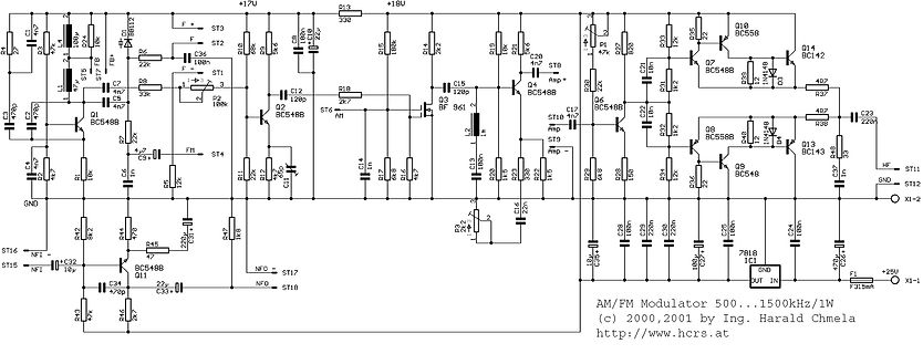
Schaltplan eines AM/FM Modulators
ST3 ST2 ST1 ST4 ST6 ST9 ST17 ST18 ST11 ST12 HF GND X1-2 AM/FM Modulator 500...1500kHz/1W (c) 2000,2001 by Ing. Harald Chmela http://www.hcrs.at BC548B BC548B BC548B BC548
-
 Bild
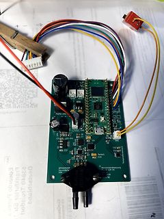
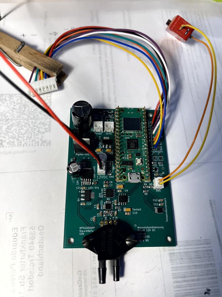
Bestückte Leiterplatte mit Mikrocontroller und Verkabelung
Pumpe Ventil LED1 LED2 Digital-5V1 12VDC GND C21 C22 LDO-5V1 C7 C8 C9 R5 R7 R9 R10 R11 R12 SW1 SW2 Temperatursensor MPX205DP 5m=49kPa 10V PicoW 12V DC