-
Thread
ESP32 mit 3,3V PWM einen 3,7V Motor betreiben
A maximum of 22 μF is recommended. > Aluminum-electrolytic capacitors are not > recommended for low-temperature applications of <= -25°C https://ww1.microchip.com/downloads/en/DeviceDoc/22057B.pdf Der relativ hohe Ruhestrom des MCP1826 passt allerdings nicht gut zum Deep-Sleep Modus, falls dieser
verkleinern. Aufpassen, dass die Motorspannung nicht zu groß wird, sonst leiten die immer, egal ob der ESP HIGH oder LOW liefert. Viel Spaß noch. Paul -. schrieb im Beitrag #8063060: > es funktioniert mit 10k Richtung > ground und 1k vor dem Gate Wenn es P-Kanal FETs sind, ist es evtl. sinnvoller, den
-
Thread
Suche Transistor C3333
Suche nach C3333 https://www.alldatasheet.com/datasheet-pdf/pdf/30185/TOSHIBA/C3333.html npn High Voltage Switching Applications Color TV Chroma Output Applications High voltage: VCEO = 250 V Low Cre: 1.8 pF (max) Complementary to 2SA1320 https://www.reichelt.de/de/de/shop/produkt/bipolartransistor_npn
-
Thread
Arduino App Lab-Erweiterung, Jetson-Abkündigungen, neue Messtechnik und mehr
network-composition-aware dynamic speed selection that improves congestion handling and supports higher device density [/c] Im Hintergrund wurden außerdem Optimierungen vorgenommen, um den Energieverbrauch des Funksystems zu reduzieren. ### Arduino Lab: Möglichkeit zur Erzeugung hauseigener
vermeldet man folgendes: [c] AMD Versal Prime VM2152 – Key Highlights • 6400 Mb/s LPDDR5 → High bandwidth, efficient memory subsystem • 5600 Mb/s DDR5 → Balanced performance for embedded systems • 112G Transceivers → Enables high data rate connectivity • 400G High-Speed Crypto
-
Thread
Mehr Zusammenarbeit zwischen CIX und OrangePi, Raspberry Pi-Sicherheitsupdate uvam
interested in improving the software for the CIX P1. It’s unclear whether any of that will help fix the high idle power consumption, which is a non-starter for some people. I suspect I might require SoC-level power management optimizations that would probably have to be handled by CIX themselves, although
folgendes: [c] With support for both 2.4 and 5 GHz bands, both MCUs deliver superior throughput, low latency, and reduced power consumption. The dual-band capability dynamically selects the most suitable band based on real-time conditions, ensuring a stable and high-speed connection even in environments
-
Thread
Reparatur Yamaha DSP Z7
Labornetzteil. Ich denke der BD9011 ist hin. Normal soll der DET2 Ausgang bei FB2 < 0,56V auf High und damit der Open-Drain Ausgang runterziehen. Ich hab aber da 5V gemessen (DET2). Gleichzeitig ist FB2 aber 0,179V und nicht 0,8V (normal). Sonst fällt mir nix mehr ein. Chip auf Ali bestellt (
da steht PS_PRT (power supply protection) low active - d.h. 5V wäre gut/ok?
-
Thread
Tipps zur Speicheranalyse gesucht
und laufen lässt, ist auch alles schick? Das wäre Werkzeug erster Wahl um Speicherfehler auf einem High Level OS aufzudecken. Mach’s nicht ohne Debugger auf dem Zielsystem. Das ist gut investiertes Geld bzw Zeit, gerade wenn es ein kommerzielles Projekt ist. Für einen verplemperten Entwicklertag kann
0x20080000 */ _estack_core1 = _estack_core0 - 0x2000; /* 8 KB darunter = 0x2007E000 */ _stack_low_core0 = _estack_core0 - 0x2000; /* untere Grenze */ _stack_low_core1 = _estack_core1 - 0x2000; [/pre] und per so etwa in die CMakeLists.txt gebaut: die dritte Zeile gab es vorher nicht.
-
Thread
Funktechnisches, neuer OrangePi, SigVSA und mehr
My and Google Find Hub networks, both crowdsourced location-finding ecosystems that use Bluetooth Low Energy (LE) and nearby smartphones to securely detect and report the location of tagged devices without GPS. . . . The nRF54L15 Tag supports rapid prototyping of Matter-enabled smart home products
measurements and provides high common-mode rejection for improved measurement accuracy. --- via https://www.siglenteu.com/news-article/siglent-launches-8-ghz-active-differential-probe-for-high-speed-and-rf-applications/ [/c]
-
Thread
Copilot für Microcontroller verwenden
devdesc", auch OpenSource). Deckt auch > heute noch die meisten Beduerfnisse ab. Auch ziemlich High-Level, damit kann ich keinen Accelerometer-IC ansteuern.
devdesc", auch OpenSource). Deckt auch >> heute noch die meisten Beduerfnisse ab. > > Auch ziemlich High-Level, damit kann ich keinen Accelerometer-IC > ansteuern. Der devdesc XML-Dialekt ist wie SVD, kann nur eim bisschen mehr. Mehr als die Low-Level-Registermap und die generierten Header braucht
-
Thread
China DC-DC Wandler reengineering
Das unbekannte IC im PDF ist ein High/Low Side Gate Treiber. C14 und D1 sind die Charge Pump für den oberen Transistor, da sollten ca. 10V relativ zum Mittelabgriff zwischen den Ausgangstransistoren anliegen. Die DC Messwerte an allen
-
Thread
Raum Köln: Wer kann mit SDR/Spektrum eine Auffälligkeit sichtbar machen?
sein, aber dazu noch tiefe Frequenzen... Ob Terroristen, fremde Geheimdienste, Außerirdische mit High Tech- Spezialwaffen zu Gange sind... da muß man ja schon ziemlich bedeutend sein.
Moin, danke, das ist konkret hilfreich. Der nächste sinnvolle Low-Budget-Aufbau wäre dann wohl: - Luftschall: ECM8000 + Interface - Körperschall: dynamisches Mikro / Lautsprecher als Sensor / Kopfhörerkapsel-Lösung - beides parallel aufnehmen - Messpunkte: Bett
-
Thread
Warum ist die USB/CDC Implementierung der Cube HAL so groẞ?
ergibt: [c] void setup() { pinMode(PC13, OUTPUT); } void loop() { digitalWrite(PC13, LOW); Serial.println("Tick"); delay(500); digitalWrite(PC13, HIGH); Serial.println("Tack"); delay(500); } [/c] Das andere Projekt (für die STM32 Cube IDE) habe ich angehängt
Reference Manual vom STM32F3 steht dazu nichts. Laut https://deepwiki.com/grblHAL/STM32F3xx/4.2.3-usb-low-level-configuration geht es beim PCD offenbar darum, Takt und I/O Pins für USB zu konfigurieren. Also das, was die kleinere Implementierung mit nur wenigen direkten Registerzugriffen macht. > mit
-
 Bild
Bild
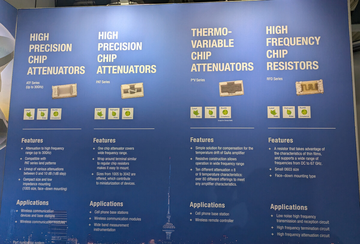
Werbeübersicht für Hochfrequenz-Chip-Dämpfer und -Widerstände
HIGH PRECISION CHIP ATTENUATORS ATF Series (up to 30GHz) Lead free Halogen free RoHS Compliant HIGH PRECISION CHIP ATTENUATORS PAT Series Lead free Halogen free RoHS Compliant THERMO-VARIABLE CHIP ATTENUATORS
-
Thread
LEDs in bestehende Schaltung einbinden
Übrigens ist das Label [GRÜN]> eigentlich falsch benannt, denn die grüne LED leuchtet *nicht*, wenn GRÜN high ist. Es müsste also /GRÜN oder GRÜN# heißen, weil das Signal low-aktiv ist. .● Des|ntegrator ●. schrieb im Beitrag #7968262: > guck ich verkehrt oder wäre die grüne LED lt. Plan verpolt? Mal davon
-
Thread
NFC-Jukebox auf Basis einer bestehenden Bluetooth-Box
der vom Wemos gesteuert wird und den Verstärker + Boost-Wandler freischaltet. - Oder ein einzelner High-Side-Switch, der die komplette Last (5 V + Verstärker) steuert. Was wäre hier die sauberste und energieeffizienteste Lösung? Ich freue mich über Tipps zu: - geeigneten Verstärkern (klein, effizient
das Aufladen einfacher, DFPlayer geht bis ca. 3V runter, der ESP ist auch 3.3V, der PNY m.W. auch. Low-Drop-Regler von 4.2V…3.3V -> 3.3V könnte reichen, und wie weit unter 3.3V das noch funktioniert wäre zu testen, aber viel Kapazität geht "da unten" nicht verloren. Für den Verstärker: Wieviel Leistung
-
Thread
Neues Blackboard mit STM32H723
/1005010466566322.html Das ist ein ST32H7R3, der läuft mit 600MHz und hat vor allen Dingen USB HIGH Speed im Chip. Und einen 16Bit Bus bis 50MHz. Da habe ich ein Board hier aber auch noch nichts damit gemacht. Ist leider nur ein Blink Demo drauf ohne USB.
Noch ist nichts dafür geschrieben, ich bin gespannt. Ich habe mir vorgenommen mit Cube-IDE aber LowLevel auf Registerebene ohne HAL zu arbeiten. Leider hänge ich immer noch an der RCC-Konfig und bekomme meinen Wunschtakt nicht hin. Diese H7 sind schon etwas tricky...
-
Thread
Sporadischer digitaler Glitch beim Abspielen von Videos und Audio auf Laptop Vector GP76
Bei Multimediawiedergabe wirft Windows den "High-Precision Timer" an. Scheinbar ist die gelobte Gaminghardware dafür zu schlapp, oder falsch konfiguriert. Ein hülfreiches Programm zur Diagnose, misst die Zeiten, die ein: "Deferred Procedure
Audio-Codec von dem älteren Format MPEG-1 Layer II auf den modernen Standard AAC-LC (Advanced Audio Codec – Low Complexity)..." Einige Digital-Kabel-Radio-Geräte blieben entweder ganz stumm oder hatten Probleme mit dem Update. Es lief am Anfang nicht ganz rund. MER musste mindestens 31 dB sein und Pegel über
-
 Bild
Bild
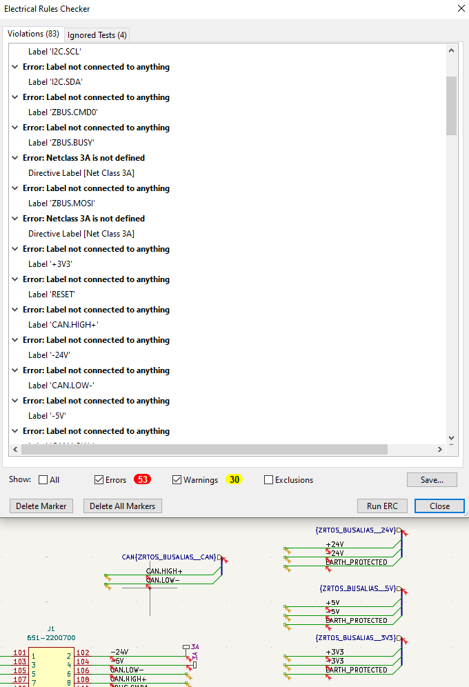
Electrical Rules Checker Fehlermeldungen in EDA-Software
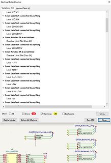
: Label not connected to anything Label 'RESET' Error: Label not connected to anything Label 'CAN.HIGH+' Error: Label not connected to anything Label '-24V' Error: Label not connected to anything Label 'CAN.LOW-' Error: Label not connected to anything Label '-5V' Show: All Errors 53 Warnings 30 Exclusions Save... Run ERC Close J1 651-2200700 CAN[ZRTOS_BUSALIAS__CAN] CAN.HIGH+ CAN.LOW- {ZRTOS_BUSALIAS__24V} +24V EARTH_PROTECTED {ZRTOS_BUSALIAS__5V} +5V EARTH_PROTECTED {ZRTOS_BUSALIAS__3V3} +3V3 3V3 EARTH_PROTECTED 101 102 -4V 103 104 105 106 CAN.LOW- 107 108 CAN.HIGH+
-
Thread
Cyberagentur startet Rezertifikationsprojekt, Raspberry Pi-AI-Assistent, RISC/V und mehr
a set grid over a plane’s surface and provides a full-surface visual analysis by taking up to 600 high definition photos. The coatings management software then analyzes the images to flag any issues or wear of the coatings. Employing an advanced two-drone system further boosts Aerofleet’s ability to
dT (frequency temperature slope)—up to 25X better • 6 × 10⁻¹² Allan Deviation (ADEV)—up to 8X lower • ±50 ppb frequency stability over -40 to 105°C—up to 4X better • 3.2 mm × 2.5 mm (8 mm²) footprint—up to 2X smaller • Digital frequency tuning simplifies timing-aware network design
-
Thread
Funkamateur Bauteiletester BT2 BX232 Wer kann mir helfen?
github-Repo die passende ist, hier nochmal für alle Fälle die rückgelesene Firmware. Die Fuses sind: low: 0xE2, high: 0xD9, efuse: 0xFC Vermutlich wird es mal wieder jemand brauchen, denn die relativ schlecht schützbaren Eingänge des Controllers sind natürlich der wunde Punkt dieser Geräte.
-
Thread
ADS1115 auslesen Assembler
Saleae-Geräte). Und ein LA hat recht sicher andere Schaltschwellen, ab der er Signale definiert als Low oder High erkennt als die I2C-Eingangsstufe des ungenannten µC des Threadstarters.
-
Thread
[V] ältere Bauteile abzugegben
schon abgedeckt sein. MAX1200 "+5V Single-Supply, 1Msps, 16-Bit Self-Calibrating ADC" MAX1011 Low-Power, 90Msps, 6-Bit ADC MAX197 "Multi-Range (±10V, ±5V, +10V, +5V), Single +5V, 12-Bit DAS with 8+4 Bus Interface" MAX195 16-Bit, 85ksps ADC with 10μA Shutdown MAX194 14-Bit, 85ksps ADC
1 Kanal ADG201 analogschalter 4 fach AD558 D/A Wandler 8bit 1 Kanal MAX472 Precision, High-Side Current-Sense Amplifiers
-
Thread
Controller PLL TBB146
Kathode an den Zeileneingängen. Zusammen mit dem S187 ergab das dann 10 schaltbare Frequenzen. Für ein "high" am Teilereingang wurde die Diode "durchgebrannt" (Eingang offen), blieb sie intakt, ergab das "low".
-
Thread
Problem mit dem Funkuhrbausatz von Sol-expert
Logikausgang, der die Hüllkurve der Amplitudenmodulation ausgibt. Die Sekundenpulse sind dann aktiv high oder low. Du kannst Dein Modul austauschen wenn die Betriebsspannung passt, also 1,8, 3,3 oder 5 V, und wenn die Polarität des Ausgangs passt.
-
Thread
Sat schüssel + verteiler , kein bild
zwei Kabeln. Oben sind die vier Eingänge von den "klassischen" LNBs an der Schüssel (hor/vert/ LowBand/HighBand), rechts sind die zwei Ausgänge zu den Unicable-Empfängern, jeder Ausgang kann vier Unterbereiche, also maximal acht Empfänger. Ist der wirklich defekt? Das ganze entwickelt sich allmählich
-
 Bild
Bild
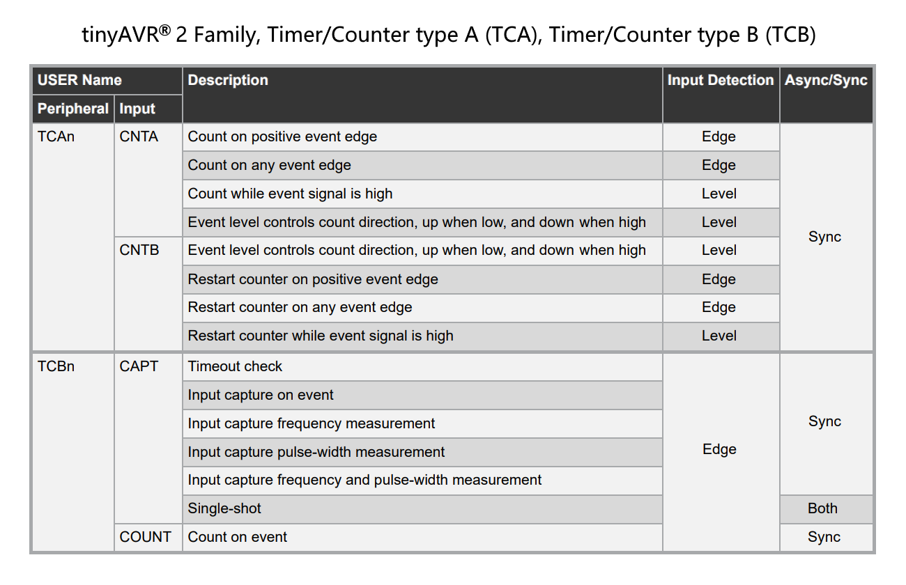
Tabelle der Timer/Counter Funktionen von tinyAVR Peripherie
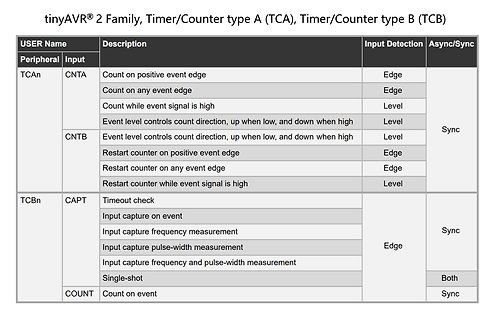
TCAn CNTA Count on positive event edge Edge Count on any event edge Edge Count while event signal is high Level Event level controls count direction, up when low, and down when high Level CNTB Event level controls count direction, up when low, and down when high Level Restart counter on positive event edge Edge Restart counter on any event edge Edge Restart counter while event signal is high Level TCBn CAPT Timeout check Sync Input capture on event Edge Input capture frequency measurement Edge Input capture pulse-width measurement Edge Input capture frequency and pulse-width measurement
-
Thread
Seltsames Verhalten eines Beschleunigungssensors
sonst einem LA) auch noch den Datenverkehr auf > dem I2C-Bus. Für I2C reicht selbst so ein 4€ Low Cost Logicanalyzer mit dem Cypress Chip drauf (24MSPS@8Ch). Oder ein Raspberry Pi Pico Board (ab 1,70€ bei Ali) mit dem Gusmanb Logicanalyzer (200MSPS@24Ch). Oder wenn ihr euch richtig in Unkosten stützen
reset_int = 1 now (clears any latched interrupts) INT_od = 0 → push-pull output INT_lvl = 1 → active-high INT pin 9. 27, 21, 01 0x21 → INT_LATCH 0x01 → latch_INT = 0001 → temporary latch for 250 ms Sieht alles nicht verkehrt aus. Wir jagen gearde einen Verdacht nach und morgen werde ich mehr