-
PDF
DM8603EP.pdf
...............................................................................................105 14. ORDERING INFORMATION.....................................................................................107 Preliminarydatasheet 7 DM8603-12-DS-P01 November8,2010 Downloaded from Elcodis.com electronic
in „[V] DM8203 & DM8603“ · Markt ·
-
PDF
2304140030_QX-Micro-Devices-QX2304L30T_C219035.pdf
12 of 14 QX2304_DS03CN (Shenzhen) Co., Ltd. www.qxmd.com.cn Machine Translated by Google QX2304 High-efficiency PFM synchronous boost DC/DC converter TO92 package dimension diagram: QX2304_DS03CN Quancore Electronics
in „IC (SOT23-3?) aus Christbaumkerze identifizieren“ · Mikrocontroller und Digitale Elektronik ·
-
PDF
LM317_Datenblatt.pdf
available at: www.st.com. ECOPACK is an ST trademark. 8.1 TO-220 (single gauge) package information Figure 14. TO-220 (single gauge) package outline 8174627_5 DS0433 - Rev 22 page 14/34 LM217, LM317 TO-220 (single gauge) package information Table 7. TO-220 (single gauge) mechanical data mm Dim. Min. Typ. Max. A 4.40 4.60 b 0.61 0.88 b1 1.14 1.70 c 0.48 0.70 D 15.25 15.75 E 10.00 10.40 e 2.40 2.70 e1 4.95 5.15 F 0.51 0.60 H1 6.20 6.60 J1 2.40 2.72 L 13.00 14.00 L1 3.50 3.93 L20 16.40 L30 28.90 ∅P 3.75 3.85 Q 2.65 2.95 DS0433 - Rev 22 page
in „12V Membranpumpe (KNF) läuft nur mit halber Leistung bei interner 3V-Steuerspannung (LM317)“ · Analoge Elektronik und Schaltungstechnik ·
-
PDF
Battery-Protection-LiIon-2S-HY2120.pdf
BSC R 0.10 - - R1 0.10 - 0.25 θ 0° 4° 8° θ1 5° - 15° θ2 5° - 15° © 2009-2015 HYCON Technology Corp DS-HY2120-V15_EN www.hycontek.com page19 HY2120 2-Cell Lithium-ion/Lithium Polymer Battery Packs Protection ICs 14.Tape & Reel Information 14.1.Tape & Reel Information---SOT-23-6 (Type 1) Unit : mm. 14.1.1
in „[S] LiIo-Akku“ · Markt ·
-
PDF
DS_DA221.pdf
.......................................................24 2/ 34 www.miramems.com Mar. 2023 Rev 0.1 DS_da221 7.14. INT_SET2 (17H)......................................................................................................................................25 7.15. INT_MAP1 (19H)................
in „Seltsames Verhalten eines Beschleunigungssensors“ · Mikrocontroller und Digitale Elektronik ·
-
PDF
DM8203.pdf
0, RW Vendor power down control test * When selected, the power down value is control by Register 14H 40 Preliminary datasheet DM8203-15-DS-P05 October23,2008 DM8203 2-port switchwithMII/RMIIInterface 8.12 (Specified config) Register – 14H Bit Bit Name Default Description 15 TSTSE1 0,RW Vendor test
in „[V] DM8203 & DM8603“ · Markt ·
-
PDF
t1610.pdf
F 6.20 6.60 0.2441 0.2598 I 3.73 3.88 0.1469 0.1528 L 2.65 2.95 0.1043 0.1161 I2 1.14 1.70 0.0449 0.0669 I3 1.14 1.70 0.0449 0.0669 I4 15.80 16.40 16.80 0.6220 0.6457 0.6614 M 2.6 0.1024 1. Inch dimensions are for reference only DS2114 - Rev 11 page 9/18 T1610, T1635, T1650, BTA16, BTB16
-
PDF
dm9161-ds-f05_091008.pdf
.........37 7.2.12 Power Down Mode......................................20 2 Final Version: DM9161-DS-F05 September 10, 2008 DM9161 10/100MbpsFastEthernetPhysicalLayer TX/FXSingleChipTransceiver 9.4.14 Auto-negotiation and Fast Link Pulse Timing 10.3 10Base-T (Power Reduction Application) ......43 Parameters
in „Beschaltung VICOM DM9161CEP“ · Mikrocontroller und Digitale Elektronik ·
-
PDF
25040.pdf
MSB in LSB in High-impedance SO FIGURE 1-3: SERIAL OUTPUT TIMING CS 9 10 3 Mode 1,1 SCK Mode 0,0 13 14 15 SO MSB out ISB out SI Don’t Care DS21204E-page 4 © 2006 Microchip Technology Inc. 25AA040/25LC040/25C040 TABLE 1-3: AC TEST CONDITIONS FIGURE 1-4: AC TEST CIRCUIT AC AC Waveform: VCC VLO = 0.2V —
in „Eeprom Philip Pines Auslesen mit CH341“ · Fahrzeugelektronik ·
-
Datei
main.c
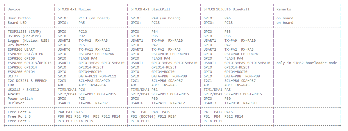
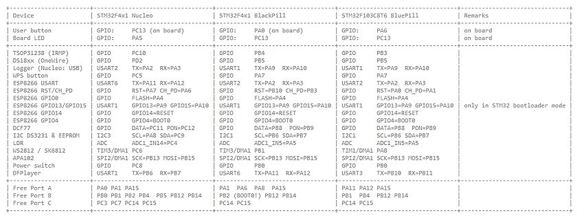
PB9 | GPIO DATA=PB8 PON=PB9 | | * | I2C DS3231 & EEPROM | I2C3 SCL=PA8 SDA=PC9 | I2C1 SCL=PB6 SDA=PB7 | I2C1 SCL=PB6 SDA=PB7 | | * | LDR | ADC ADC1_IN14=PC4 | ADC ADC1_IN5=PA5 | ADC ADC1_IN5=PA5 | | * | WS2812 / SK6812 | TIM3/DMA1 PC6 | TIM3/
-
PDF
TM56M152A-tenxtechnology.pdf
PWM4O/TM0CKI I/O TM0CKI 13 13 11 8 6 PA0/ADC0/PWM5O/PSDA I/O Programming 14 14 12 7 5 PA1/ADC1/PWM1O/INT1/PSCL I/O Programming 15 15 13 9 7 PA3/ADC3/PWM2O/INT0 I/O 16 16 14 10 8 VSS P 1 1 1 1 1 VCC P DS-TM56M152A_E 15 Rev 0.96, 2024/05/16 TM56M152A
in „MCU identifikation/Datenblatt - MC9989A0ZQ“ · Mikrocontroller und Digitale Elektronik ·
-
PDF
TM56E6422-tenxtechnology.pdf
6 19 PA0/ADC0 /PWM5O/CIN2 I/O 18 14 12 5 20 PA1/ADC1 /PWM1O/INT1/CIP1 I/O 19 15 13 7 1 PA3/ADC3 /PWM2O/INT0/CIN I/O 1 16 14 8 4 VSS P DS-TM56E6422_E 13 Rev 0.9, 2024/04/10 TM56E6422 Data Sheet FUNCTION
in „MCU identifikation/Datenblatt - MC9989A0ZQ“ · Mikrocontroller und Digitale Elektronik ·
-
PDF
ADC0801_05.pdf
Applications (Continued) D A 4 Analog Self-Test for a System 8 0 D A 3 8 0 D / 2 8 0 D / 1 8 0 D A DS005671-36 A Low-Cost, 3-Decade Logarithmic Converter DS005671-37 *LM389 transistors A, B, CLM324A quad op amp www.national.com 14 D C Typical Applications (Continued) 0 0 / 3-Decade Logarithmic A/D Converter
in „Verständnisfrage zum ADC080x (VIN-MIN/DC-Offset)“ · Analoge Elektronik und Schaltungstechnik ·
-
PDF
WC_MiniDev_Shield_v6.pdf
4,7uF 1 4 4 > GND 4 SPK_1 IO_2 A DS1820 1 0 1 2 X1-2 UART GND R 1 1 GND_1 GND_2 Power 2 SPK_2 IO_1 LED Power GND GND GND GND JP14 SPK GND IC1 mit LDR: R1 bestücken mit TSOP: R5, C1 bestücken VB 1 40 STM32_3V3_2 R2 frei lassen R16 frei
-
PDF
DS1220Y.pdf
ofCC . 12. WR1 , DH1 are measured from WE going high. 13. WR2 , DH2 are measured from CE going high. 14. DS1220Y modules are recognized by Underwriters Laboratories (UL) under file E99151 (R). DC TEST CONDITIONS AC TEST CONDITIONS Outputs open. Output Load: 100pF + 1TTL Gate All voltages are referenced
in „[S] DALLAS DS1220Y-150 NVRAM (NOS)“ · Analoge Elektronik und Schaltungstechnik ·
-
PDF
_PIC16F176X-7X.pdf
PIC16(L)F1773/6 Data Sheet, DS40001810 CPU High-Endurance Flash Data Gemory-bit & 10-bit DAC (Up to 4 each) 149 Total Instructionsth 100 K Erase / Write CycLes High-Speed ■■ PIC16(L)F1777/8/9 Data Sheet, DS40001819 A Comparators (Up to 8) A ■■ Focus Product Selector Guide, DS00001308 (Up to 100 mA)/Os ■■ Quick Guide to Microchip Development Tools, BOR, WDT, LBPOR, POR, XLP DatUp to 2 KBRAM) Op Amps (Up to 4) DS50001894 Ramp Generator (Up to 4) Links DIGITAL PERIWith PERIPHERAL
in „Wie im Bereich von 1,2Vdc - 117Vdc einstellbare Konstantspannung aus 20Vdc erzeugen?“ · Mikrocontroller und Digitale Elektronik ·
-
 Bild
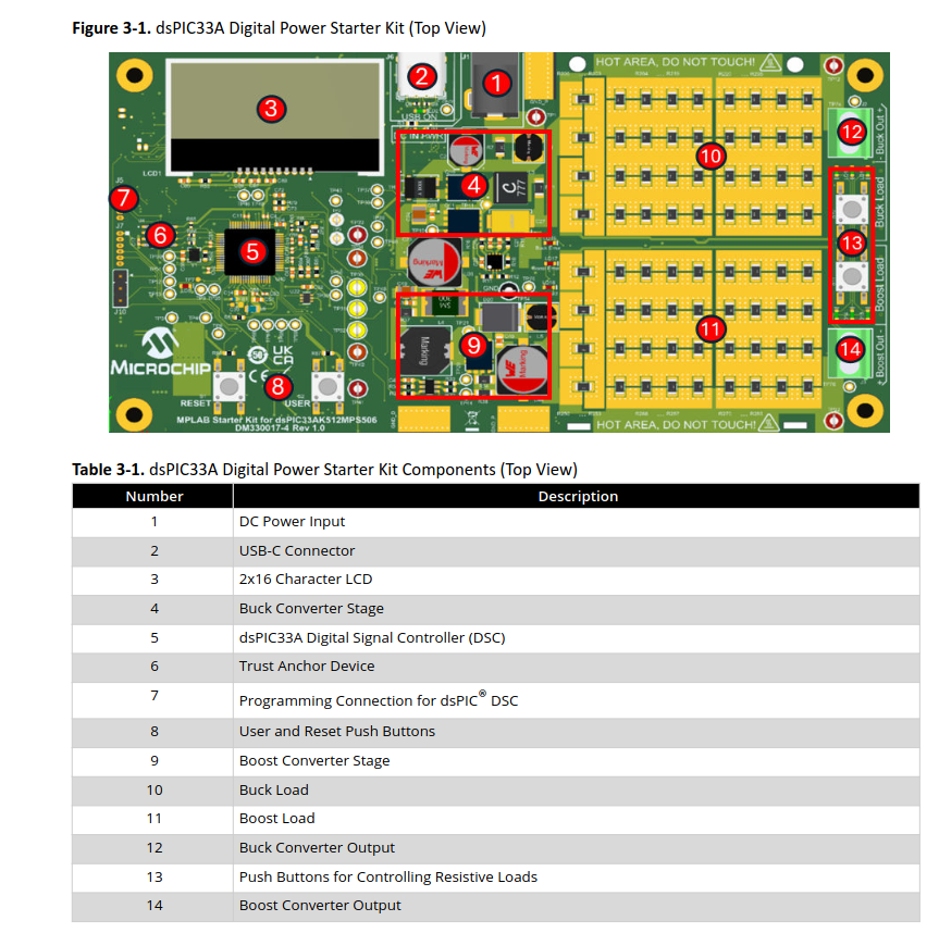
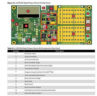
dsPIC33A Digital Power Starter Kit mit Komponentenliste
Figure 3-1. dsPIC33A Digital Power Starter Kit (Top View) 1 2 3 4 5 6 7 8 9 10 11 12 13 14 HOT AREA, DO NOT TOUCH! LCD1 Buck Converter Stage Buck Load Boost Load Buck Converter Output Push Buttons for Controlling Resistive Loads dsPIC33A Digital Signal Controller (DSC) Trust Anchor Device Programming Connection for dsPIC DSC User and Reset Push Buttons MPLAB Starter Kit for dsPIC33A912MPS506 DM30017-4 Rev 1.0 Table 3-1. dsPIC33A
in „Neue Bauteile: vom Radar bis zum Widerstand“ · Mikrocontroller und Digitale Elektronik · · Screenshots
-
PDF
TF5000CI.pdf
ordering information. Pinout CD54HC164, CD54HCT164 (CERDIP) CD74HC164, CD74HCT164 (PDIP, SOIC) TOP VIEW DS1 1 14 VCC DS2 2 13 Q 7 Q 3 12 Q 0 6 Q1 4 11 Q5 Q2 5 10 Q 4 Q3 6 9 MR GND 7 8 CP CAUTION: These devices are sensitive to electrostatic discharge. Users should follow proper IC Handling Procedures. Copyrigh
in „CPU SAA7219 per Jtag auf Basis FT2232H ansprechen - Tool schreiben“ · PC Hard- und Software ·
-
PDF
40146F.pdf
1, transmit seed immediately. 10 1 0 1 0 A B 11 1 0 1 1 A B 12 1 1 0 0 A (1) B 13 1 1 0 1 A (1) B 14 1 1 1 0 A B (1) 15 1 1 1 1 A B (1) Note 1: IR mode © 2011 Microchip Technology Inc. DS40146F-page 11 HCS361 4.0 TRANSMITTED WORD 4.2 Code Word Organization 4.1 Transmission Format (PWM) The HCS361 transmits
in „Fehlersuche Funksender Zentralverriegelung Toyota Yaris“ · Fahrzeugelektronik ·
-
 Bild
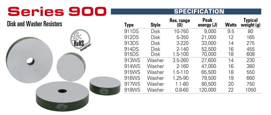
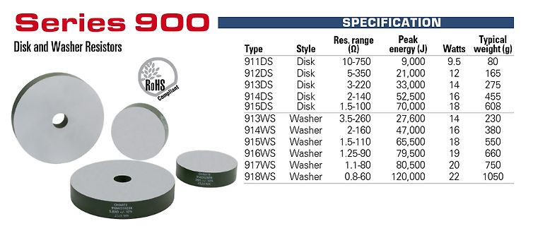
Spezifikationstabelle für Series 900 Disk und Washer Resistors
RoHS Compliant SPECIFICATION Type Style Res. range (Ω) Peak energy (J) Watts Typical weight (g) 911DS Disk 10-750 9,000 9.5 80 912DS Disk 5-350 21,000 12 165 913DS Disk 3-220 33,000 14 275 914DS Disk 2-140 52,500 16 455 915DS Disk 1.5-100 70,000 18 608 913WS Washer 3.5-260 27,600 14 230 914WS Washer
in „Neue Bauteile – kleine Relais, nicht durchbrennende LED-Serienschaltungen und Co“ · Analoge Elektronik und Schaltungstechnik · · Screenshots
-
 Bild
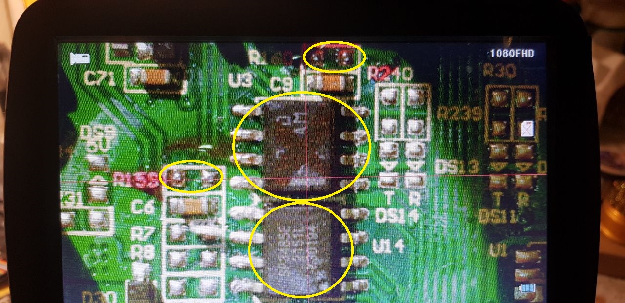
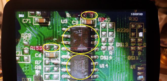
Mikroskopische Aufnahme einer Leiterplatte mit Bauteilen
C71 U3 C9 R240 R30 DS9 R239 DS13 R155 C6 DS14 R7 R8 U14 DS11 R8 U1 1080FHD
in „ALLPOWERS S2000 PRO Reparaturhilfe“ · Mikrocontroller und Digitale Elektronik · · Fotos
-
PDF
MCP1640.pdf
converter, the EN voltage must be less than 20% of the V voltage. IN 2011 Microchip Technology Inc. DS22234B-page 13 MCP1640/B/C/D NOTES: DS22234B-page 14 2011 Microchip Technology Inc. MCP1640/B/C/D 5.0 APPLICATION INFORMATION 5.3 Input Capacitor Selection The boost input current is smoothed by the
in „ESP32-C6 an 18650 Akku betreiben“ · Mikrocontroller und Digitale Elektronik ·
-
Datei
index.html
); chartData.esp32.push(parseFloat(data.internal) || 0); chartData.ds18.push(parseFloat(data.ds18b20) || 0); chartData.scd_t.push(parseFloat(data.scd_temp) || 0); chartData.bme_t.push(parseFloat(data.bme_t) || 0); // Limit to MAX_POINTS (remove from LEFT side) if (chartData.esp32
-
PDF
VRE104c_Thaler.pdf
14-PIN HYBRID INCHES MILLIMETER INCHES MILLIMETER PACKAGE DIM MIN MAX MIN MAX DIM MIN MAX MIN MAX E .480 .500 12.1 12.7 A .120 .155 3.0 4.0 L .195 .215 4.9 5.4 Q .015 .035 0.4 0.9 D .775 .805 19.7 20.4
in „[V] Referenzspannungsquellen VRE Thaler Corp.“ · Markt ·
-
PDF
Viper12a.pdf
Symbol Parameter Test conditions Min Typ Max Unit G ID IFBto D current gain (See Figure 12 on page 14) 320 Dlim Peak current V FB= 0 V 0.32 0.4 0.48 A limitation (See Figure 12 on page 14) FBsd IFBshutdown current (See Figure 12 on page 14) 0.9 mA R FB pin input ID = 0 mA 1.2 kΩ FB impedance (See Figure
in „Reparatur Netzteil elektrischer Kamin“ · Analoge Elektronik und Schaltungstechnik ·
-
PDF
VRE119_Thaler.pdf
RESOLUTION SERVO SYSTEMS • EXCELLENT LINE REGULATION: 3 ppm/V Typ. • DIGITAL VOLTMETERS • HERMETIC 14-PIN CERAMIC DIP • HIGH PRECISION TEST and • MILITARY PROCESSING OPTION MEASUREMENT INSTRUMENTS DESCRIPTION VRE117 Series Precision Voltage References provide ultrastable +3.000V (VRE117), -3.000V SELECTION
in „[V] Referenzspannungsquellen VRE Thaler Corp.“ · Markt ·
-
PDF
technical.pdf
V Th)2 (11.166) gm = β · (1 + λDS )(VGS − VTh) (11.167) γ gmb= g m √ (11.168) 2 Φ − VBS • linear region:DS < VGS − VTh Id= β · (1 + λDS ) · GS − VTh − VDS /2) ·DS (11.169) gds= β · (1 + λDS ) · GS − VTh − VDS ) + β ·λDS · (GS − VTh −
-
PDF
infineon-bsb056n10nn3-g-datasheet-en.pdf
BSB056N10NN3 G Diagram 9: Drain-source on-state resistance Diagram 10: Typ. gate threshold voltage 14 4.0 3.5 12 3.0 10 1000 µA 2.5 ] 100 µA 8 ] m 98 % [ ) t 2.0 ( S D 6 typ G R V 1.5 4 1.0 2 0.5 0 0.0 -60 -20 20 60 100 140 180 -60 -20 20 60 100 140 180 T j°C] Tj[°C] R DS(on)f(Tj; D =30 A; VGS10 V VGS
in „Bauteilsuche Mosfet“ · Analoge Elektronik und Schaltungstechnik ·
-
PDF
RTK_031.pdf
GPS); Wiring inside telecommunications and electronic equipment such as portable phone. RTK-031 1.5DS-QFB / 2.5DS-QFB / 3.5D-QFB Inner Conductor (BC) 1.5DS-QFB Outer Conductor 1(Al-PET-Al) Jacket (PVC) Outer conductor 2 (Copper wire orTinnedCopper wire) Outer conductor 2 Jacket (PVC) (Copper foil tape
in „Suche passenden RP SMA Stecker zum crimpen“ · Mechanik, Gehäuse, Werkzeug ·
-
 Bild
Tabelle mit Pinbelegungen verschiedener Mikrocontroller-Boards
GPIO15=PA10 | USART1: GPIO13=PA9 GPIO15=PA10 | only in STM32 bootloader mode ESP8266 GPIO | GPIO: GPIO14=RESET | GPIO: GPIO14=RESET | USART1: GPIO14=RESET | ESP8266 GPIO | GPIO: GPIO0=BOOT0 | GPIO: GPIO0=BOOT0 | GPIO: GPIO4=BOOT0 | DCF77 | GPIO: DATA=PC11 PON=PC12 | GPIO: DATA=PB6 PON=PB9 | GPIO: DATA=PB8 PON=PB9 | I2C DS3231 & EEPROM | I2C3: SCL=PB8 SDA=PB9 | I2C1: SCL=PB6 SDA=PB7 | I2C1: SCL=PB6 SDA=PB7 | ADC | ADC: ADC1_IN1=PC
in „WordClock mit WS2812“ · Projekte & Code · · Screenshots
-
PDF
Micrel.pdf
2-14: MIC2915x Load Transient. FIGURE 2-17: MIC2915x Line Transient. FIGURE 2-18: MIC2915x Line Transient. FIGURE 2-15: MIC2915x Load Transient. 2016-2019 Microchip Technology Inc. DS20005685B-page 11 MIC2915X
-
PDF
DS-Type-S-SZ-Mersen_2.pdf
107 10 1,0 10210025054 g r . e e M 2 2 © Capacitors / DS-Type-S-01-2024_EN MERSEN.COM CA 89 Type S/SZ ELECTROLYTIC Central Mounted Capacitors CAPACITORS ELECTRICAL DATA AND ORDERING CODE FOR SERIES SZ Rated Ratedcap. Casesize Typ.ESR tan δ RipplecurrentIR~
in „Elko rauh in AEG-Stroboskop von 1955 ersetzen“ · Analoge Elektronik und Schaltungstechnik ·
-
Datei
BME280.c
Langemann mailto: Manfred.Langemann@t-online.de Begin of project: 09.08.2026 Latest version generated: 14.08.2026 Filename: BME280.c Description: Functions for performing BME280 measurements: - Air Pressure in hPa - Temperature in deg C * 10 - Humidity in %RH It uses the AZ-Delivery GY-BME280 board, bought
in „BME280 Sensor - Code für ATmega328 in C“ · Projekte & Code ·
-
PDF
ISL88731.PDF
DACS 5 0 = Adds 0mA of input current. 1 = Adds 8192mA of input current, 11004mA max. 13 Not used. 14 Not used. 15 Not used. FN9258 Rev 3.00 Page 14 of 22 June 8, 2011 ISL88731 Charger Timeout Acknowledge). The master will then produce a Stop condition to end the read transaction. The ISL88731 includes
in „Chip gesucht“ · Mikrocontroller und Digitale Elektronik ·
-
PDF
Daten_vom_CM1051.pdf
wenn die anderen vier Zellen erst bei 3,8 V stehen. Das Pack wirkt dann "schwach". Für den CM1052-DS von iCM gelten die für klassische Kobalt-basierte Lithium-Ionen-Zellen (z.B. LiCoO2, NCM, NCA mit 4,2 V Nennspannung) typischen Werksschwellen. Das Suffix "-DS" definiert dabei das spezifische Spannungsprofil
in „Einhell elektronik vom 18V Akkupack reparieren?“ · Analoge Elektronik und Schaltungstechnik ·
-
PDF
Reparaturanleitung.pdf
wodurch der Entwicklung U3 12 Zeitkondensatorkreis von der Startschaltung getrennt wird. –(11-9) – 13,5–14,5 T1 (11-9) – 12 13,5–14,5 – Der Kondensator entlädt sich über den im Stromstabilisatorkreis T2 angeschlossenen Transistor T29-U3. Die Entladerate des (10,5-11,5) – –(10,1–11,1) – (11,0–10,4) – T3 (18
in „Altes Oszi aus USSR (C1-94). Strahlrücklauf sichtbar.“ · Analoge Elektronik und Schaltungstechnik ·
-
PDF
ErklearungDriverSimulation.pdf
Application Maestro, CodeGuard, devices in life support and/or safety applications is entirely at dsPICDEM, dsPICDEM.net, dsPICworks, dsSPEAK, ECAN, the buyer’s risk, and the buyer agrees to defend, indemnify and ECONOMONITOR, FanSense, In-Circuit Serial hold harmless Microchip from any and all damages
in „Spice Simulation von Treiber TC4229“ · Analoge Elektronik und Schaltungstechnik ·
-
PDF
Bauteile.pdf
11 Mos-Fet W5NB90 900V 9,7S 1Ω 282 12 74xxxx 74150N Multiplexer 13 13 RAM BS62LV256SCP70 8BitRAM 18 14 Triac BT136-600 600V 25A 1661 15 ShuntWiderstand R068 68mΩ 1% 82 16 Optokoppler SFH620A-3 5,3kV Pin 99 17 DualKomparator LM393 SMD 17 Treiber IR327 150 19 IGBT IRG4PH30K 720V 10A TO-247 106 20 Mos-Fet
in „Elektronik Bauteile Neuwertig , meist Leistungselektronik“ · Markt ·
-
PDF
OB2502.PDF
resistance OB2502RCP-H 3.3 Ώ OB2502TCP-H 2.2 Ώ ©On-Bright Electronics Confidential Datasheet OB_DOC_DS_2502xA2 - 5 - OB2502x High Precision CC/CV Primary-Side Power Switch CHARACTERIZATION PLOTS VDD vs Istatic 800 ) 700 u 600 i 500 a 300 I 200 100 0 2 4 6 8 10 12 14 16 18 20 22 VDD(V) UVLO_7(ON)(V) vs
in „SNT Gartenbeleuchtung defekt, pulst aber“ · Analoge Elektronik und Schaltungstechnik ·
-
PDF
pH4502.pdf
durchschnittliche Steigung pro pH = 0,1263 2. Der reale Nullpunkt bei pH 7,00 0,645 V = pH 6,86 + 0,14 pH = pH 7,00 = 0,645 V – (0,14 x 0,1263) = 0,6273 V. {{ (7.0 - ((states('sensor.phpool_voltage_l1 ') | float(0) - 0.6273) / 0.1263)) | round(2) }} 2. Formular für LibreOffice Calc / Excel Hier ist die
in „Automatisierte Ozon-Wasseraufbereitung für Whirlpool“ · Haus & Smart Home ·
-
PDF
Bauteile.pdf
32Polig 126 12 Bauteil Dioden STTH8 600V 8A SMD- 47 13 Bauteil Dioden BYV52IP200 50A Bedrahtet 11 14 Bauteil DualKomparator LM393 SMD 15 Bauteil EEPROM 93LC46A 1KSerielEEPROM 50 16 Bauteil EEPROM 93LC46A 1KB,Seriell 50 17 Bauteil Feinsicherung 250 V 4,0A Flink PE10St. 40 18 Bauteil Feinsicherung 250
-
 Bild
Elektronischer Schaltplan
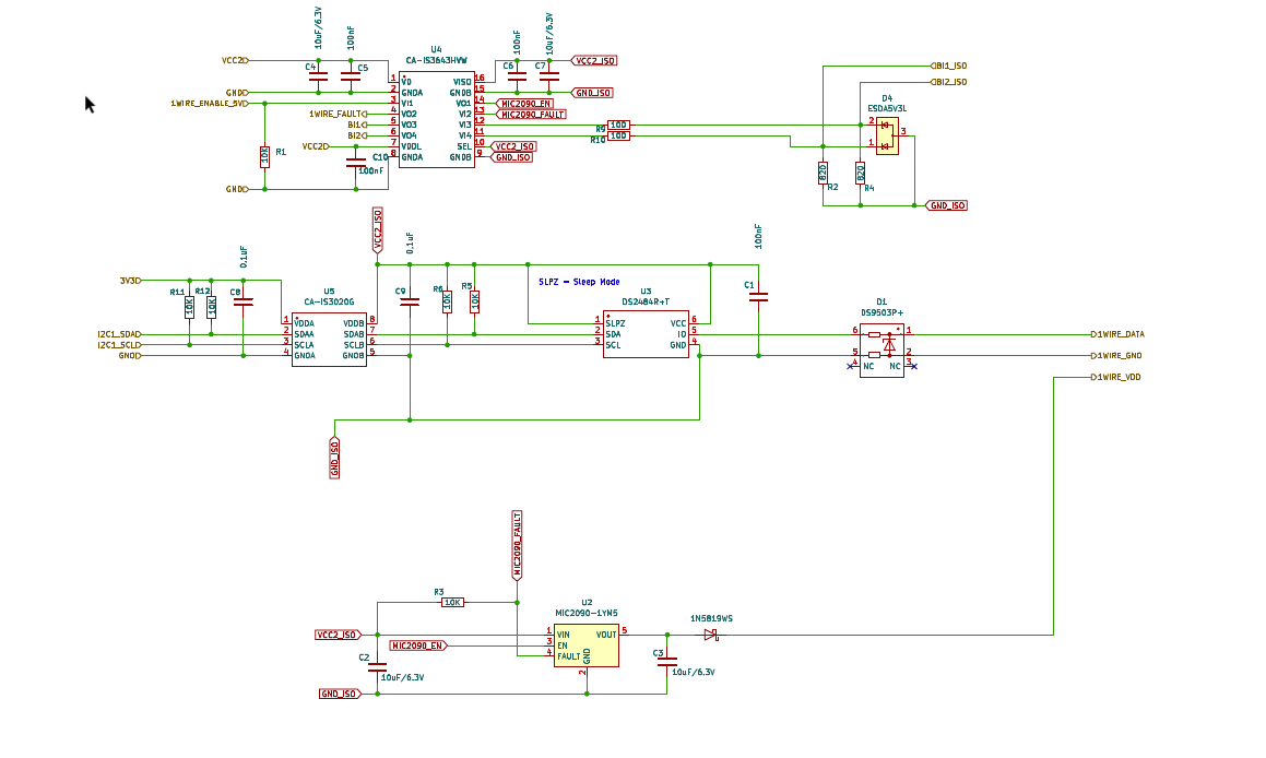
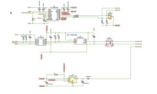
VCC2, ISO, 10uF/6.3V, C5, U4, CA-IS63A3HW, GND, VIS0, GNDA, GND, VDD, VDD, V12, V14, VOA, VOB, SA, GND, 100nF, C10, R1, R2, D4, DS9503V3L, C1, 100nF, U3, SLPZ, DS9503P+, D1, SLPZ, SCL, SDA, SCL, SDA, GND, GND, VDD, D1_WIRE_DATA, D1_WIRE_GND, D1_WIRE_VDD, R3, 10K, MIC2090_FAULT, U2,
in „Frage zu DC/DC Konverter Schaltung“ · Analoge Elektronik und Schaltungstechnik · · Schaltpläne
-
 Bild
Software Update Liste mEDBG_TP nEDBG_TP
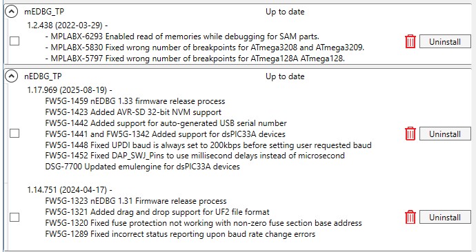
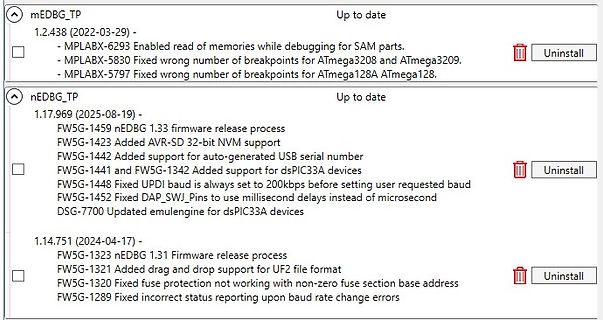
-1442 Added support for auto-generated USB serial number FW5G-1441 and FW5G-1342 Added support for dsPIC33A devices FW5G-1448 Fixed UPDl baud is always set to 200kbps before setting user requested baud FW5G-1452 Fixed DAP_SWJ_Pins to use millisecond delays instead of microsecond DSG-7700 Updated emulgine for dsPIC33A devices 1.14.751 (2024-04-17) - FW5G-1323 nEDBG 1.31 Firmware release process FW5G-1321 Added drag and drop support for UF2 file format FW5G-1320 Fixed fuse protection not working with non-zero
in „ATtiny416-Xplained Nano, Firmware Update“ · Mikrocontroller und Digitale Elektronik · · Screenshots
-
PDF
vt6k1.pdf
.> Parameter Symbol Min. Typ. Max. Unit Conditions Gate-source leakage IGSS - - 10 A VGS8V, V =0DS Drain-source breakdown voltage V 20 - - V I =1mA, V =0V (BR)DSS D GS Zero gate voltage drain current IDSS - - 1 A VDS20V, V =0GS Gate threshold voltage VGS (th) 0.3 - 1.0 V VDS10V, I =D00A - 2.5 3.5 ID=100mA, V =GS5V - 3.0 4.2 I =100mA, V =2.5V Static drain-source on-state D GS R DS (on) - 3.8 5.3 ID=50mA, V =GS8V resistance - 4.5 9.0 ID=20mA, V =GS5V - 6.0 18.0 ID=10mA, V =GS2V Forward transfer admittance l Y l * 180 - - mS V =10V, I =100mA fs DS D Input capacitance C iss - 7.1
in „Bitte um Hilfe Bauteilsuche“ · Analoge Elektronik und Schaltungstechnik ·
-
PDF
device.pdf
DS1216E (8K*8) NONE No Need WMEM1 V5.90 DALLAS EEPROM/FLASH/NVRAM DS1216F (32K*8) NONE No Need WMEM1 V5.90 DALLAS EEPROM/FLASH/NVRAM DS1216F (8K*8) NONE No Need WMEM1 V5.90 DALLAS EEPROM/FLASH/NVRAM DS1220AB
-
PDF
AM700_SM.pdf
DS8 DS5 DS2 DS6 DS13 DS9 DS10 DS11 DS12 +22 +16.5 +15 +14.4 +5 -14.4 -15 -22 OT OV UV OI Figure 6–2: Power supply status indicators for the CRT display power supply GreenLEDnormalvoltageindicators RedLEDerrorindication DS4 DS3 DS8 DS5 DS2 DS6 DS9 DS10 DS11 DS12 +16.5 +15 +14.4 +5 -14.4 -15 OT OV UV OI Figure 6–3: Power supply status indicators for the flat panel display power supply AM700 Audio Measurement Set Service
in „Tektronix AM700“ · Mikrocontroller und Digitale Elektronik ·
-
PDF
innoswitch3-ep_family_datasheet.pdf
R DS(ON)cross temperature for a gate voltage of 4.5 V. There is a slight delay between the commencement of the flyback cycle and the turn-on of the SR FET. During this time, the body diode of the SR FET conducts
in „Fritz Repeater 2400“ · Analoge Elektronik und Schaltungstechnik ·
-
PDF
EA8252.pdf
voltage range. Built-in low R high/low side Power-MOSFETS not only reduce external components and has DS(ON) up to 95% efficiency, ideal for 2A output current applicatiThe EA8252 is designed to take into account the light load mode operation. At output loading 10mA condition, the efficiency up to 81%. The
in „Kurioser DC-DC Step Down Converter“ · Analoge Elektronik und Schaltungstechnik ·
-
 Bild
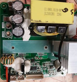
Nahaufnahme einer Leiterplatte mit Transformator und Kondensatoren
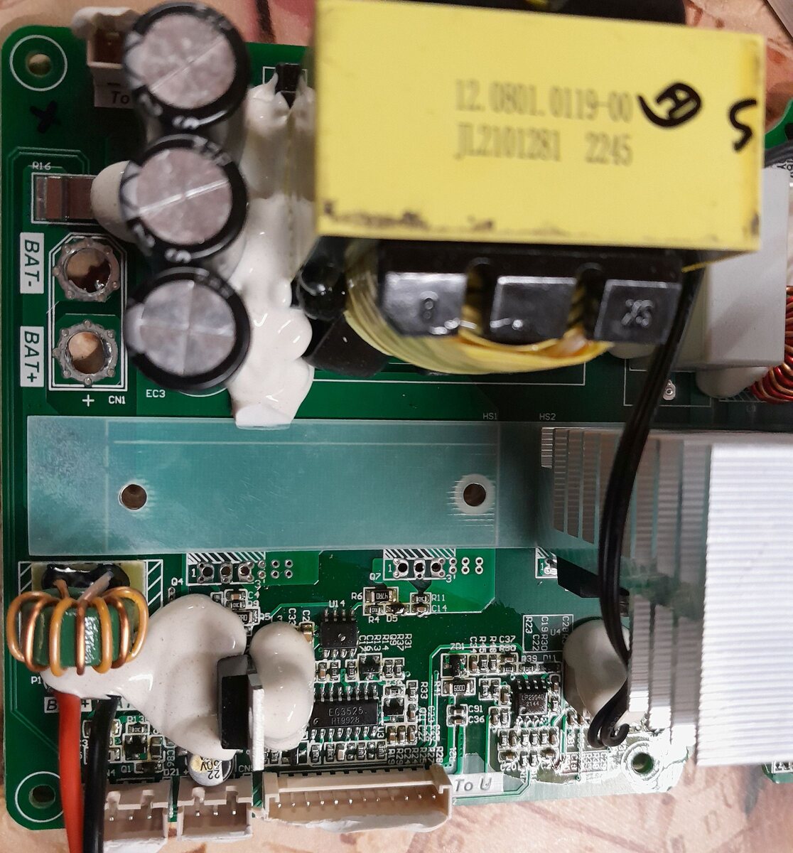
To BAT- BAT+ EC3 CN1 HS1 HS2 12.0801.0119-00 JL2101281 2245 U14 R6 R11 R4 DS C14 R22 R23 R25 R26 R27 R28 R29 R30 R31 R32 R33 R34 R35 R36 R37 R38 R39 R40 R41 R42 R43 R44 R45 R46 R47 R48 R49 R50 R51 R52 R53 R54 R55 R56 R57 R58 R59 R60 R61 R62 R63 R64 R65 R66 R67 R68
in „PDP8974 Ersatz gesucht“ · Analoge Elektronik und Schaltungstechnik · · Platinenfotos