-
PDF
TF5000CI.pdf
_1DS B 63DNG 61Y R 21CA 9ATAD_1DS 53DNG 21Y 8ATAD_1DS T 43DNG 21BA 7ATAD_1DS 33DNG 8Y 11CA 6ATAD_1DS S 23DNG 4Y . 11BA 5ATAD_1DS 13DNG 32V 3 01BA 9 1V + 01AA 4ATAD_1DS 3 03DNG 02T 01Y 3ATAD_1DS 92DNG 4T 9BA 2ATAD_1DS 82DNG 32P V 7BA 1ATAD_1DS M 72DNG 1P 6 7AA 0ATAD_1DS 62DNG 02 M F I 52DNG 4 M 3 0 41SSERDDA_1DS 42DNG 2 2 22AA 31SSERDDA_1DS 32DNG 32K V C + 2 32BA 21SSERDDA_1DS 22DNG 1K 1 22CA 11SSERDDA_1DS 12DNG 02H
in „CPU SAA7219 per Jtag auf Basis FT2232H ansprechen - Tool schreiben“ · PC Hard- und Software ·
-
PDF
MCAC75N06YBTP-datasheet-3.pdf
60 V Gate-Source Leakage Current GSS V DSV, V GS=±20V ±100 nA Zero Gate Voltage Drain Current DSS V DS8V, V =GS 1 µA Gate-Threshold Voltage V V =V , I =250µA 2 4 V GS(th) DS GS D Drain-Source On-Resistance R DS(on) V GS0V, I D20A 5 6 mΩ Diode Characteristics Continuous Body Diode Current S 75 A Diode
in „Suche Ersatz für obsoleten MOSFET MCAC75N06YB-TP (oder Bezugsquelle)“ · Analoge Elektronik und Schaltungstechnik ·
-
PDF
40146F.pdf
PIC16F5xx), midrange and source code for examination and modification. (PIC12F6xx, PIC16F), PIC18F, PIC24, dsPIC30, Theboardssupportavarietyoffeatures,includingLEDs, dsPIC33, and PIC32 families of 8-bit, 16-bit, and 32-bit temperature sensors, switches, speakers, RS-232 microcontrollers, and many Microchip Serial
in „Fehlersuche Funksender Zentralverriegelung Toyota Yaris“ · Fahrzeugelektronik ·
-
PDF
DM8603EP.pdf
Ethernet Switch Controller with MII / RMII Interface DATASHEET Preliminary Datasheet Version: DM8603-DS-P01 November 8, 2010 Preliminarydatasheet 1 DM8603-12-DS-P01 November8,2010 Downloaded from Elcodis.com electronic components distributor DM8603 10/100Mbps3-portEthernetSwitchControllerwithMII/RMIIInterface
in „[V] DM8203 & DM8603“ · Markt ·
-
PDF
53131a_53132a_bedienungsanleitung_deutsch_komprimiert.pdf
usgangsssignals eingerichttet. D rift t ein Meßwerrt au dem be dieners ezifizierten Grenzbereich,, Ieuchttet ds Anzeigefeld Limit au dem Dis play auf. Außerdem än t S tit4 am RS-2322-Anschluß se inen tatus dert nnungspegel) S tus (aufeinen niedrigenn R S-232- Spa spe gel) und sgnallisiert dait ale M eßwertdriftss
in „[V] HP/Agilent 53131a/53132a Bedienungsanleitung deutsch“ · Markt ·
-
Datei
BME280.c
github.com/finitespace/BME280 The calibration algorithm is based on the Bosch documentation BST-BME280-DS001-23 Revision_1.23_012022 on page 25 To do single measurements, the code uses the "forced mode". The C code has been implemented on an ATmega328 with a 2 MHz crystal, using the Atmel-Studio 7 To interface
in „BME280 Sensor - Code für ATmega328 in C“ · Projekte & Code ·
-
 Bild
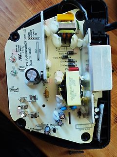
Innenansicht einer Leiterplatte mit Transformatoren und Bauteilen
D03 D04 D01 D02 C5 SILHERL285014NP 2425 SL C11 D10 C12 BAT- C2 BAT+ J7 J8 ( +5V) U7 C20 Date code: DS2425 NW-03 C37405 232Y. 4 US 434Y. 04
in „Milwaukee Ladegerät von 120 auf 240V umbauen“ · Analoge Elektronik und Schaltungstechnik · · Platinenfotos
-
 Bild
Display eines Rigol DS1054Z Oszilloskops mit installierten Optionen
Rigol DS1054Z OSCILLOSCOPE UltraVision 4Channel 50MHz 1GSa/s Installed Options Name Detail Version Left-Time TRIGGER Timeout Official --- Runt Official --- Window Official --- Delay Official --- Setup Official --- NthEdge Official --- RS232 Official --- I2C Official --- SPI Official --- DECODER RS332 Official --- I2C Official --- SPI Official --- MEM-DEPTH 24M/12M/6M Official --- RECORDER Record/Re-Play Official --- *Width***** Fall***
in „[V] RIGOL DS1054Z Oszilloskop“ · Markt · · Fotos
-
PDF
technical.pdf
L) (11.230) Y GB = jω(C GB + C GBOV L) (11.231) YBD = gbd+ jω C BD dep+ CBDS dep+ CBD diff (11.232) YBS = gbs+ jω C BSdep+ C BSSdep+ C BSdiff (11.233) Y = g (11.234) DS ds 11.5.4 Noise model The thermal noise generated by the external resistorG R S and R D is characterized by the following spectral
-
PDF
ISL88731.PDF
Current VDDP = SCL = SDA = 5.5V 20 27 µA V REFERENCE VREF Output Voltage 0 < VREF < 300µA 3.168 3.2 3.232 V ACOK ACOK Sink Current VACOK = 0.4V, ACIN = 1.5V 2 8 mA ACOK Leakage Current VACOK = 5.5V, ACIN = 3.7V 1 µA ACIN ACIN rising Threshold 3.15 3.2 3.25 V ACIN Threshold Hysteresis 40 60 90 mV ACIN Input
in „Chip gesucht“ · Mikrocontroller und Digitale Elektronik ·
-
PDF
AM700_SM.pdf
undervolts) LED is also on in the standby state. GreenLEDnormalvoltageindicators RedLEDerrorindication DS7 DS4 DS3 DS8 DS5 DS2 DS6 DS13 DS9 DS10 DS11 DS12 +22 +16.5 +15 +14.4 +5 -14.4 -15 -22 OT OV UV OI Figure 6–2: Power supply status indicators for the CRT display power supply GreenLEDnormalvoltageindicators RedLEDerrorindication DS4 DS3 DS8 DS5 DS2 DS6 DS9 DS10 DS11 DS12 +16.5 +15 +14.4 +5 -14.4 -15 OT OV UV OI Figure 6–3: Power supply status indicators for the flat panel display power supply AM700 Audio Measurement Set Service
in „Tektronix AM700“ · Mikrocontroller und Digitale Elektronik ·
-
PDF
Sartorius_Waage_Manual_Anleitung_Handbuch_QC7DCE-S.pdf
Your PC interface, i.e. COM1or COM2 (enter1or 2)”; a 1015 IF a = 1 THEN OPEN “com1:1200,o,7,1,CS1000,DS0,CD0,PE” FOR RANDOM AS #1 1016 IF a = 2 THEN OPEN “com2:1200,o,7,1,CS1000,DS0,CD0,PE” FOR RANDOM AS #1 1018 PRINT “” 1019 PRINT ““Sample: Note: Delivery:” 1030 PRINT “Smith and Jones Printed line 1 (
in „Frage zu einer Waage / Sartorius QC7DCE-S“ · Mechanik, Gehäuse, Werkzeug ·
-
PDF
innoswitch3-ep_family_datasheet.pdf
the SR FET drops below zero volts. higher than the regulation threshold, a bleed current of ~2.5 mA DS(ON) (3 mA max) is applied on the OUTPUT VOLTAGE pin (weak bleed). In continuous conduction mode (CCM) the SR FET is turned off when This bleed current increases to ~200 mA (strong bleed) in the event
in „Fritz Repeater 2400“ · Analoge Elektronik und Schaltungstechnik ·
-
Datei
idf_py_stdout_output.txt
[231/1714] Building C object esp-idf/lwip/CMakeFiles/__idf_lwip.dir/port/freertos/sys_arch.c.obj [232/1714] Building C object esp-idf/lwip/CMakeFiles/__idf_lwip.dir/lwip/src/netif/ppp/polarssl/des.c.obj [233/1714] Linking C static library esp-idf/esp_netif/libesp_netif.a [234/1714] Building C object
in „Openocd auf ESP32S3“ · Mikrocontroller und Digitale Elektronik ·
-
PDF
T6963C.pdf
― ns C / D Hold Time CDH ― 10 ― ns CE , RD , WR Pulse Width tCE RD WRt ― 80 ― ns Data Set−up Time tDS ― 80 ― ns Data Hold Time t ― 40 ― ns DH Access Time t ― ― 150 ns ACC Output Hold Time tOH ― 10 50 ns 31 2002-01-07 T6963C ● Switching Characteristics (3) (1) External RAM Read mode (2) External RAM Write
in „altes Phytec MCB-51 Monitor/Basic Befehle?“ · Mikrocontroller und Digitale Elektronik ·
-
PDF
fla-203.pdf
400 393 407 14.4 14.1 14.7 16 1600 1600 1581 1619 57.6 56.9 58.3 32 6400 6400 6333 6467 230.4 227.9 232.8 Adapter cable connection P200 input U-R-F P200 settings - URFIT - Multi-signal - AC sine-wave/square-wave signal: Alternating voltage (Uss): see table Frequency: see table Type: sine 10 Adapter cable
in „Kommunikation mit Leistungsprüfstand BOSCH FLA203“ · PC Hard- und Software ·
-
PDF
pm2519ocr.pdf
e s e e e s e2n4 2 B N General e e e e e e e e v e r e e r e c t rete et teen een een eee e ns B f 232, Analog section... eevee cece eee eeceeee een eee eee eee eee e ese 24 2.3.2.1. DC voltage m e a s u r e m e n t so.e .e.e e cece cence eee ee ee ee tence eens 2M 23.2.2. Alternating voltage measurements
in „Pjilips PM2519“ · Markt ·
-
PDF
PMT_handbook_v4E.pdf
....231 12.3 Various Characteristics of HPD........................................................232 12.3.1 Pulse height resolution........................................................232 12.3.2 Gaincharacteristicsandelectronbombardment gainuniformity....232 12.3.3 Time response characteristics.
in „Suche nach geeignetem OpAmp als Impedanzwandler“ · Analoge Elektronik und Schaltungstechnik ·
-
PDF
pm2521ocr.pdf
s o o s S a s G 3G o ec> a o > H u ? o f o > oo : S} 2556 2 O a 8 g ) / E S E u x | eZ O o Z v % >>Ds . ¥wa + oo a +1 = G x&) Ong C z sg ® S A C so x® o O= 3 ajeaer a ° S a v iD 1 + |+ea9 s a e s+ 1+ a8 a e ! S 2 8 : S 1 2 6 + a & ye | o s dSRO] c o s B O T + a 0 w e : = 3 ga P o8 2 8 2 , e s l . ! =
in „Pjilips PM2519“ · Markt ·
-
PDF
asus-p701-unlocked.pdf
TACH I VGA FanTach(Unused) 87 PSCLK3 TP_CLK I/OD 10K Pull +3VS 94 GND GND P C 30 GPIO16 E51_TX O RS232 debug port 88 PSDAT3 TP_DAT I/OD 10K Pull +3VS 96 VCC +3VA_EC P C 31 GPIO17 N.C O Reserved 89 GPIO50 BATSEL_3S O Battery series. Hi:3S, 111 VCC +3VA_EC P Lo:4S(Unused) 32 GPIO18 PWR_SW# I power button