Suchergebnisse für "EC11"
Draing configuration (mN・m) detent ofpulse switch No. PackageType (mm) (mm) (cycles) (pcs.) TM 18 9 EC 11 J0920402 TACTSwitch Without 1 30 1 5 EC 11 J1520402 Custom- Products 18 9 EC 11 J0924411 0.5 100,000 30 1 5 EC 11 J1524413 18 9 W ith 2 1.5 EC 11 J0925403 30 15 EC 11 J1525402 18 9 EC 11 J0920602 Without 1 30 15 EC 11 J1520602 Reflow Flat 20 18 9 0.5 500,000 600 EC 11 J0924602 Metal 12±5 30 15 EC 11 J1524604 Shaft With 2 18 9 EC 11 J0925602 Insulated 1.5 Shaft 30 15 EC 11 J1525602 Hollow 18 9 EC 11 J0920802 Shaft 30 15 Without
in
„Encoder für Hameg HMO3522“
·
Platinen
·
22.07.2026 18:30
:203080002299105AD70DB1FF1CC701F6E11 CB1035A2005C701F6E100B05A1CC70100C11 C03 :2030A000BF0100C11 CB31D579C1CC70104C11 CB30100C11 CAF0104C11 EC 71F01C11 CBF0143 :2030C00000C11 CB31D709C1CC70100E21CF0AC5A1CB31DDC221CC70100C11 CBF0100C11 C17 :2030E000B31D579C1CC70104C11 CB30100C11 CAF0104C11 EC 71F01C11 CBF0100C11 CB31DF3
in
„[V] Rohde und Schwarz SMY02 9kHz-2.080Gh Signal Generator“
·
Markt
·
01.04.2026 10:08
vs. temperature Figure 10. Bias current vs. temperature Figure 11 . Supply current vs. temperature Figure 12. Supply current vs. input voltage DocID5257 Rev 12 9/23 Typical application circuit MC34063AB, MC34063AC, MC34063EB, MC34063EC 6 Typical application circuit
in
„Ein passender Widerstand für MC34063“
·
Analoge Elektronik und Schaltungstechnik
·
27.08.2026 07:47
.......10 18、 Packaging Standard...................................................................11 19、 Reliability Test............................................................................12 3/13 Document No.: SPC / SK6803-EC 14-000 Rev. No.:01 东莞市欧思科光电科技有限公司 DONGGUAN OPSCO OPTOELECTRONICS CO
in
„Miniatur Parabolspiegel für Modellbau“
·
Offtopic
·
10.10.2026 15:25
r18, r0 11 e4: 11 24 eor r1, r1 11 e6: 49 81 ldd r20, Y+1 ; 0x01 11 e8: 5a 81 ldd r21, Y+2 ; 0x02 11 ea: 42 0f add r20, r18 11 ec : 53 1f adc r21, r19 11 ee: 4e 87 std Y+14, r20 ; 0x0e 11 f0: 5f 87 std Y+15, r21 ; 0x0f
in
„Bizarrer Firmware crash - ATmega4808. Wie Debuggen?“
·
Mikrocontroller und Digitale Elektronik
·
15.07.2026 17:37
VCC +3VA_EC P 21 PWM1 BL_PWM_DA O LCD Light Switch 81 KSO16 N.C O Reserved 24 GND GND P 23 PWM2 LCD_SCL O LCD clock 82 KSO17 N.C O Reserved 33 VCC +3VA_EC P 25 GPIO11 PM_PWRBTN# OD Power Button to SB, * 83 PSCLK1
in
„ASUS Eee PC 4G 701 Speichererweiterung“
·
Platinen
·
18.12.2025 23:14
3 6-00-0008 ENCODER 1 VR11 3 9-40-0291 MIXER PCB 1 3 BAKCA-04 PCB HOLDER 2 3 BALD40210-0 LED HOLDER 24 LED1~LED24 3 CN0820001101 8P CONNECTOR 110mm 1 TE1 3 EC 10616TS ELECT 10UF/16V(S) 1 C333 3 EC 10625T ELECT 10UF/25V 8 C167,169,172,176,182,184,188,192
in
„Mischpult "Alesis Multimix 8" (Knallen auf allen Ausgängen)“
·
Analoge Elektronik und Schaltungstechnik
·
08.07.2026 21:29
V5=3.5 → 2.0V V1=V2=V3=V4=V5=3.5V, 恢复延时 T ODR 24 48 72 ms V5=2.0 → 3.5V 放电 V1=V2=V3=V4=V5=3.5V, V EC 1 0.005 V EC 1 0.050V VEC1 0.005 保护电压 VEC1 V VINI=0 → 0.12V V EC 1 0.010 V EC 1 0.100V VEC1 0.010 过流 V1=V2=V3=V4=V5=3.5V, 1 保护延时 TEC1 0.5 1.0 1.5 s VINI=0 → 0.12V,C TEC0.1μF 放电 V1=V2=V3=V4=V5=3.5V, 保护电压
in
„Einhell elektronik vom 18V Akkupack reparieren?“
·
Analoge Elektronik und Schaltungstechnik
·
30.09.2026 22:53
voltageto be measured ispassed to thed.c.attenuatorwhere by means of resistors switched by attenuated 11 -11 oF 1111.11 times, The table indicates the attenuation factor for each range, the A D C input The 11 .14 attenuation isachieved with the resistors 1102, R103 and the Ri of the ADC, The 1111.11 1 1 0
in
„Pjilips PM2519“
·
Markt
·
18.04.2026 12:51
- neuer Funk-Schlüssel Manchester I Key 1 256 Bit 64 Hex-Zeichen 32 Byte 0000000000000000000022455e11 ec 27170ebe3167f122af08f6138b875f18b0 ffffffffffffffffffffe24558fff3a1ba0d66d0f7f122ac7ff9d0dd06b36878 ffffffffffffffffffffe2455be894f1c2cd570c07f122adf44a78e166ab8600 80 Bit 10 Byte 20 Hex-Zeichen 0 oder
in
„Funkschlüssel Peugeot Partner I“
·
Fahrzeugelektronik
·
25.03.2026 18:26
löschen............................................................................................10 6.11 Monatswerte (letzter Monat).............................................................................................11 6.11 .1 Auslesen......................................................................................................................11 6.11 .2 Löschen.......................................................................................................................11 6.12 Error Speicher (Error-Log) löschen........................
in
„Wärmezähler über optische M-Bus-Schnittstelle auslesen“
·
Haus & Smart Home
·
13.12.2025 20:55
08004c38 t $d 08004c9c t $d 08004d10 t $d 08004d54 t $d 08004d70 t $d 08004d80 t $d 08004dc4 t $d 08004ec 4 t $d 20000ef0 b $d 20000ef4 b $d 08004ed0 t $d 08004edc t $d 08004f0c t $d 08004f48 t $d 20001034 b $d 08005008 t $d 0800507c t $d 080050a0 t $d 080051f8 r $d 08005234 r $d 08005258 r $d 08005588 r
in
„Warum ist die USB/CDC Implementierung der Cube HAL so groẞ?“
·
Mikrocontroller und Digitale Elektronik
·
07.02.2026 16:06
Motorcaravan - 23-08 - DE 193 -Changedi -XhangeEi PD !r PD !r NW NO UY UY toB toB ww Clk m ww Clk m w.p ec .p e.o fxchang 9 Elektrische Anlage f-chang LEDs 12,5 V und darüber: Batterie geladen LEDs 12,2 V: Batterie teilentladen (unter 12,4 V) Untere 2 LEDs: Batterie leer (unter 11 ,6 V) Die folgenden
in
„Wohnmobil Elektroblock EBL 119 defekt keine Ladung der Barrerie“
·
Analoge Elektronik und Schaltungstechnik
·
21.03.2026 11:11
memory Model of levels number of channels line table mode (XW) protection areas levels Address/ V2A RV32EC 2 2 2 2 Instruction √ × Note: OS task switching generally uses stack push, which are not limited in number of levels. 1.1 Instruction set QingKe V2 series microprocessors follow the standard RV32EC Instruction
in
„CH32V006 und CH32V007 von WCH“
·
Mikrocontroller und Digitale Elektronik
·
14.07.2026 12:10
manuell von 0x3e000 auf 0x1e000 geändert und geflascht, zeigt den schnellen toggler !!! (:020000021000EC statt :020000023000CC) 0003e000 <__ctors_end>: 3e000: 27 9a sbi 0x04, 7 ; 4 3e002: 00 00 nop 3e004: 00 00 nop 3e006: 1f 9a sbi 0x03, 7 ; 3 3e008: 1f 9a sbi 0x03, 7 ; 3 3e00a: 0d 94 07 f0 jmp 0x3e00e
in
„Programmierfehler bei 0x3E000 im ATmega2560, wenn mySmartUSBlight per ISP verwendet“
·
Mikrocontroller und Digitale Elektronik
·
08.10.2026 13:04
CuZn (Messing) Kontaktoberfläche Au (Gold) REACH SVHC CAS 7439-92-1 (Lead) SCIP Nummer 81762dbb-0d8d-4ec 0-a6a8-ce77fa6464dc Klassifikationen eCl@ss 11 .1 27-44-01-09 ETIM 7.0 EC 003569 CE-Konformitätserklärungen Niederspannungsrichtlinie 2014/35/EU (EN 60204-1:2018;EN 60529:1991) Montageanleitung Ausdruck
in
„[V] 17Stück 14-poliger Binder Miniatur Steckverbinder 16mm M16 IP40 Serie 680 (alle 25€)“
·
Markt
·
16.11.2025 20:58
instruments that have been verified by SARTORIUS for use as legal measuring instruments and that have an EC Type-Approval Certificate, see the next page. This Directive also regulates the performance of the EC verification by the manufacturer, provided that an EC Type-Approval Certificate has been issued and
in
„Frage zu einer Waage / Sartorius QC7DCE-S“
·
Mechanik, Gehäuse, Werkzeug
·
03.08.2026 12:19
1.65mm Vibration Resistance Endurance 10 to 55Hz double amplitude 3.3mm Misoperation Min. 100m/s² (11 ± 1ms) Shock Endurance Min. 1000m/s² (6 ± 1ms) Weight Approximately 13 g Sealing Sealed RTIII * 1 When max. carrying current is more than 10A, PCB layout needs to be considered. * 2 Minimum switching
in
„[V] 15 Stück Print Relais F1CA012V (2 Wechsler)“
·
Markt
·
26.04.2026 12:03
Bild
Hardware Devices Rules Notifications Tools
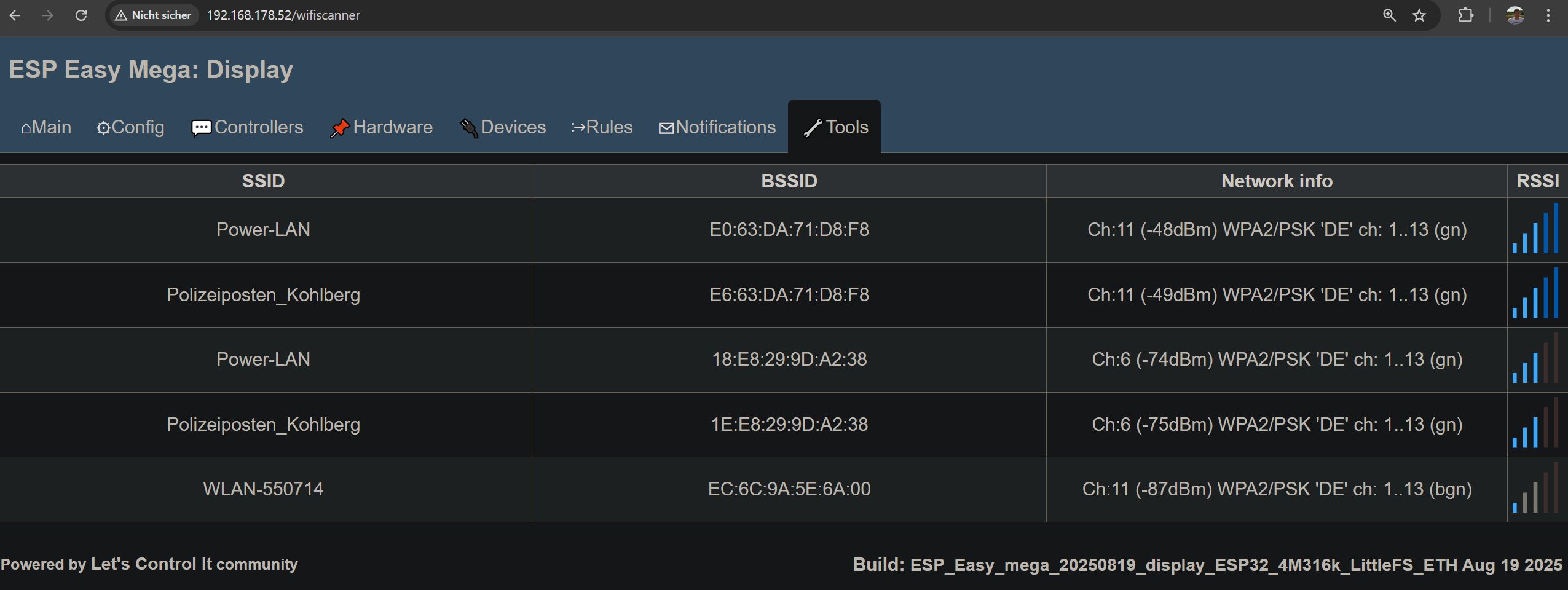
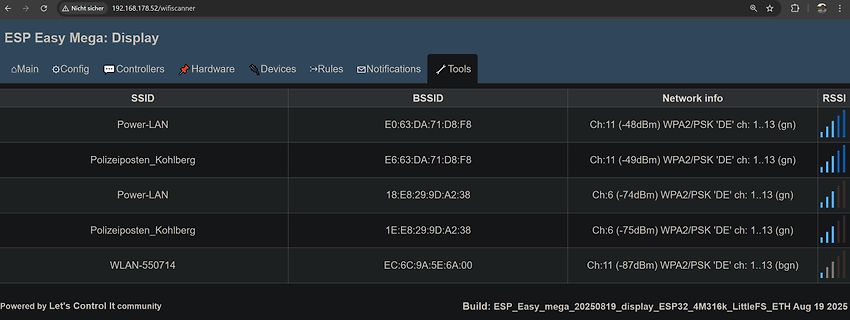
SSID BSSID Network info RSSI
Power-LAN E0:63:DA:71:D8:F8 Ch:11 (-48dBm) WPA2/PSK 'DE' ch: 1..13 (gn)
Polizeiposten_Kohlberg E6:63:DA:71:D8:F8 Ch:11 (-49dBm) WPA2/PSK 'DE' ch: 1..13 (gn)
Power-LAN 1E:E8:29:9D:A2:38 Ch:6 (-74dBm) WPA2/PSK 'DE' ch: 1..13 (gn)
Polizeiposten_Kohlberg 1E:E8:29:9D:A2:38 Ch:6 (-75dBm) WPA2/PSK 'DE' ch: 1..13 (gn)
WLAN-550714 EC :6C:9A:5E:6A:00 Ch:11 (-87dBm) WPA2/PSK 'DE' ch: 1..13 (bgn)
Build: ESP_Easy_mega_20250819_display_ESP32_4M316k_LittleFS_ETH Aug 19 2025
in
„DIY Antenne für WLAN bzw. ESP/Arduiino“
·
HF, Funk und Felder
·
10.01.2026 21:01
·
Screenshots
DOUT PE6 PIE0 PLD1 4PE0 PE6 SMPS 3V3 P6 VDD GND PLE203 PILD30 PLE43 PIED033 P VDD GND GND C6C SK6812D-EC 3210R GND GND GND GND CSK6812D-EC 3210R DC in 0.1 µF GND SK6812MINI-E SK6812MINI-E SK6812MINI-E SK6812MINI-E 0.1 µF GND P6 GND GND GND GND P GND GND LED's 5V IC2 3V3 J2C VBUSB D3 5V PIIC203 VIN VOUT PIIC202
in
„Bitte um Review meiner erweiterten ONYU-Schaltpläne (Bluetooth-Erweiterung mit CSR8635)“
·
Mikrocontroller und Digitale Elektronik
·
29.11.2025 01:45
T1] [cbm] { dma_port_enable : 4670 }10 0x4 [ 1.268154][ T1] [cbm] { reserved_ports_highest : 5161 }11 11 5 21 [ 1.274653][ T1] [cbm] { dma_port_enable : 4670 }11 0x4 [ 1.280217][ T1] [cbm] { reserved_ports_highest : 5161 }12 12 6 22 [ 1.286718][ T1] [cbm] { dma_port_enable : 4670 }12 0x4 [ 1.292282][
in
„FritzBox 7590 Boot Loop“
·
Mikrocontroller und Digitale Elektronik
·
02.12.2025 11:22
Configuration Single • Ease of Paralleling D • Simple Drive Requirements • Compliant to RoHS Directive 2002/95/EC TO-220AB DESCRIPTION Third generation Power MOSFETs from Vishay provide the G designer with the best combination of fast switching, ruggedized device design, low on-resistance and cost-effectiveness.
in
„Aus Minus Plus machen?“
·
Analoge Elektronik und Schaltungstechnik
·
15.07.2026 21:03
(only once). Product Dimensions Common Dimensions (TOP VIEW) (TOP VIEW) (BOTTOM VIEW) (SIDE VIEW) 11 .7 11 .7 5.0 8.1 (.461) 8.1 (.461) 5 PLCS. (.197) 4.5 (.319) (.319) 1.0 (.177) D E D E (.039) (SWORCH DUMMY TERMINALS) 3.0 3.0 (.118) 14.2 (.118) 14.2 2.0 +0.03/-0.05 (.559) (.559) (.079 +.001/-.002) DIA
in
„Encoder für Hameg HMO3522“
·
Platinen
·
22.07.2026 18:30
Equipotential-bonding socket 9 Connecting socket for soldering tool 10 USB interface, B-Mini (WD 1M) 11 Mains connection 12 Mains system fuse 13 Temperature display 14 Temperature symbol 15 Time function 16 Lock 17 Optical control check 18 Temperature buttons 19 Fixed temperature display 20 Special functions
in
„Weller Versorgungseinheit WD1M“
·
Analoge Elektronik und Schaltungstechnik
·
22.09.2026 20:49
: inc Register_30 Address_26F: djnz Register_45,Address_226 ret Address_273: clr P13 clr P10 setb P11 lcall Address_2B0 clr P11 lcall Address_2B0 setb P11 lcall Address_2B0 ljmp Address_29C Address_289: clr P13 clr P10 setb P11 lcall Address_2B0 clr P11 lcall Address_2B0 clr P11 lcall Address_2B0 Address
in
„Eprom von Denon DJ Laufwerk defekt Winbond 78e52“
·
Mikrocontroller und Digitale Elektronik
·
19.12.2025 16:05
CAPACITOR(0.1uF/50V,Z,TAPING,Y5V) 413-3113-035 9 38 C126,C139 ELEC. CAPACITOR(100uF/10V,M,105℃,TAPING 5*11 )(Cd,Pb,Hg,Cr)6 2 C127 ELEC. CAPACITOR(1uF/50V,M,105℃,TAPING 5*11 ,NP)(Cd,Pb,Hg,Cr) 1 C104 ELEC. CAPACITOR(1uF/50V,M,105℃,TAPING 5*11 )(Cd,Pb,Hg,Cr)049 1 C101 ELEC. CAPACITOR(4.7uF/50V,M,105℃,TAPING 5*11
in
„Eprom von Denon DJ Laufwerk defekt Winbond 78e52“
·
Mikrocontroller und Digitale Elektronik
·
19.12.2025 13:42
9D 55 CD 53 FD 58 0E FF 3E FF 6E FF 9E 25 CE 23 FE 28 0F FF 3F FF 6F FF 9F 05 CF 03 FF 08 10 FF 40 11 70 FF A0 FF D0 FF 11 FF 41 41 71 FF A1 FF D1 FF 12 FF 42 FF 72 FF A2 FF D2 FF 13 FF 43 FF 73 FF A3 FF D3 FF 14 FF 44 31 74 FF A4 FF D4 FF 15 FF 45 51 75 FF A5 FF D5 FF 16 FF 46 21 76 FF A6 FF D6 FF 17
in
„Fileformat für EPROM-Programmer“
·
Mikrocontroller und Digitale Elektronik
·
05.06.2026 11:22
Bild
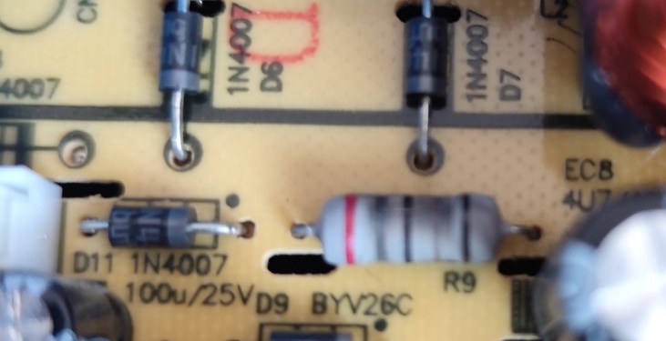
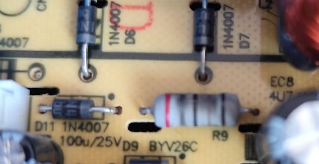
1N4007 D6 1N4007 D7 D11 1N4007 100u/25V D9 BYV26C R9 EC 8 4U7
in
„Sicherungswiderstand identifizieren“
·
Analoge Elektronik und Schaltungstechnik
·
01.10.2026 11:57
·
Platinenfotos
oututBufr(NL0/6) Iput+,7V, eed2 93 +4 _ ~] r o n e Oe s G a 1 bees ee D =+ r c o n n e c t e d Z E=Rz ec o n n e c t e d 9.3 *P=P(N1403/11 )ece +5 V * N (N1403/1)e - refe-5 Vv (4) *Z=Autozro(141/) 93 DCcntol 1e imesl----}-. : eer7se 9.3 *U=Up ADC control/) |Iput+,7V, eed2 ses lin ee“aa nisame wats| ates
in
„Pjilips PM2519“
·
Markt
·
18.04.2026 12:52
Bild
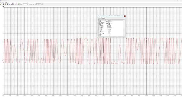
WAVEDATA.EC ... Zoom: 1:1 Waveform File: 2/2 Properties: C:\Users\grizm\OneDrive\ANDROID AG\Desktop\... Item: WAVEDATA... Value: ... ROM Version: V1.17... Function: REAL TIME... Trig Date: 25-11 -08... Trig Time:
in
„Hioki MR8880 Oszilloskop 60hz Spannungsmessung Zeitachse“
·
Analoge Elektronik und Schaltungstechnik
·
26.11.2025 09:36
·
Oszi-Bilder
Bild
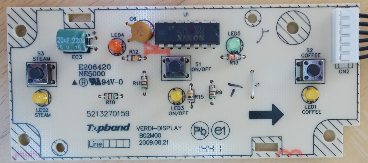
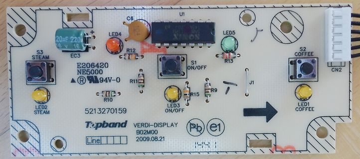
C6 104 U1 LED4 R12 EC 3 20uF 16V 16 S3 STEAM E206420 NE50 R11 S1 ON/OFF LED2 STEAM 5213270159 R15 R9 LED3 ON/OFF J1 LED1 COFFEE S2 COFFEE CN2 Topband VERDI-DISPLAY B02M0 209.08.21 Pb e1
in
„Sporadisches Durchschalten eines TRIACs“
·
Analoge Elektronik und Schaltungstechnik
·
06.09.2026 13:43
·
Platinenfotos
Bild
hotmail.com
Address : lijinchenggongyeyuan7haochangfang2ceng204A
Longhua Street, Shenzhen, Guangdong, China
EC REP eVatmaster Consulting GmbH, Bettinstr. 30, Frankfurt am
Main, Germany contact@evatmaster.com +496995179070
UK REP EVATOST CONSULTING LTD, Suite 11 , First Floor, Moy Road
Business Centre, Taffs Well
in
„ESP32 - merkwürdige Mail von AliExpress“
·
Offtopic
·
24.07.2026 10:35
·
Fotos
Bild
250V 250uF 100uF 100uF J24 M05 RT9 C41 D55 R117 R10 C62 R16 C61 CY1 J7 C40 R41 R10 R11 R30 JP21 JP17 JP16 EC -333/0 2011-03-22 EASEPAL J22 D15 JP2 C17 R74 R77 C12 C13 C18 C19 C20 C21
in
„Ringkerntrafo für Massagesessel gesucht“
·
Analoge Elektronik und Schaltungstechnik
·
02.01.2026 19:41
·
Platinenfotos
Bild
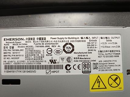
Building-in
Network Power
MODEL: 7001606-J000
FRU P/N: 7001606-J000
IBM P/N: 94Y8117
IBM FRU P/N: 94Y8118
EC NO.: N3202F
INPUT 100-240 V~ 50/60 Hz
OUTPUT +12.0Vaux === 2.5A
TOTAL OUTPUT POWER NOT TO EXCEED 900W
Manufactured Date 2015-04-14
Manufacturer: Astec International Limited
CE TUV SUD
80 PLUS PLATINUM
11 S94Y8117YK138154E0VD
in
„Pin Belegung“
·
Analoge Elektronik und Schaltungstechnik
·
10.04.2026 14:18
·
Fotos
120kHz 0.22µF 300µF 2 13 300pF 36kΩ 3 ICL8052A 12 0V 8068A 4 11 300kΩ 5 10 100kΩ -15V 6 9 5kΩ 7 8 +15V 10kΩ 10µF ANALOG GND FIGURE 11 . 4 / D2GIT LCD DPM WITH DIGIT BLANKING ON OVERRANGE 16 ICL8052A/ICL71C03, ICL8068A/ICL71C03 +5V 16kΩ 1kΩ 56kΩ 2 + 8 7 0.22µF LM311
in
„[V] Keithley 179A TRMS Multimeter defekt“
·
Markt
·
16.02.2026 16:26
Bild
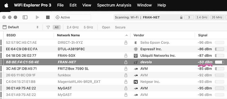
Network Name Vendor Signal
52:57:9C:A5:C1:AE DIRECT-2t-XYZ E Seiko Epson Corp. -96 dBm
EE:64:C9:DB:EC :FA DTUL-A3819F8C Espressif Inc. -86 dBm
04:18:D6:26:02:77 FRAN-5GX Ubiquiti Networks Inc. -87 dBm
B8:BE:F4:C1:56:4E FRAN-NET devolo -50 dBm
3C:A6:2F:DB:A5:71 FRITZ!Box 7590 SL AVM -85 dBm
26:65:11 :8C
in
„ESP32-C6 Mini auf externe Antenne umrüsten“
·
Mikrocontroller und Digitale Elektronik
·
07.03.2026 03:46
·
Screenshots
Bild
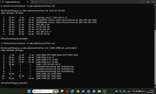
www.mikrocontroller.net [2606:4700:20::ac43:462c]
über maximal 30 Hops:
1 3 ms 6 ms 2a02:810a:595:b400:9ec 8:fcff:fe29:2ba6
2 15 ms 16 ms 2a02:810a:1:b:2
3 14 ms 10 ms 2a02:8100:6:2::8:611
4 22 ms 17 ms 23 ms 2a02:8100:6:2::8:601
5 18 ms
6 *
7 *
8 *
9 33 ms *
10 35 ms 36 ms
11 *
Ablaufverfolgung beendet.
in
„Forum seit Neustart extram langsam?“
·
www.mikrocontroller.net
·
18.07.2026 14:19
·
Screenshots
Bild
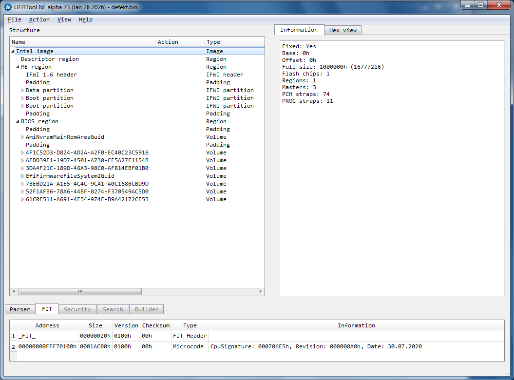
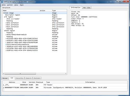
partition IFWI partition
Padding PCH straps: 74
Boot partition IFWI partition
Padding PROC straps: 11
BIOS region Padding
Padding Region
AnlyramMainRomAreaGuid Volume
Padding Padding
4F1C52D3-D824-A2F0-EC 40C2C59C19 Volume
AFD039F1-1907-4501-A730-CE5A27E1154B Padding
3DA4F21C-1B9D-46A3-98C0-CE5A27E1154B
in
„Wer kann mir ein BIOS Baustein GD25B127D programmieren“
·
Mikrocontroller und Digitale Elektronik
·
28.01.2026 09:26
·
Screenshots
DB 0xCF ;CF -- '' DB 0x32 ;32 -- '2' Address_4E8: mov r6,#0x28 Address_4EA: mov r7,#0xF9 Address_4EC : djnz r7,Address_4EC djnz r6,Address_4EA djnz r5,Address_4E8 ret DB 0x30 ;30 -- '0' DB 0xB6 ;B6 -- '' DB 0x12 ;12 -- '' DB 0x20 ;20 -- ' ' DB 0x59 ;59 -- 'Y' DB 0x11 ;11 -- '' DB 0xD2 ;D2 -- '' DB 0x59
in
„Eprom von Denon DJ Laufwerk defekt Winbond 78e52“
·
Mikrocontroller und Digitale Elektronik
·
19.12.2025 16:04
0.0689 R 0.40 0.0157 V2 0° 8° 0° 8° 1. Dimensions in inches are given for reference only DS2114 - Rev 11 page 11 /18 T1610, T1635, T1650, BTA16, BTB16 D²PAK package information Figure 15. D²PAK recommended footprint (dimensions are in mm) 1 6 .9 0 1 0 .3 0 5 .0 8 1 .3 0 3 .7 0 8 .9 0 DS2114 - Rev 11 page
in
„[V] BTA16-600 16A 600V TRIAC“
·
Markt
·
09.09.2026 20:47
----"----- ~~=:j:::::=:J:;!t:j~JFUX1 ---"- ---"-- ~~=:j:::::=:li~~tj~JR3X2 - " - _ _ _ _ _ _ _ _ j7EC 1 [3E C N J 3ECF 1 : NON-INSTAPORT ~1_8_~L""_1ll0~_100K_j BLOCKBUSTER 1 INSTAPORT 1 9287B 14X 100K 1 100K I SUNDANCE L _ _ _ _ _ _ _ L _ _ L _ _ ~ - - - ~ <OK 1 -43ECU-4 5 SPB SSB TV550 3104 313 6538 2K11 4DDR EU SO 19050_050_110503.eps 110503 2012-Nov-05 d ~
in
„Philips TV Ports ausgefallen“
·
Mikrocontroller und Digitale Elektronik
·
20.11.2025 17:40
Bild
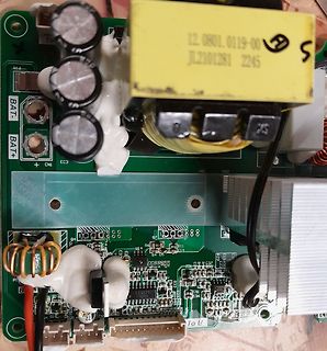
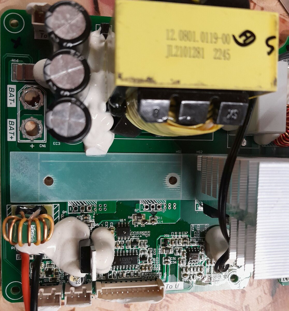
To BAT- BAT+ EC 3 CN1 HS1 HS2 12.0801.0119-00 JL2101281 2245 U14 R6 R11 R4 DS C14 R22 R23 R25 R26 R27 R28 R29 R30 R31 R32 R33 R34 R35 R36 R37 R38 R39 R40 R41 R42 R43 R44 R45 R46 R47 R48 R49 R50 R51 R52 R53 R54 R55 R56
in
„PDP8974 Ersatz gesucht“
·
Analoge Elektronik und Schaltungstechnik
·
19.04.2026 15:22
·
Platinenfotos
22.92 32.64 47.23 - 3.54 1.11 40 19.26 27.42 39.68 - 3.43 1.63 45 16.26 23.16 33.50 - 3.34 2.14 50 13.79 19.65 28.42 - 3.24 2.63 55 11 .76 16.74 24.23 - 3.15 3.11 60 10.06 14.33 20.74 - 3.07 3.57 65 8.652 12.32 17.83 - 2.98 4.02 70
in
„Gaggenau Backofen NTC-Luftfühler defekt“
·
Haus & Smart Home
·
15.01.2026 06:22
22.92 32.64 47.23 - 3.54 1.11 40 19.26 27.42 39.68 - 3.43 1.63 45 16.26 23.16 33.50 - 3.34 2.14 50 13.79 19.65 28.42 - 3.24 2.63 55 11 .76 16.74 24.23 - 3.15 3.11 60 10.06 14.33 20.74 - 3.07 3.57 65 8.652 12.32 17.83 - 2.98 4.02 70
in
„Defekt bei Sentiotec Sauna/Infrarotkabinen-Steuerung“
·
Haus & Smart Home
·
02.02.2026 15:32
Manuele programmatie.................................................................................11 Tijdelijk parameters wijzigen.........................................................................11 Gegevens opslaan..............................................................................
in
„[V] Hochspannungs-Netzteil CONSORT EV202“
·
Markt
·
14.09.2026 11:18
~lL 1I R3 11 700 11 FZHZ!,I rc s ~~~ 71FZH21,1 IOD I, 6 I. ~Qf ulf 18 8 69l.~ 614l~ t R25 11 .l5)1F c 47072 .D _ ~lf TlJ 9 ~ ~ 4 ZIRI3 7 ~ Tll I R5 _V I 8 -./:'".l R6 F ~ 67 ~[4: +1)1F 330,1.2k ,"-' 3JO.lZh . -~ '
in
„Polwechselnden Impuls mit Transistoren verstärken“
·
Analoge Elektronik und Schaltungstechnik
·
07.08.2026 02:22
, // 78 = 0x4e <N> 0x0E,0x11 ,0x11 ,0x11 ,0x11 ,0x11 ,0x0E,0x00, // 79 = 0x4f <O> 0x0F,0x11 ,0x11 ,0x0F,0x01,0x01,0x01,0x00, // 80 = 0x50 <P> 0x0E,0x11 ,0x11 ,0x11 ,0x15,0x09,0x16,0x00, // 81 = 0x51 <Q> 0x0F,0x11 ,0x11 ,0x0F,0x05,0x09,0x11 ,0x00
in
„Lib für Arduino Giga machen“
·
Mikrocontroller und Digitale Elektronik
·
23.03.2026 18:07
verdrive margin of MPX input signal THD = 1% 3 − − dB Vo(rms) AF mono output signal at pins 10 and 11 without pilot − 900 − mV (RMS value) Vo overdrive margin of output signal THD = 1% 3 − − dB V10-11 o difference of output voltage levels − − 1 dB Vo 10,11 DC output voltage (pins 10 and 11 ) 3.3 3.8 4.3
in
„TDA 7313 input AM / FM“
·
Analoge Elektronik und Schaltungstechnik
·
06.12.2025 01:25
micro-ondes 3. Minuterie à zéro L : SS 1 UU8 F F F N I N N L E OO I R RT A T 0 E EE W R O C A NG . EC Q R O AA L / VE M 6 A O O F MM IS M V OPTRCF1 C N N ** H 2 UU55 0 5 O H U 2 A 0 FFF 11 1 W / C T D Y Y T ~ . 7 M R O R R V / 0 C N F 0 5 K . N 2 / 1 8 0 P N / 6 T B - * G I 5 O A E C L R B N NS Y O E
in
„Fragen zu einem Trafo einer Sharp R733(W) Mikrowelle“
·
Analoge Elektronik und Schaltungstechnik
·
02.07.2026 09:08

 Bild
 Bild
 Bild
 Bild
 Bild

 Bild
 Bild
 Bild
 Bild
 Bild
 Bild