-
PDF
LM317.PDF
ON Semiconductor▯ LM317 1.5 A Adjustable Output, Positive Voltage Regulator THREE–TERMINAL The LM317 is an adjustable 3–terminal positive voltage regulator capable of supplying in excess of 1.5 A over an output voltage range
in „Spannungsregler für Kleinverbraucher bei 1,2V gesucht“ · Analoge Elektronik und Schaltungstechnik ·
-
PDF
Praezisions-Spannungsregler__reichelt_elektronik.pdf
30.06.26, 21:09 TEXAS INSTRUMENTS Präzisions-Spannungsregler, einstellbar, 2 ... 37 V, 150 mA, DIL | Lineare Spannungsregler günstig kau… Präzisions-Spannungsregler, einstellbar, 2 ... 37 V, 150 mA, DIL Artikel-Nr.: µA 723 DIL Hst.-Teile-Nr.: LM723 0, €5 inkl. 19% gesetzl. MwSt. zzgl. Versandkosten
in „Labornetzteil EA-3045 (0–30 V / 0–3 A) defekt - Schaltplan?“ · Analoge Elektronik und Schaltungstechnik ·
-
PDF
LM317_Datenblatt.pdf
- 25 to 150 TOP Operating junction temperature for: LM317 0 to 125 °C LM317B -40 to 125 PD Power dissipation Internally limited TSTG Storage temperature - 65 to 150 °C Note: Absolute maximum ratings are those values
in „12V Membranpumpe (KNF) läuft nur mit halber Leistung bei interner 3V-Steuerspannung (LM317)“ · Analoge Elektronik und Schaltungstechnik ·
-
Bild
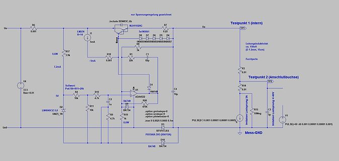
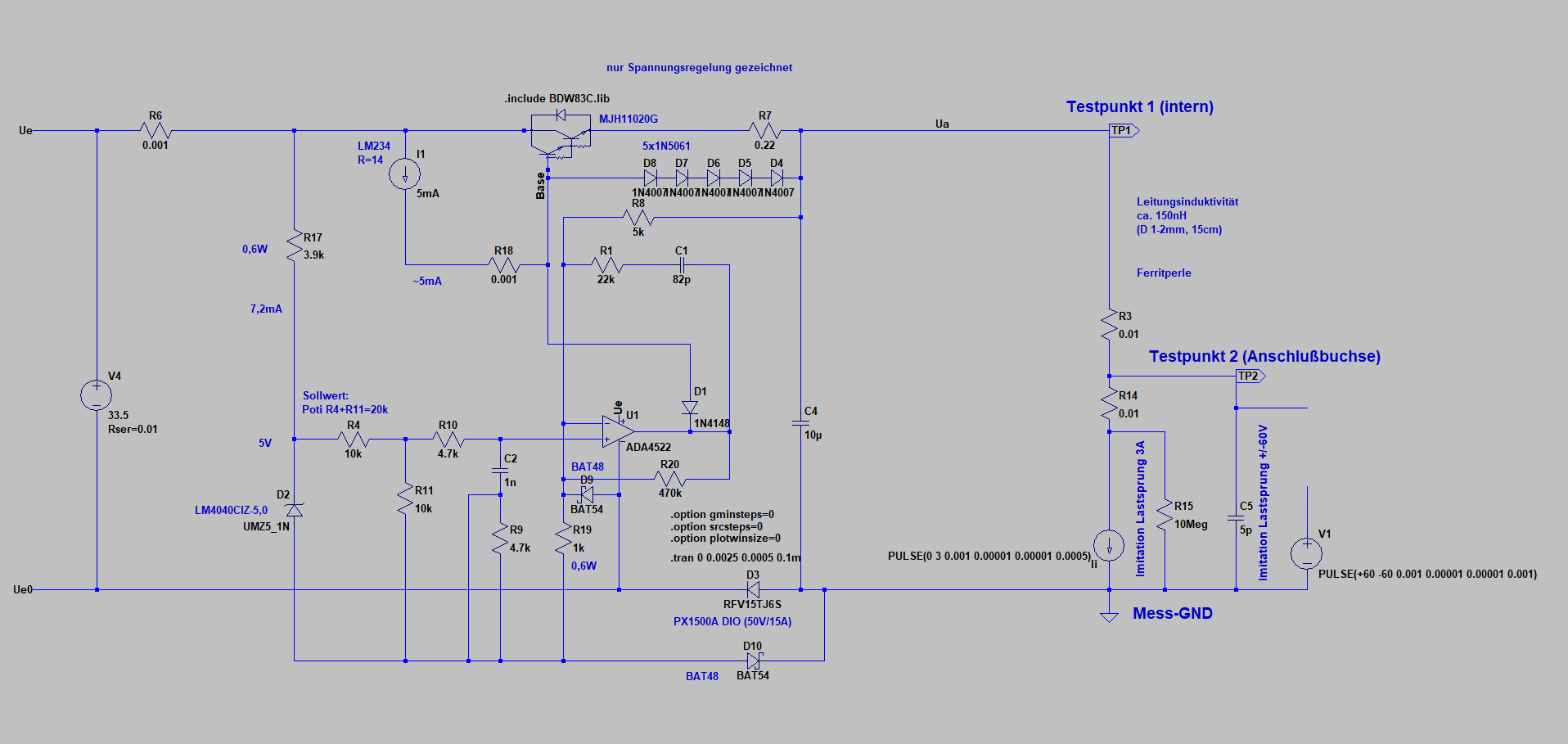
Schaltplan einer Spannungsregelung
nur Spannungsregelung gezeichnet, include BDW3C.lib, Testpunkt 1 (intern), Ue, R6, 0.01, LM234, R14, I1, 5mA, Base, 5x1N5061, R7, 0.2, Ua, TP1, Leitungsinduktivität ca. 150mH (D 1-2mm, 15cm), R17, 0,6W, 3.9k, R10, -5mA, D7, D6, D5, D4, 1N40x, N40x, N40x, N40x, N407, R8, 5k, Ferritperle, R3,
in „Nebenprojekt: Analoges Labornetzteil inkl. Schaltplan und Messungen“ · Projekte & Code · · Schaltpläne
-
PDF
Bauteile.pdf
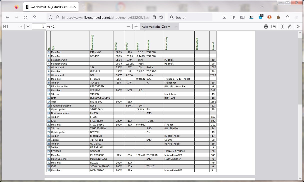
5R140P 550 V 23,0A 0,140Ω TPO220 33 Bauteil Mos-Fet IRF3315 150V 27 0,07Ω TO252-3 30 34 Bauteil Mos-Fet IRF3379 30V 0,045Ω SO8 Treiber1x N/1x PKanal 35 Bauteil Mos-Fet W5NB90 900V 9,7S 1Ω 282 36 Bauteil Mos-Fet STW13NB60 600V 13A 0,54mΩ NKanal 112 37 Bauteil Mos-Fet
-
Bild
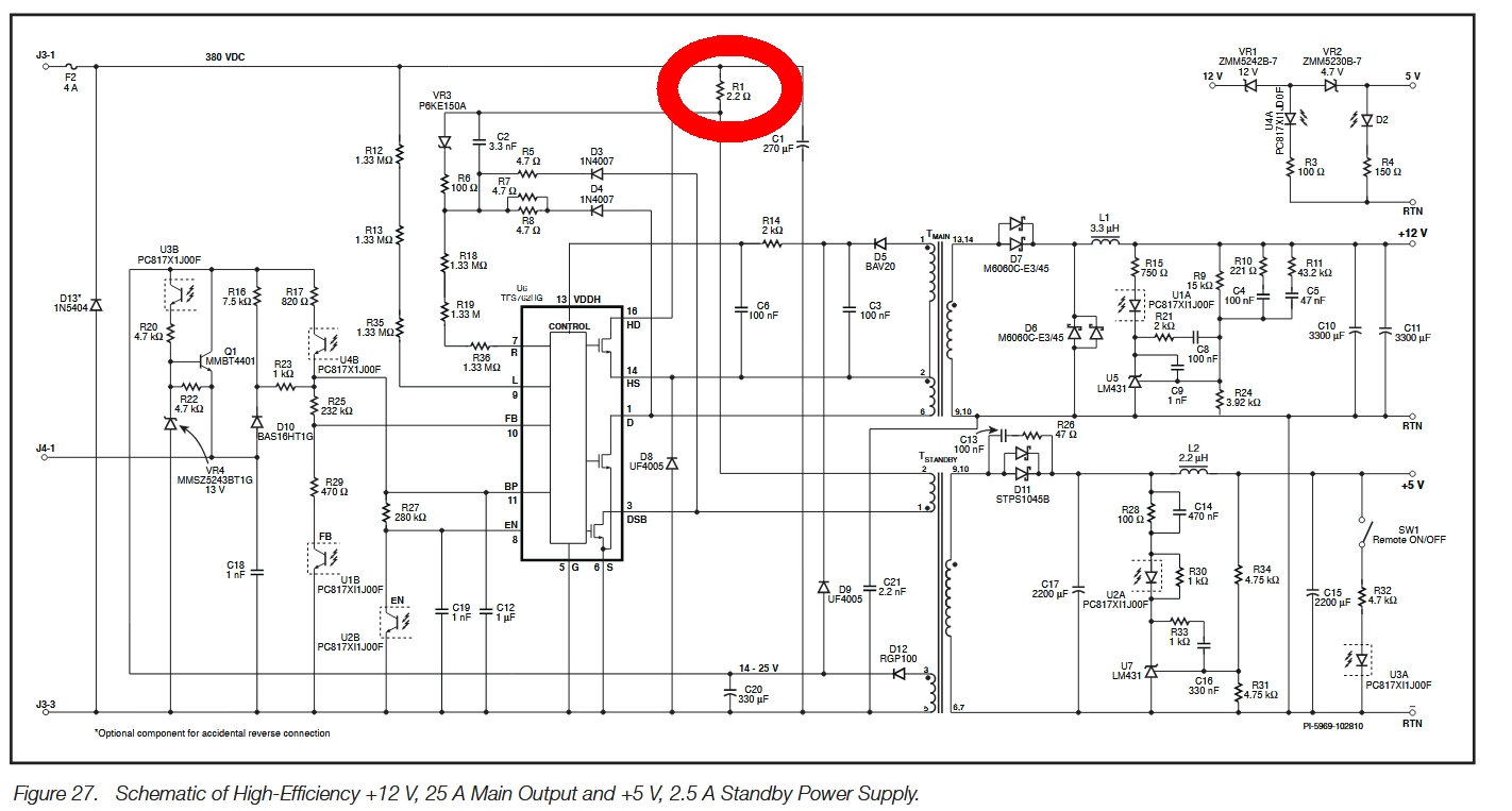
Schaltplan eines Netzteils
J3-1 F2 4A 380 VDC R1 2.2 Ω C1 270 µF VR3 P6KE150A D3 1N4007 D4 1N4007 R5 4.7 Ω R6 100 Ω R12 1.33 MΩ R13 1.33 MΩ R17 7.5 kΩ R18 1.33 MΩ R19 1.33 MΩ U18 PC81X1J00F R21 1 kΩ R23 1.33 MΩ R22 4.7 kΩ D10 BAS16HT1G U14B PC81X1J00F R25 232 kΩ R27 260 kΩ C15
in „Netzteil Lenovo 92z ThinkCentre Type 3396 defekt“ · Analoge Elektronik und Schaltungstechnik · · Schaltpläne
-
Bild
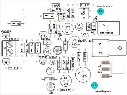
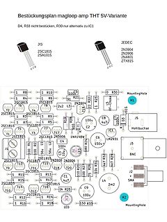
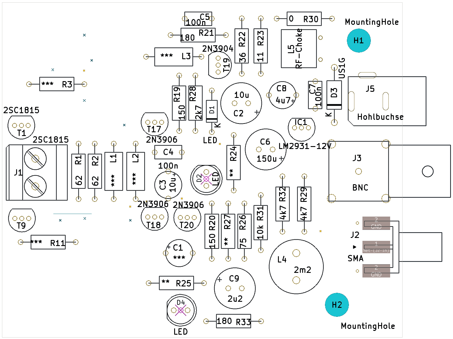
Bestückungsdruck einer Leiterplatte
C5 100n R21 180 L3 2N3904 R30 0 L5 RF-Choke T19 36 R22 23 2SC1815 R3 *** R19 150 R28 2k7 D1 01 C2 10u C8 4u7 C7 100n D3 J5 Hohlbuchse IC1 K LM2931-12V T17 2N3906 C4 100n C6 150u J3 BNC L2 L1 R1 62 62 T20 2N3906 T18 2N3906 R24 D2 LED R27 75 R20 150 R31 10k R32 4k7 R29 4k7 T9 R11
in „Kleine aktive Magnetloop-Breitbandantenne“ · HF, Funk und Felder · · Layouts
-
Bild
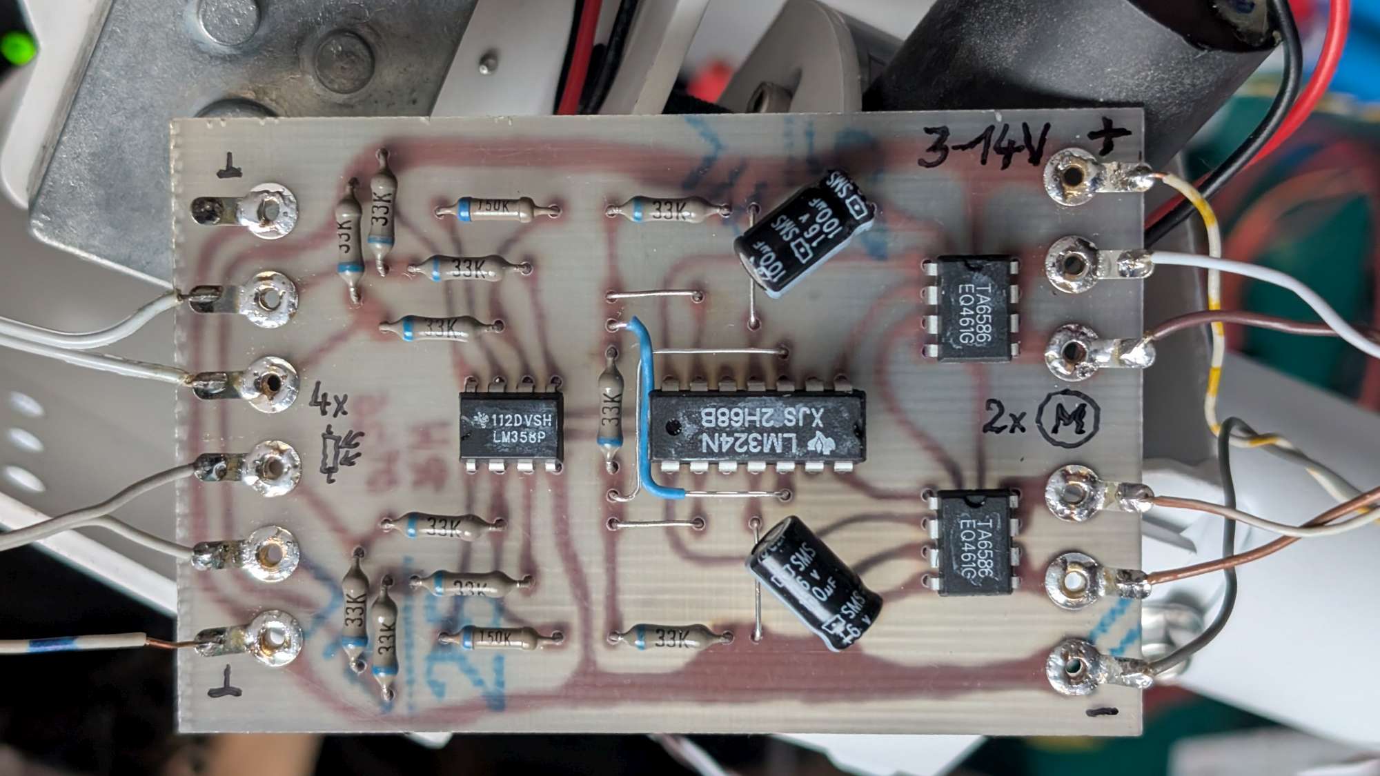
Selbstgebaute Leiterplatte mit Operationsverstärkern und Elektrolytkondensatoren
3-14V, 33K, 150K, 100uF, SMS, LM324N, XJ52H68B, LM358P, 2x M, 4x
in „einfacher analoger Sonnenfolger für 3-14V, max.5A“ · Analoge Elektronik und Schaltungstechnik · · Platinenfotos
-
Bild
Etiketten eines LM5009MM Buck-Regulators
Stock No:655-4250 Qty: 5 150mA 100V Buck Sw. Regulator LM5009MM MPN: LM5009MM/NOPB Made In Malaysia RoHS 0047266639 0170854779 RS
in „V: DIY BMS V4.4“ · Markt · · Fotos
-
Bild
Schaltplan mit LM393 Komparator und Mikrocontroller-Anschluss
VCC R6 100k VR1 100k A0 R1 10K U1.1 LM393 R3 150 2 L2 R5 1k 1k D0 P1 1 2 3 4 A0 D0 G L1 R4 10K U1.2 LM393 5 6 7 R2 100k Q1 S G
in „Feinfühlige Geräuscherkennung mit Arduino?“ · Mikrocontroller und Digitale Elektronik · · Schaltpläne
-
PDF
BU407.pdf
otherwise noted Symbol Parameter Value Units VCBO Collector-Base Voltage 330 V V Collector-Emitter Voltage 150 V CEO VEBO Emitter-Base Voltage 6 V I Collector Current (DC) 7 A C ICP Collector Current (Pulse) 10 A I Base Current 4 A B PC Collector DissipatioC (T =25°C) 60 W T Junction Temperature 150 °C J TSTG
in „Leuchtstoffröhren Vorschaltgerät 24V Reparatur-Tipp gesucht“ · Fahrzeugelektronik ·
-
Bild
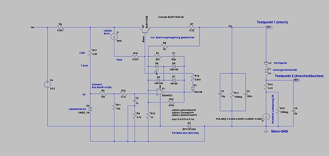
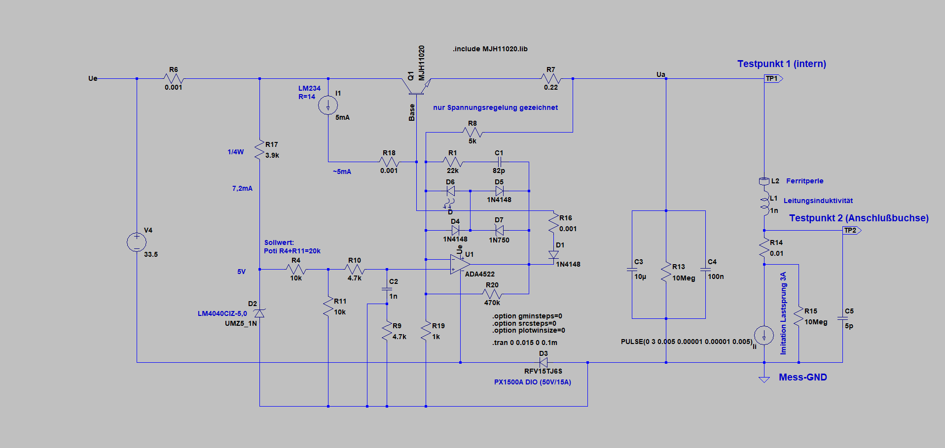
Schaltplan einer Spannungsregelung
Ue R6 0.01 LM234 R=14 I1 5mA Q1 MJH1020 Base nur Spannungsregelung gezeichnet R8 5k Ua Testpunkt 1 (intern) TP1 L2 Ferritperle L1 Leistungsinduktivitat 1n Testpunkt 2 (Anschlussbuchse) TP2 R14 0.01 R16 0.01 D1 1N4148 C3 10µ C4 10n R13 10Meg C5 5p R15 10Meg D3 RFV15TJ65 PX150A DIOD (50V/15A) Mess-GND R19 1k R1 10k R10 4.7k R4 10k Sollwert: Poti R4+R11=20k D2 LM404CIZ-5.0 UMZ_1N V4 3.5 5V C2 1n D4 1N4148 D5 1N750 D6 1N4148 U1 ADA452 R20 470k R9 4.7k .include MJH1020.lib .
in „Nebenprojekt: Analoges Labornetzteil inkl. Schaltplan und Messungen“ · Projekte & Code · · Schaltpläne
-
Bild
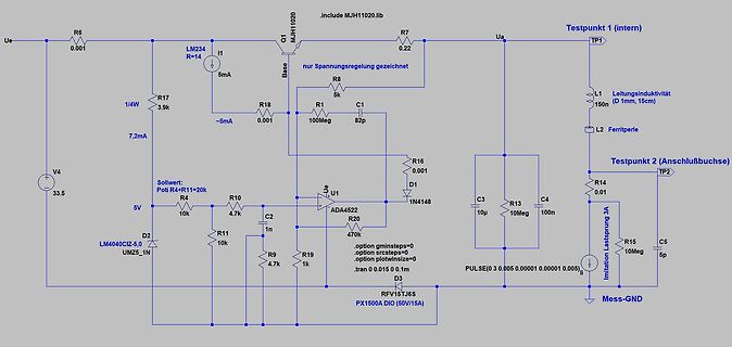
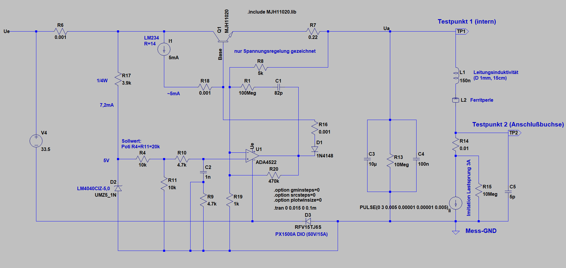
Schaltplan einer Simulation einer Spannungsregelung
Ue R6 0.01 LM234 R=14 I1 5mA Q1 MJH1020 Base nur Spannungsregelung gezeichnet R8 5k R17 3.9k R1 0.01 C1 82p Ua Testpunkt 1 (intern) TP1 L1 Leitungsinduktivität 150n (D 1mm, 15cm) R18 ~5mA 7,2mA V4 3.5 Sollwert: Poti R4+R1=20k R4 10k R10 4.7k R1 10k C2 1n D2 LM404CIZ-5.0 U1 ADA452 R20 470 .option gminsteps=0 .option srcsteps=0 .option plotwinsize=0 .option Imitation PULSE(0 3 0.005 0.01 0.01 0.05) .tran 0 0.015 0 0.1 D3 RFV15J6S R16 0.01 D1 1N4148 C3 10u R13
in „Nebenprojekt: Analoges Labornetzteil inkl. Schaltplan und Messungen“ · Projekte & Code · · Schaltpläne
-
Bild
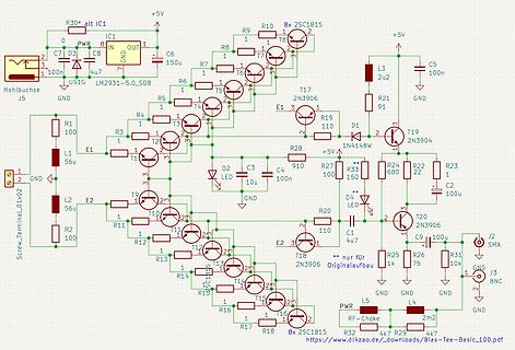
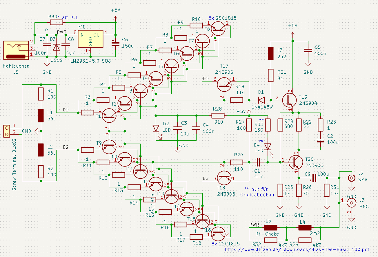
Schaltplan einer Bias-T Schaltung
R30* alt IC1, +5V, C7 100n, C6 150u, C8 4u7, GND, US1G LM2931-5.0_S08, R1 100, L1 56u, L2 56u, R2 100, J5 Hohlbuchse, T1 bis T18, T19 2N3904, T17 2N3906, 8x 2SC1815, D1 1N4148W, D2 LED, D4 LED, C3 10u, C4 100n, C5 100n, C9 100u, C1 4u7
in „Kleine aktive Magnetloop-Breitbandantenne“ · HF, Funk und Felder · · Schaltpläne
-
PDF
Bauteile.pdf
Feinsicherung 250V 0,315A Träge PE10St. 20 5 Widerstand 22K 350V 2W 5% Radial 1000 6 Mos-Fet IRF3315 150V 27 0,07Ω TO252-3 30 7 Widerstand 30K 150V 0,25W Radial 2000 8 Mos-Fet IRF3379 30V 0,045Ω SO8 Treiber1xN/1xPKanal 9 Treiber TLP250 35V 1,5A IC Treiber#al 85 10 Microkontroller P80C592FFA 8BitMicrokontoller
in „Elektronik Bauteile Neuwertig , meist Leistungselektronik“ · Markt ·
-
Bild
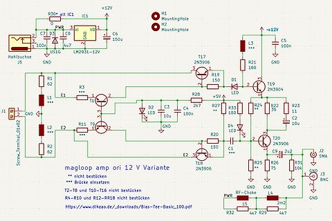
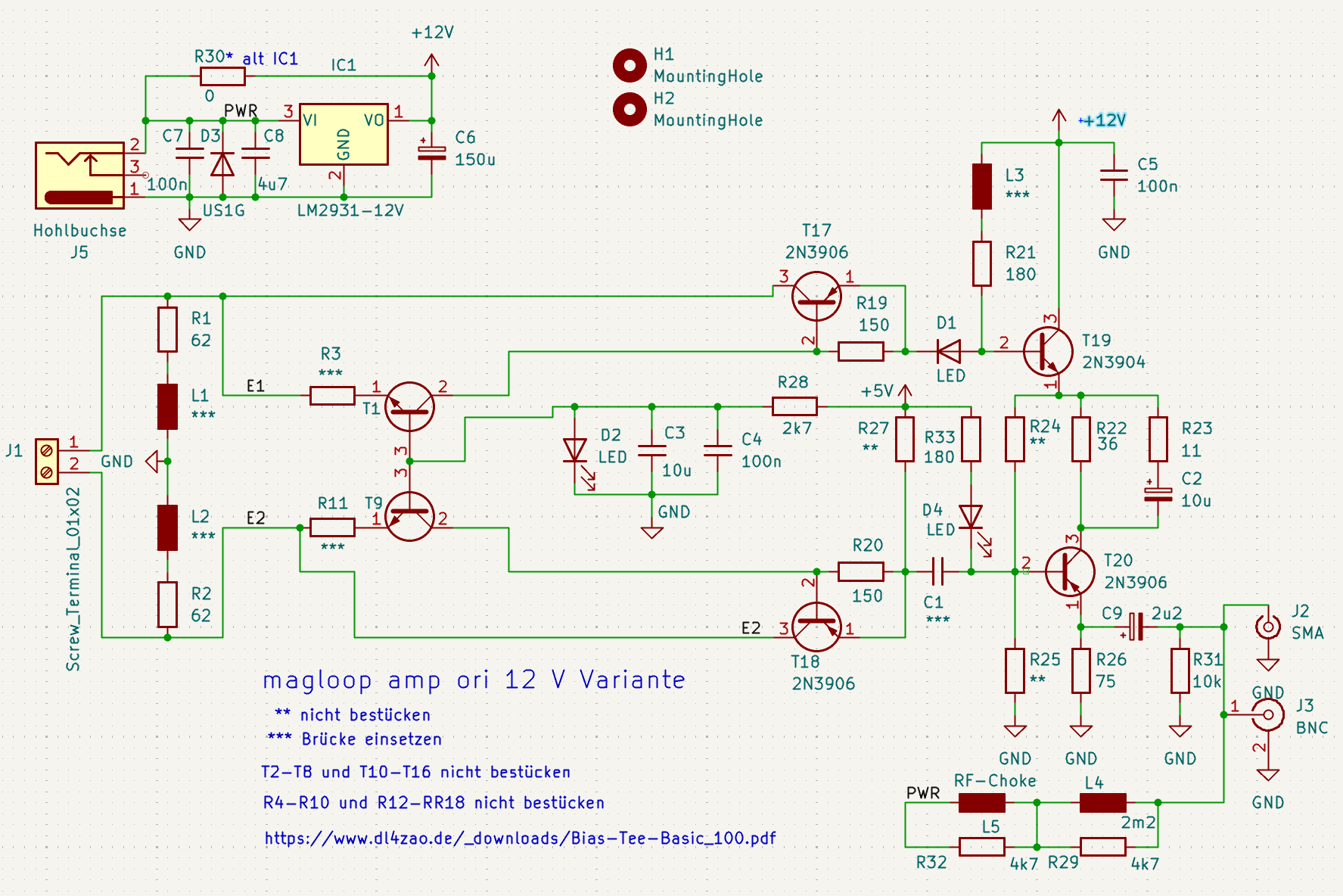
Schaltplan eines Magloop-Verstärkers
R30* alt IC1 IC1 +12V 0 PWR 3 VI V0 C6 100n 1u7 GND C7 D3 C8 US1G LM2931-12V H1 MountingHole H2 MountingHole J5 GND R1 62 L1 *** E1 J1 2 GND L2 *** E2 T1 R3 *** 2 R11 T9 1 2 D2 LED C3 10u C4 100n R28 2k7 R33 180 R24 ** R23 11 T17 2N3906 R19 150 D1 2 T19 2N3904 R22 36 C2 10u R20 150 D4 LED C1 *** T20 2N3906 J2 SMA R25 75 R26 GND J3 BNC R31 10k GND GND R32 L5 4k7 R29 2m2 4k7 RF-Choke magloop amp ori 12 V Variante ** nicht bestücken *** Brücke einsetzen T2-T8 und T10-T16 nicht bestücken
in „Kleine aktive Magnetloop-Breitbandantenne“ · HF, Funk und Felder · · Schaltpläne
-
PDF
A_simple_state-of-the-art_spectrometer_for_student.pdf
of the grating of 58l rad: Da ¼ Dk 5:8 10 5 rad. Consequently, 3.45lm. 10 full rotations (Dk ¼ 1000) correspond to Da ¼ 3:3 . In reality, the imaging resolution is limited by aberra- tions4 and we find experimentally FWHM exp 13 lm (see Within this range, we can approximate
in „Physikprojekte“ · Offtopic ·
-
Bild
Tabelle mit elektronischen Bauteilen und Spezifikationen
Feinspeicher 250V 4,0A Fink PE 10 St. Widerstand 22k 250V 0,315A Radial 1000 Widerstand IRF 3315 150V 27 $\Omega$ 0,07 $\Omega$ TO-223 30 Widerstand 30k 150V 0,29W 0,045 $\Omega$ SOT 2000 Mos-Fet TLP 250 35V 1,5A IC #al 8 Treiber BT136-600 RAM 600V 25A 1 $\Omega$ 1691 Optokoppler BT136-600 BT136-600
in „Elektronik Bauteile Neuwertig , meist Leistungselektronik“ · Markt · · Screenshots
-
Bild
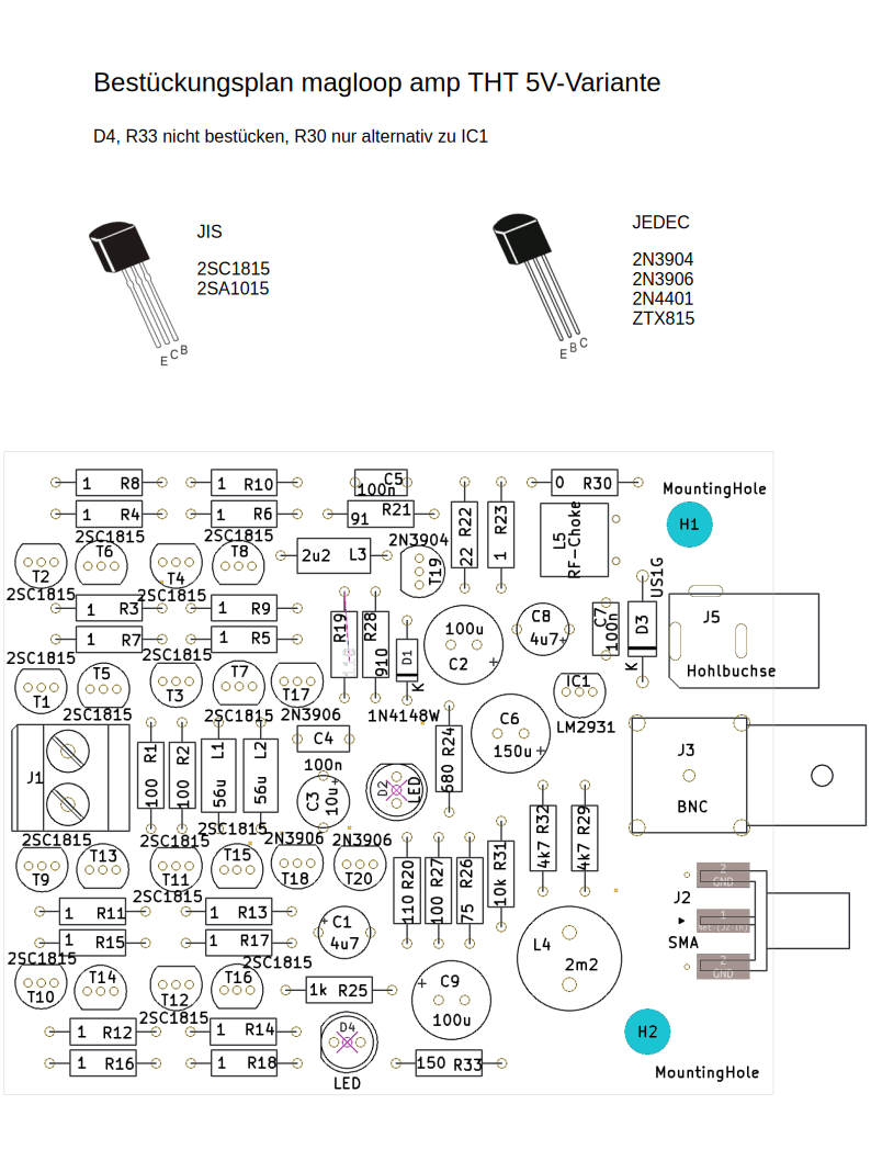
Bestückungsplan magloop amp THT 5V-Variante
C5 100n, R21 91, R30, R22, R23, L3 2u2, T19, CB, C4 100u, C7 100n, D3, J5, USIG, Hohlbuchse, IC1, LM2931, R4, R6, T6, T8, 2SC1815, T4, 2SC1815, R1, R9, R7, R5, 2SC1815, T5, T7, 2SC1815, 2N3906, N14148W, C6 150u, R19, 910, D1, J1, R100, R102, 56u, 56u, L2, C2, R47, R29, 4k7, 2SC1815, T3, T13, T11, 2SC1815
in „Kleine aktive Magnetloop-Breitbandantenne“ · HF, Funk und Felder · · Layouts
-
PDF
Schematic_Netzteil-TL071-v.2_2026-10-22.pdf
4.7k R8 1.5k C22 BZX55C3V3 R9 C3 B 2 2.2k 220p B Set C4 f SW1 e 3 R11 47p R r R10 Umax V o 10k 2 R12 150k 4.7n + U2 D4 1 3 S 3 1k TL071CP C5 1 U1 1 U3 1 D6 C6 2 TL431 1 +12V 5 +12V 100n 5 7 7 47u MBR10100F R27 R13 R14 2 4.7k 10k 8.2k 2 R15 6 R16 D7 D8 6 6.6k 3 4.7k 3 Q6 8 4 GND 8 4 4 C21 R26 D11 2 -12V
in „Nebenprojekt: Analoges Labornetzteil inkl. Schaltplan und Messungen“ · Projekte & Code ·
-
PDF
Schematic_Netzteil-TL071-v.2_2026-10-29.pdf
R8 1.5k C22 3.3V R9 C3 B 2 2.2k 100p B Set C4 R7 SW1 e 3 R11 47p 470 R28 r R10 Umax 10k o 10k 2 R12 150k 4.7n U2 D4 1 3 S 3 1k e TL071CP C5 1 U1 1 U3 R 1 D6 C6 2 TL431 1 +12V 5 5 +12V 100n 5 7 Q11 + 7 Low ESR R27 R13 R14 IRF9530 2 4.7k 10k 8.2k 2 6 R16 D7 D8 6 3 4.7k 3 Q6 R15 8 8 4 R7* 6.6k 4 C21 R26
in „Nebenprojekt: Analoges Labornetzteil inkl. Schaltplan und Messungen“ · Projekte & Code ·
-
PDF
T-3.pdf
) 416-3113-007 1 Q105 TRANSISTOR(DTA124TS/2SA1589/DTA124TSATP,TAPING)416-KE200S-024 1 IC109 IC(LM78L05 TAPING TO-92) 417-PMSE1-161 1 D.D. MOTOR(198*150mm 94V0) 405-STR880-670B 1 R102,R112 CARBON FILM RESISTOR(150K OHM,1/6W,J,T-26) 412-3113-046 2 R131 CARBON FILM RESISTOR(2.2K OHM,1/6W,J,T-26) 412
in „Eprom von Denon DJ Laufwerk defekt Winbond 78e52“ · Mikrocontroller und Digitale Elektronik ·
-
Bild
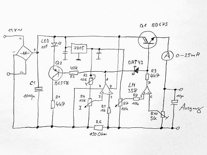
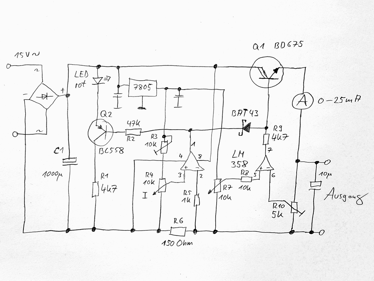
Handgezeichneter Schaltplan einer Konstantstromquelle
15V ~ LED rot 7805 Q2 BC558 47k R3 10k R2 R4 10k 4 LM 358 R5 1k R7 10k R8 3 6 R9 4k7 R10 5k 10µ C1 1000µ Q1 BD675 A 0-25mA BAT 43 R6 150 Ohm Ausgang
in „Strom-/Spannungsquelle regelbar 1,5V, 3V, 9V (+-0,5V), 0..20mA“ · Analoge Elektronik und Schaltungstechnik · · Schaltpläne
-
PDF
100807728a.pdf
® Product Manual Standard models ST2000LM015 ST1000LM048 ST500LM030 100807728, Rev. A September 2016 Document Revision History Revision Date Pages affectedand Description ofchange Rev. A 09/06/2016 Initial release a © 2016SeagateTechnologyLLC.Allrightsreserved
in „Komponenten für Low Power Fileserver?“ · PC Hard- und Software ·
-
Bild
Schaltplan einer isolierten Spannungsregelung
Unregulated_Voltage Q7 R29 ISO_GND Gate ISO-12V OUT U16 LM675T/NOPB +IN -IN VCC -VEE R30 10K ISO_GND GateDriver R17 100K C48 1n Q3 ISO+5V/E-N 8 7 6 5 4 3 2 1 NC NC HCNR200-300E ISO_GND ISO_GND R21 150R +5V C46 1n Q6 MMBT3906 GND GND U14 MCP6021-E/SN 8 7 6 5
in „Regelstrecke isoliert & analog“ · Analoge Elektronik und Schaltungstechnik · · Schaltpläne
-
Bild
Schaltplan mit Gate-Treiber, Optokoppler und Operationsverstärkern
Unregulated Voltage, Q7, 1, 2, 3, Gate, R29, 0R0, U16, +IN, -IN, OUT, ISO+12V, -VEE, VCC, ISO-12V, LM675T/NOPB, R30, 10K, R32, 10K, ISO_GND, DAC U SOLL, Regulated Voltage, R22, 30K, R23, 10K, R24, 16K, R26, 0R0, R27, 1K0, R28, 10K, C66, 10n, C64, 220p, C65, 10n, MCP6021-E/SN, GND, +5V, R17, 100K, C48
in „Regelstrecke isoliert & analog“ · Analoge Elektronik und Schaltungstechnik · · Schaltpläne
-
PDF
fsp_technology_fsp202-4fs01_runtkb074wjqz_psu.pdf
1 2 3 4 5 6 7 8 I HOT CHASSIS COLD CHASSIS " " " " SCK15046 SF46G 47uF,200V 47uF,200V SC101 F101 8LM0265901 8LM0289201 TH101 P 8LM0289201 8TI0120601GP MUR460 BEAD + FB101 T101:12 D901 C901 C902 70V/1.8A LF103:1 LF101:2 L603:1 L601:1 L601:3 D601 FB601 B JUMP V-LED SC101:3 L 4 SF46G T4AH/250V " 4 + +
in „Welche Diode ist das?“ · Analoge Elektronik und Schaltungstechnik ·
-
PDF
Elektor_1978-06.pdf
regulators. Pulse Generator. All pulse 999 ms, pulse width isfrom 3 ns video games using hexadecimal The LM 137/LM 237/LM 337 are parameters are programmable to 999 ms both with three digits - width, period, delay, transition of resolution. code. Extremely compact CHIP-8 adjustable 3-terminal negative times
-
PDF
Stenorette_2010_SW.pdf
behindern. ! Pa rallelstellung Fallgeschwindigl<eit Abb.4 Kopl iustieren BandqeschuindiqkeiL einstellen 150 Hz-Aufzeichnung der Justiercassette 796 ab- spi,efen, Die Eandgeschuindigkeit uird auf 2r38 cm/sec über fvleßbandeingestellt. lv]it R 17 er- Sollgbeschuj.ndigkeitung in der Platine) uird die eingestell
in „Recht auf Reparatur“ · Offtopic ·
-
PDF
ADC0803_4.pdf
40 to +85 ⋅C ADC0803/04-1 CD 0 to +70 ⋅C ADC0803/04-1 CN 0 to +70 ⋅C T Storage temperature -65 to +150 ⋅C STG TSOLD Lead soldering temperature (10 seconds) 300 ⋅C P Maximum power dissipation D TA=25⋅C (still air) N package 1690 mW D package 1390 mW NOTES: 1. Derate above 25⋅C, at the following rates:
in „Verständnisfrage zum ADC080x (VIN-MIN/DC-Offset)“ · Analoge Elektronik und Schaltungstechnik ·
-
PDF
Intersil_ICL8052_ICL8068_ICL71C03.pdf
should be made adjustable as an offset trim. 12 ICL8052A/ICL71C03, ICL8068A/ICL71C03 +5V 5 4 3 2 1 150Ω 150Ω 7447 a b 4.7kΩ c B1 150Ω d B2 e B3 f B4 g RBI ICL71C03 +5V V+ 1 BUSY 28 47kΩ 2 41/ / 3 / (LSD) D 27 2 2 1 3 POLARITY D 26 2 4 RUN/HOLD D3 25 5 COMP IN D4 24 1.0µF -15V 6 V- (MSB) B823 ICL8068A
-
PDF
asus-p701-unlocked.pdf
16V _ 3 +IN1 -IN2 6 2 2 0 2 0 1 1 2N7002 4 VEE +IN2 5 H431_REF m [38] BAT_IN# 1 PC42 il PR18 G S 2 1 LM393MX 1 1UF/16V PD5 1SS355 2 1 3KOhm 2 2 B 2 2 /1 B PR68 Vacin=2.55V 150KOhmPR19 MAX8724_REF PQ9 PC48 GND 1 2 2N7002 10KOhm 1UF/16V A/D_DOCK_IN 3 3 +3VA 1 GND 97.6KOhm 2 V D 1 PR20 1 1 5 m PR22 68.1KOhm
-
PDF
Sinuswechselrichter.pdf
die Schaltung zur Erzeugung der Versorgungsspannun- gen. In der USV übernehmen Festpannungsregler (LM340 und 7805) die Erzeugung der +12V und +5V Versorgungsspannungen. Desweiteren erzeugt eine Ladungspumpe die für einige Operationverstärker notwendige negative Versorgungsspannung von -9V. Q40222 F -
in „Wechselrichter Spannung und Frequenz steuerbar für Teichpumpe“ · Haus & Smart Home ·
-
Datei
schaltplan.html
1.6933px" lengthAdjust="spacingAndGlyphs" text-anchor="middle" opacity="0" stroke-opacity="0" id="text53">LM358</text> <g class="stroked-text" id="g118"> <desc id="desc53">LM358</desc> <path d="m 121.0431,82.6793 h -0.6048" id="path54" /> <path d="m 120.4383,82.6793 v -1.27" id="path55" /> <path d="m 121.4664,82.6793
in „Benutzt hier jemand "Circuit Diagram"?“ · PC Hard- und Software ·
-
PDF
ct.17.04.150-153.pdf
virtuellerSchlüssel beliebig viele Werte – die Ein- Persönliches PDF für alle Leser der c't aus 30625 Hannover 150 c’t 2017, Heft 4 Windows-Registry | FAQ träge auf der rechten Seite im regedit. DieRegistryverteiltsichaufmehrere undbestätigenSiedieNachfrage.Scrollen JederWertbesitzteinenNamenundeinen ß sogenannte
-
PDF
Orion_Rev_3.0__1_.pdf
VCCH_GXB W7 J5 GND GND W4 VCCH_GXB GND GND J7 GND GND W5 J8 GND GND W6 K1 GND GND W9 K12 Y1 EP4CGX150F896 K14 GND GND Y10 K2 GND GND Y14 VERSION : 1.0 K20 GND GND Y16 PAGE : 1 of 10 K7 GND GND Y2 DATE : JUNE 2010 K8 GND GND Y23 GND GND Y26 GND GND Y29 GND Y9 EP4CGX150F896 VERSION : 1.0 PAGE : 10 of
in „Suche Firma die für Privat BGA FPGA reballing macht“ · Markt ·
-
PDF
PMT_handbook_v4E.pdf
described in subsequent sections. Quantity Unit Name Symbol watts [lumens] Radiant flux [Luminous flux] W [lm] Radiant energy [Quantity of light] joules [lumen sec.] J [lm·s] Irradiance [Illuminance] watts per square meter [lux] W/m [lx] Radiant emittance watts per square meter W/m [lm/m ] 2 [Luminous emittance
in „Suche nach geeignetem OpAmp als Impedanzwandler“ · Analoge Elektronik und Schaltungstechnik ·
-
PDF
ADC0801_05.pdf
voltage level specifications A converters that use a differentialpotentiometric n Works with 2.5V (LM336) voltage reference D ladder— similar to the 256R products. These converters arechip clock generator C designed to allow operation with the NSC800 and INS8080AV to 5V analog input voltage range with
in „Verständnisfrage zum ADC080x (VIN-MIN/DC-Offset)“ · Analoge Elektronik und Schaltungstechnik ·
-
PDF
REN_icl7106-07-07s_DST_20251218.pdf
. . . . . . . Maximum Junction Temperature . . . . . . . . . . . . . . . . . . . . . . . . . . . .+150°C Analog Input Voltage (Either Input) (Note 6). . . . . . . . . . . . . . . Maximum Storage Temperature Range . . . . . . . . . . . . . .-65°C to +150°C Reference Input Voltage (Either Input) . . .
in „Panel-Meter KAIFU FR-4“ · Mikrocontroller und Digitale Elektronik ·
-
PDF
TF5000CI.pdf
sinking provided, the thermal shutdown circVoltage Range takes over preventing the IC from overheating. LM7805C 5V Considerable effort was expanded to make the LM78XX se- ries of regulators easy to use and mininize the number7812C 12V LM7815C 15V Schematic and Connection Diagrams Metal Can Package TO-3 (K) Aluminum TL/H/7746–2 Bottom View Order Number LM7805CK, LM7812CK or LM7815CK See NS Package Number KC02A Plastic Package TO-220 (T) TL/H/7746–3 Top View Order Number LM7805CT, LM7812CT or LM7815CT See NS Package Number T03B TL/H/7746–1 C1995 National
in „CPU SAA7219 per Jtag auf Basis FT2232H ansprechen - Tool schreiben“ · PC Hard- und Software ·
-
PDF
pm2519ocr.pdf
_ v1605 ‘BC559B 4822 130 44358 vi1651 BZV85-C18 83213032129 v1652 BZV85-C18 5321303212 v1653 BYV27-150 4822 130 31628 vi654 BYV27-150 48213031628 V1655 BYV27-150 48213031628 v1656 BYV27-150 48213031628 vi1657 BAWe2 48213030613 v1658 BAW62 48213030613 i6610 BAW62-B3V3 48213030613 v162 BZX79-83V3. 83213031504
in „Pjilips PM2519“ · Markt ·
-
PDF
6ff78f.pdf
227,228,229,233 3 0-15-0221 RESISTOR 220O (SMD) 1 R270 3 0-15-0222 RESISTOR 2K2 (SMD) 8 R144,145,149,150,151,152,156,157 3 0-15-0242 RESISTOR 2K4 (SMD) 2 R259,264 3 0-15-0272 RESISTOR 2K7 (SMD) 3 R154,155,209 3 0-15-0273 RESISTOR 27K (SMD) 2 R340,342 3 0-15-0303 RESISTOR 30K (SMD) 10 R33,99,100,106,107,108,111,112,113,115
in „Mischpult "Alesis Multimix 8" (Knallen auf allen Ausgängen)“ · Analoge Elektronik und Schaltungstechnik ·
-
PDF
FT_1984_Heft_01_OCR.pdf
X X 319x 145x235 HITACHI DA 800 X X X X X X X X X 405x 110x 265 ITT HiFi 9015 X X X X X X X 334 x 150 x 273 LOEWE CD 900 X X X X X X X 420 x 86 x300 MARANTZ CD 73 X X X X X X X 420 x 87 x345 MITSUBISHI DP-103 X X X X X 350 x 100 x 320 NORDMENDE 2000 X X X X X X X X 320 x 145 x 235 PHILIPS CD 202 X X
in „[VS] verschenke Taststift“ · Markt ·
-
PDF
pm2534ocr.pdf
NTC R1152 becomes too high, the thyristor starts conducting and the fuse w i blow. DC amp! + 3 =AA| 150mVv 10x x The AC input current ranges are shunted in the same way as the DC currents. The voltage from the shunt is supplied to the I, input of R 1 3 0 7 .verter. Input Ij of the 0Q0068 is earthed via resistor Range Shunt sensitivity via 0Q0068 30 mA 150 mV 0,3 Vv 3 A 150mV 3 V 3 . 3 .R e s i sm e a s u r e m e n t The unknown resistance is connected between V Q a n d 0 V input sockets and supplied internally by a constant current source (figure 3.7
in „Pjilips PM2519“ · Markt ·
-
PDF
53131a_53132a_bedienungsanleitung_deutsch_komprimiert.pdf
tintervallauflosungfiir d en H 53 132A b trägt 12 Anzeiigestellen eitintervallauflösung ür p roS ekunde bz w. 150 Pikossekunden. M Hit lfede H IP-IB b tet er 1000 M sungen pn ro Sekunnde und is ieall fü de A TE--Systembetrieb ge eignet. Zu de nr undlegendenn M Bfunktionen de H 53 P 131A//132A ge hörren Freq uenz
in „[V] HP/Agilent 53131a/53132a Bedienungsanleitung deutsch“ · Markt ·
-
PDF
technical.pdf
. . 148 11.5.2 Physical model . . . . . . . . . . . . . . . . . . . . . . . . . . . . . . . . . . 150 11.5.3 Small signal model . . . . . . . . . . . . . . . . . . . . . . . . . . . . . . . . 152 11.5.4 Noise model . . . . . . . . . . . . . . . . . . . . . . . . . . . . . . . . . . . . 155 11.5.5 Temperature
-
PDF
ihv.pdf
mit booleschen Werten . . . . . . . . . . . . . . . . . . . . . . . . . . . . . . . . . . . . . . 150 6.7. Typumwandlungen (Conversions) und ihre Regeln {#Typumwandlungen}. . . . . . . . . . . . . . . 151 6.7.1. Integer-Promotion (Ganzzahlpromotion). . . . . . . . . . . . . . . . . . . . . . . . . .
in „Mein neues C-Buch braucht ehrliche Kritik“ · Softwareentwicklung ·