-
PDF
LM317_Datenblatt.pdf
22 page 20/34 LM217, LM317 D²PAK (SMD 2L STD-ST) type A package information Table 10. D²PAK (SMD 2L STD-ST) mechanical data mm Dim. Min. Typ. Max. A 4.40 4.60 A1 0.03 0.23 b 0.70 0.93 b2 1.14 1.70 c 0.45 0.60 c2 1.23
in „12V Membranpumpe (KNF) läuft nur mit halber Leistung bei interner 3V-Steuerspannung (LM317)“ · Analoge Elektronik und Schaltungstechnik ·
-
PDF
LM317.PDF
DIFFERENTIAL (Vdc) Figure 9. Temperature Stability Figure 10. Minimum Operating Current http://onsemi.com 5 LM317 100 CAdj= 10 F ) ) 120 ( 80 d N ( 100 I Without Adj I C 60 C CAdj= 10 F J J 80 R E Without Adj L 40 E 60 P P R V inV out= 5 V I 40 R IL= 500 mA , Vin 15 V R 20 f = 120 Hz R Vout= 10 V T = 25⋅C 20
in „Spannungsregler für Kleinverbraucher bei 1,2V gesucht“ · Analoge Elektronik und Schaltungstechnik ·
-
PDF
fsp_technology_fsp202-4fs01_runtkb074wjqz_psu.pdf
LC-60LE651 MK2 LC-60LE652 MK2 60” Power Unit PWB 1/2 ( RUNTKB074WJQZ) Side A I H G F E D C B A 1 2 3 4 5 6 7 8 9 10 11 12 13 14 15 16 105 LC-60LE651 MK2 LC-60LE652 MK2 60” Power Unit PWB 2/2 (RUNTKB074WJQZ
in „Welche Diode ist das?“ · Analoge Elektronik und Schaltungstechnik ·
-
PDF
100807728a.pdf
® Product Manual Standard models ST2000LM015 ST1000LM048 ST500LM030 100807728, Rev. A September 2016 Document Revision History Revision Date Pages affectedand Description ofchange Rev. A 09/06/2016 Initial release a © 2016SeagateTechnologyLLC.Allrightsreserved
in „Komponenten für Low Power Fileserver?“ · PC Hard- und Software ·
-
PDF
Bauteile.pdf
6,3mm Erregerspule24 VDC/200 mA 24 Bauteil IGBT IRG4PH30K 720V 10A TO-247 106 25 Bauteil IGBT STGW45HF60WD 600V 45A TO-247 6 26 Bauteil IGBT G4PH30K 300V 33A TO-247 Leistungstransistor 27 Bauteil IGBT IRG 4PH30K 600 10A N Kanal 28 Bauteil Komparator LM339 Bedrahtet 2 29 Bauteil Leiterplatten SteckverbindeFTMH
-
Bild
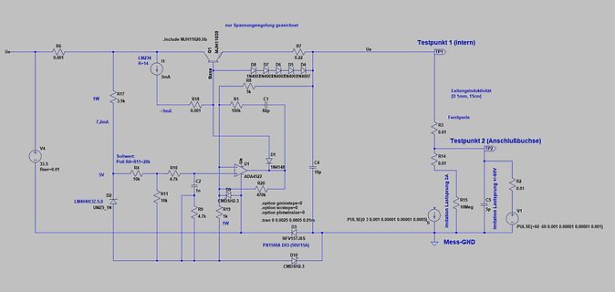
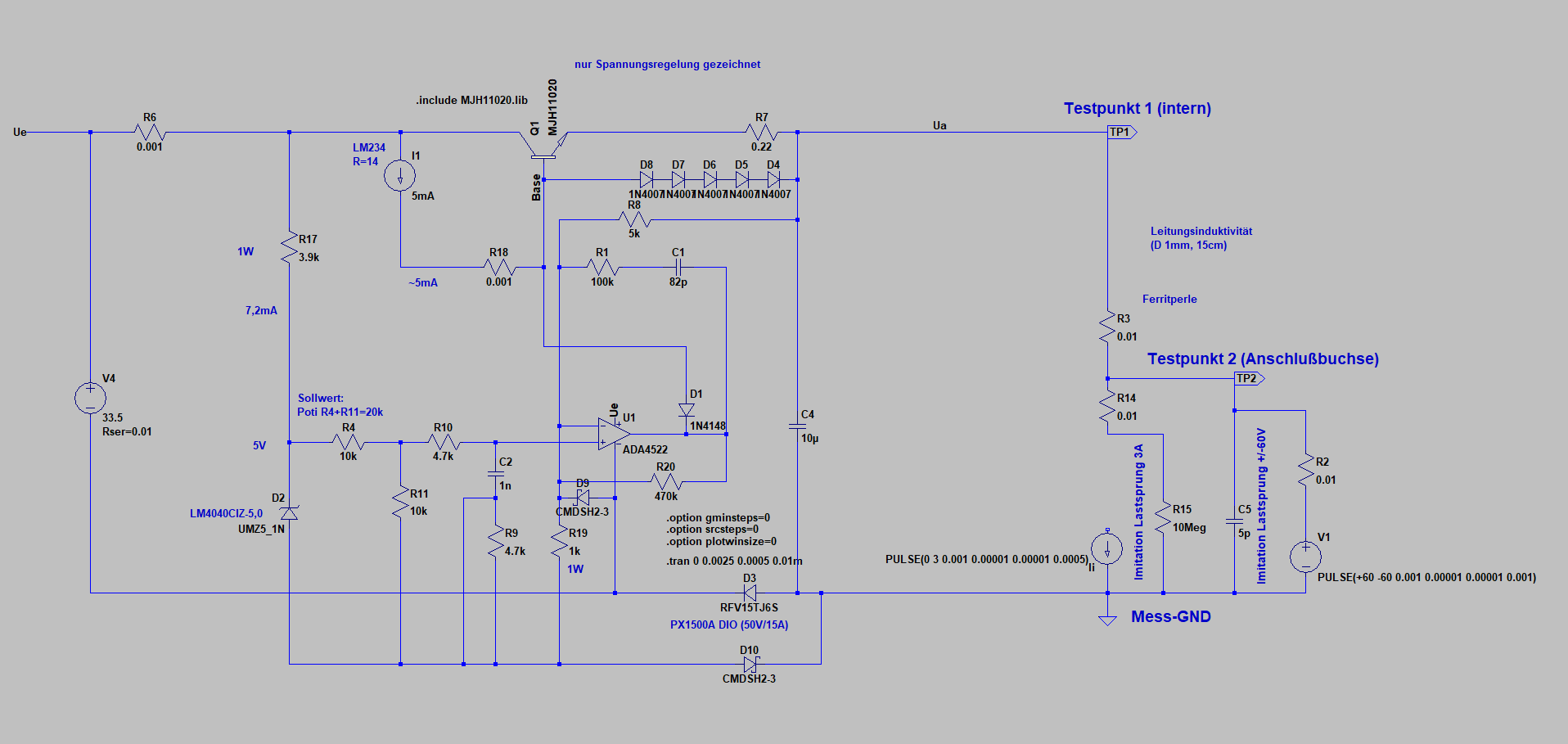
Schaltplan einer Spannungsregelung
C4 10u D2 LM4040CIZ-5.0 UM25_1N V4 33.5 Rser=0.01 5V R10 10k C2 4.7k D1 1N4148 U1 ADA4522 R20 470k R1 10k 1n R9 4.7k R19 1W D3 CMDSH2.3 D10 CMDSH2.3 Imitation Lastprung 5A Imitation Lastprung +40V R2 0.01 C5 10Meg 5p V1 PULSE(+60 -60 0.01 0.01 0.01 0.01) Mess-GND
in „Nebenprojekt: Analoges Labornetzteil inkl. Schaltplan und Messungen“ · Projekte & Code · · Schaltpläne
-
Bild
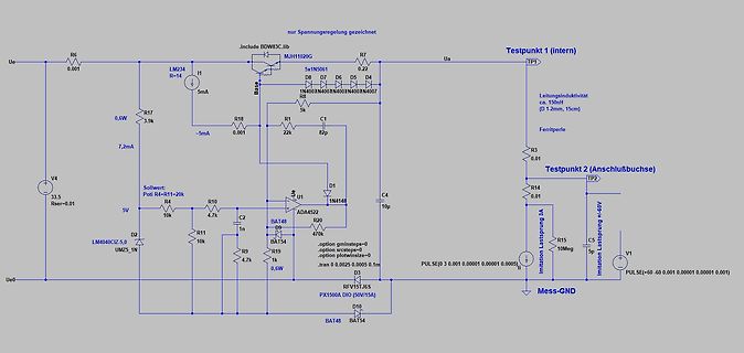
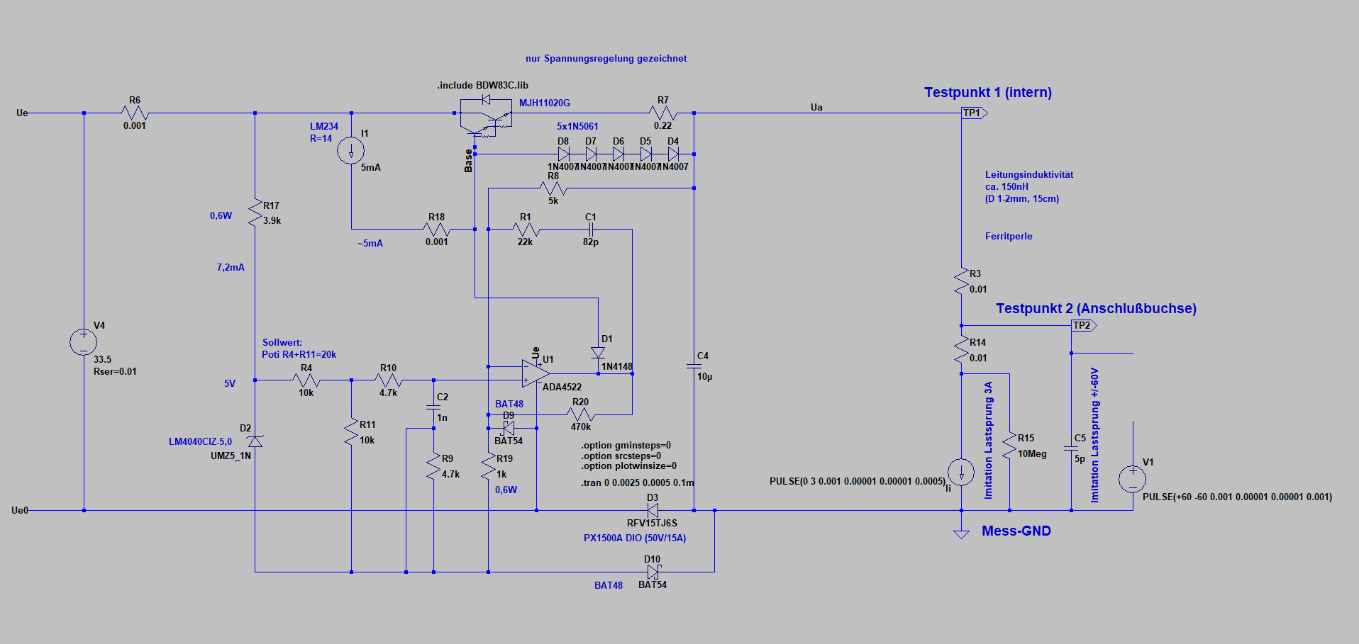
Schaltplan einer Spannungsregelung
nur Spannungsregelung gezeichnet, include BDW3C.lib, Testpunkt 1 (intern), Ue, R6, 0.01, LM234, R14, I1, 5mA, Base, 5x1N5061, R7, 0.2, Ua, TP1, Leitungsinduktivität ca. 150mH (D 1-2mm, 15cm), R17, 0,6W, 3.9k, R10, -5mA, D7, D6, D5, D4, 1N40x, N40x, N40x, N40x, N407, R8, 5k, Ferritperle, R3,
in „Nebenprojekt: Analoges Labornetzteil inkl. Schaltplan und Messungen“ · Projekte & Code · · Schaltpläne
-
Bild
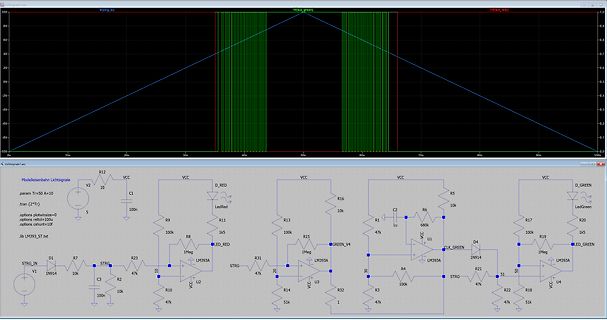
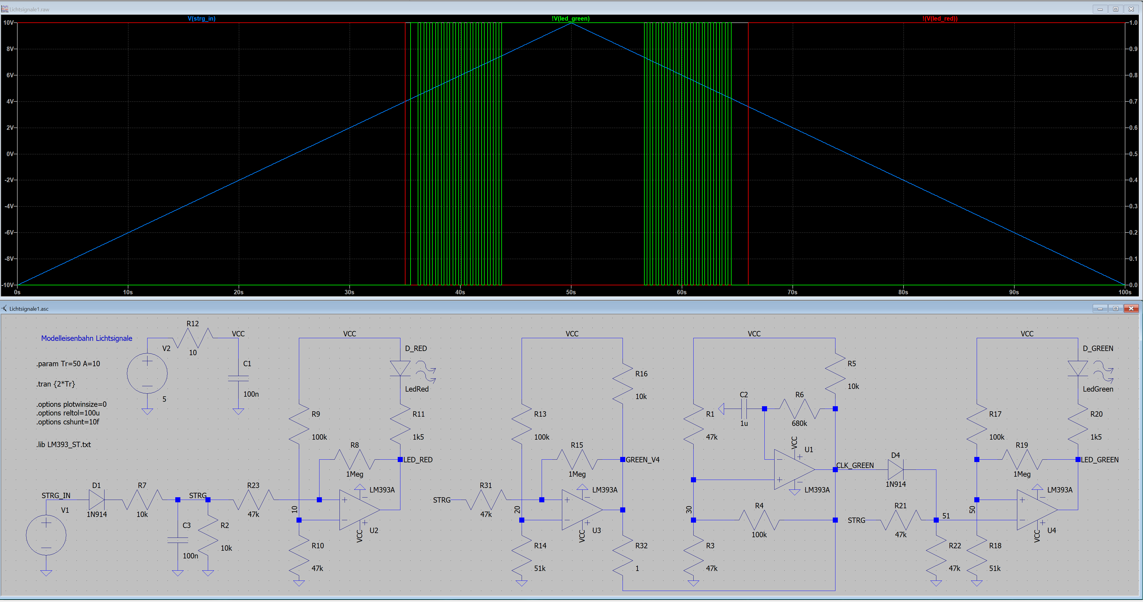
Schaltplan und Oszilloskop-Simulation einer LED-Steuerung
V(strg_in) V(led_green) V(led_red) 10V 5V -5V 0s 10s 20s 30s 40s 50s 60s 70s 80s 90s 100s Modelleisenbahn Lichtsiganle VCC R12 C1 V2 10k 1nF .param Tr=50 A=10 .tran 2T 100n D_RED R11 1k5 R16 10k R9 10k R8 1Meg LED_RED LM393A R10 47k R31 47k R14 51k R13 100k R32 10k R3 47k R4 100k R2 10k R21 47k R23 10k R7 1n914 R30 1Meg R5 10k R6 680k C2 1u U1 LM393A CLK_GREEN D4 1N914 GREEN_V4 R19 100k R20 1k5 LED_GREEN LM393A R18 51k R21 47k U4
in „Lichtsignal für Modelleisenbahn.“ · Analoge Elektronik und Schaltungstechnik · · Screenshots
-
Bild
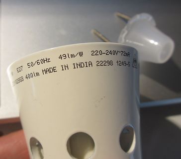
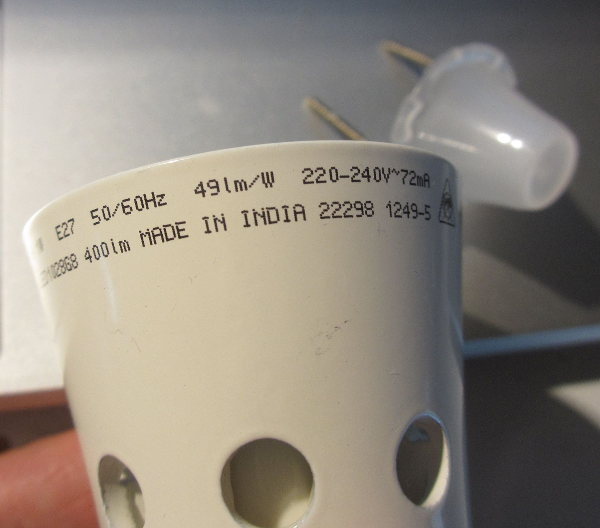
Aufdruck auf einer LED-Leuchtmittel-Fassung
E27 50/60Hz 49lm/W 220-240V~72mA 400lm MADE IN INDIA 22298 1249-5
in „LED-Lampe Ikea - L/R Parallelschaltung?“ · Analoge Elektronik und Schaltungstechnik · · Fotos
-
Bild
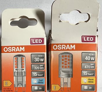
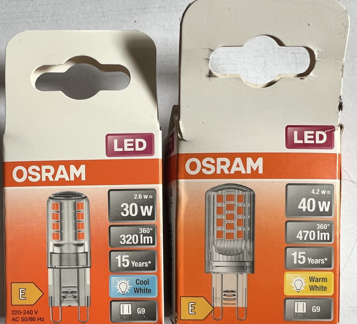
Zwei Packungen Osram LED-Leuchtmittel G9
LED OSRAM 2.6 W = 30 W 360° 320 lm 15 Years* Cool White G9 20-240 V AC 50/60 Hz 4.2 W = 40 W 360° 470 lm 15 Years* Warm White G9
in „Lebensdauer von LED-Lampen“ · Offtopic · · Fotos
-
PDF
Bauteile.pdf
25A 1661 15 ShuntWiderstand R068 68mΩ 1% 82 16 Optokoppler SFH620A-3 5,3kV Pin 99 17 DualKomparator LM393 SMD 17 Treiber IR327 150 19 IGBT IRG4PH30K 720V 10A TO-247 106 20 Mos-Fet STW13NB60 600V 13A 0,54mΩ NKanal 112 21 74xxxx 74HC374ADW SMD 8BitFlipFlop 24 22 Optokoppler BRT23H Pin 15 23 Treiber ST485BDR
in „Elektronik Bauteile Neuwertig , meist Leistungselektronik“ · Markt ·
-
PDF
A_simple_state-of-the-art_spectrometer_for_student.pdf
of the grating of 58l rad: Da ¼ Dk 5:8 10 5 rad. Consequently, 3.45lm. 10 full rotations (Dk ¼ 1000) correspond to Da ¼ 3:3 . In reality, the imaging resolution is limited by aberra- tions4 and we find experimentally FWHM exp 13 lm (see Within this range, we can approximate
in „Physikprojekte“ · Offtopic ·
-
PDF
Elektor_1978-06.pdf
regulators. Pulse Generator. All pulse 999 ms, pulse width isfrom 3 ns video games using hexadecimal The LM 137/LM 237/LM 337 are parameters are programmable to 999 ms both with three digits - width, period, delay, transition of resolution. code. Extremely compact CHIP-8 adjustable 3-terminal negative times
-
PDF
Sinuswechselrichter.pdf
6 0 NEU-IN-FILTERED4 5 D18 R55 GND GND R 1 8 GND R 1 1N4148 5 IC7B 640K C42 7 4 4 6 R 4 1uF 6 5 4 LM393N R 2 IC21 GND KA431 GND ON-LINE R61 C44 K GND 6 8 K 1M R 3 5 1 R60 IC7A 0.22uF R 2 3 10K 1 2 GND LM393N GND U-LINE-RECT Abbildung 32: Beschaltung des netzseitigen Übertragers Der netzseitige Übertrager
in „Wechselrichter Spannung und Frequenz steuerbar für Teichpumpe“ · Haus & Smart Home ·
-
PDF
BU407.pdf
) 7 A C ICP Collector Current (Pulse) 10 A I Base Current 4 A B PC Collector DissipatioC (T =25°C) 60 W T Junction Temperature 150 °C J TSTG Storage Temperature - 65 ~ 150 °C Electrical Characteristics TC=25°C unless otherwise noted Symbol Parameter Test Condition Min. Max. Units ICES Collector Cut-off
in „Leuchtstoffröhren Vorschaltgerät 24V Reparatur-Tipp gesucht“ · Fahrzeugelektronik ·
-
Datei
AddressSanitizer.txt
678 <...> IK1MJL -05 FT8 Decoded: 0 +8.0 1294 <...> DG5MLA JN58 FT8 Decoded: 0 +7.0 441 4U0ITU UR3LM KN89 mag -42 size 1200 ==3269==poisoning: 0x7fffffff8b60 2580 ==3269==unpoisoning: 0x7fffffff8b60 2580 Frame pos: 0.200s Mag: -41.86 Mean: -60.21 sum: -102.06 Max magnitude: -41.9 dB mag -42 size 1200
in „Tipps zur Speicheranalyse gesucht“ · Mikrocontroller und Digitale Elektronik ·
-
PDF
ADC0801_05.pdf
voltage level specifications A converters that use a differentialpotentiometric n Works with 2.5V (LM336) voltage reference D ladder— similar to the 256R products. These converters arechip clock generator C designed to allow operation with the NSC800 and INS8080AV to 5V analog input voltage range with
in „Verständnisfrage zum ADC080x (VIN-MIN/DC-Offset)“ · Analoge Elektronik und Schaltungstechnik ·
-
Bild
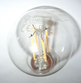
LED-Glühbirne von Ledvance
LEDVANCE 220-240V AC 28988 2700K E27 5.5W 50/60Hz 800lm 450mA Max. Steinere Furt 62 86167 Augsburg WIFI LEDVANCE GmbH
in „LED mit WiFi-Zeichen blinkt - Ausführung für Blinkampel?“ · Haus & Smart Home · · Fotos
-
Bild
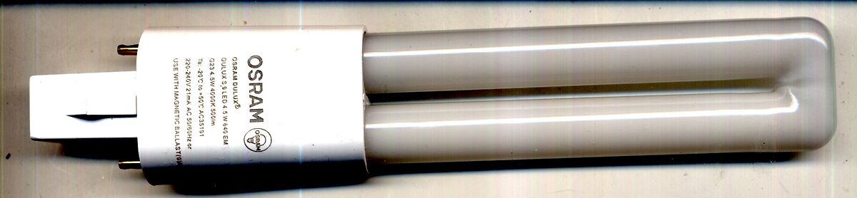
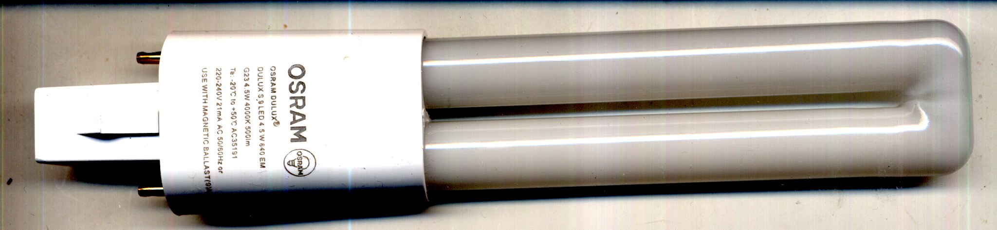
Osram Dulux LED Leuchtstoffröhre
OSRAM DULUX® DULUX S LED 4.5 W 840 EM 234 5W 40K 50lm Ta: -20 C to +50 C AC35191 20-240V 50/60Hz or USE WITH MAGNETIC BALLAST/9W
in „Lupenlampe Fixpoint 77310 Leuchtmittel LED“ · Mechanik, Gehäuse, Werkzeug · · Fotos
-
Bild
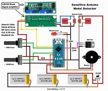
Schaltplan eines Arduino Metal Detektors
LM358 Weak Signal Amplifier, Sensitive Arduino Metal Detector, Search Coils, Circle Ø15cm, 60 turns each, CuL 0.35 mm, Double-D sh., 1µF, Detect Led, 10K(Tune), 10K(Fine), 220R, IRF730, FET N, Buzzer, 110mAh
in „Physikprojekte“ · Offtopic · · Diagramme
-
Bild
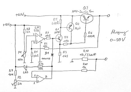
Handgezeichneter Schaltplan einer Spannungsregelung
+60V, R5 470R, Q3 NPN-Darlington, Q2 PNP, Ausgang 0-50V, +12V, R8 2k, LM358, Q1 NPN, R7 1k5, R4 10k, R6 100R, R2 10k, R1 2k5, D1 1N4148, R3 1k5, R10 1R/5watt, P1 10k, R9 10k, R12 10k, LED, P2 2k, R11 1k
in „Spannungsregelung mit Variac und Längstransistor“ · Analoge Elektronik und Schaltungstechnik · · Schaltpläne
-
Bild
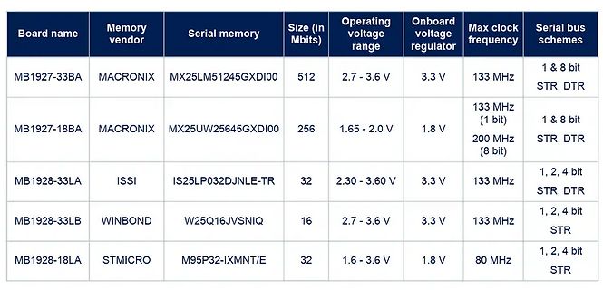
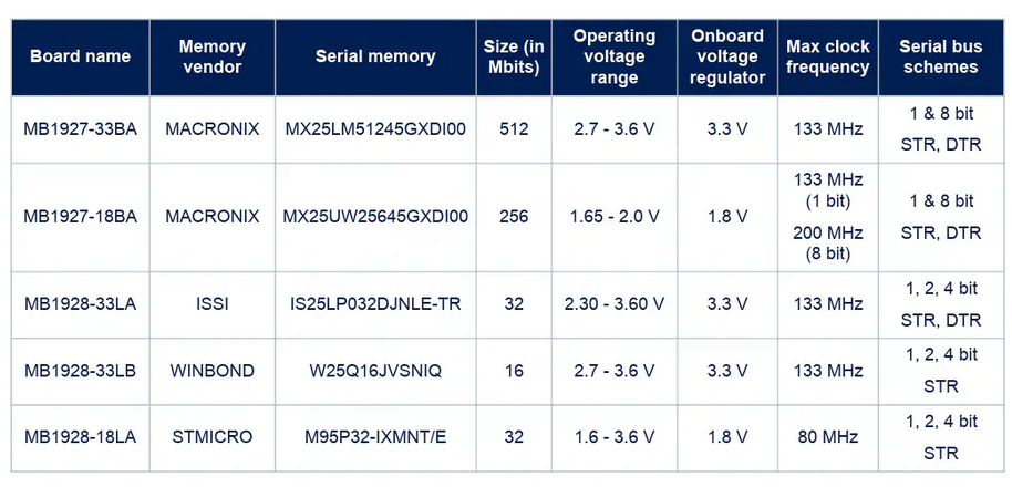
Tabelle mit Spezifikationen von Serial Memory Boards
voltage range Onboard voltage regulator Max clock frequency Serial bus schemes MB1927-33BA MACRONIX MX25LM51245GXDI00 512 2.7 - 3.6 V 3.3 V 133 MHz 1 & 8 bit STR, DTR MB1927-18BA MACRONIX MX25UW25645GXDI00 256 1.65 - 2.0 V 1.8 V 133 MHz (1 bit) 200 MHz (8 bit) 1 & 8 bit STR, DTR MB1928-33LA ISSI IS25LP032DJNLE-TR 32 2.30 - 3.60 V 3.3 V 133 MHz 1, 2, 4 bit STR, DTR MB1928-33LB WINBOND W25Q16JVSNIQ 16 2.7 - 3.6 V 3.3 V 133 MHz 1, 2, 4 bit STR MB1928-18LA STMICRO M95P32-IXMNT/E 32 1.6 - 3.6 V 1.8 V 80 MHz 1, 2, 4 bit STR
in „Neue Bauteile: Verstärker, Drucksensoren und Can-Can“ · Mikrocontroller und Digitale Elektronik · · Screenshots
-
Bild
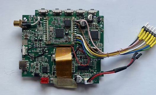
Bestückte Leiterplatte mit Kabeln und Flachbandkabel
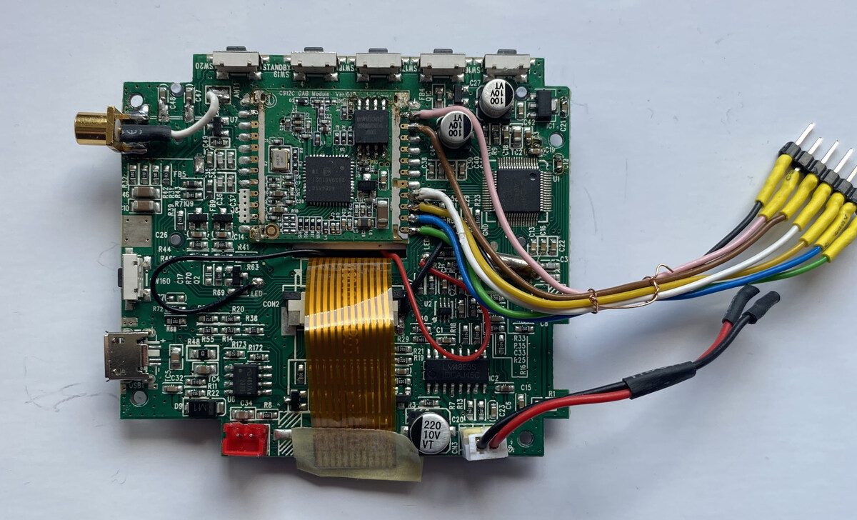
STANDBY 61MS, 100, 10V, LM4863, C26, R44, R4, R69, CON2, R20, R38, R48, R55, R14, R12, R72, C32, C2, C15, C16, C29, C31, C33, C34, C35, C36, C37, C38, C39, C40, C41, C42, C43, C44, C45, C46, C47, C48, C49, C50, C51, C52, C53, C54, C55, C56, C57, C58, C59, C60, C61, C62, C63, C64, C65, C66, C67, C68, C69, C70, C71, C72, C73, C74, C75, C76, C77, C78, C79, C80, C81, C82, C83, C84, C85, C86, C87, C88, C89, C90, C91, C92, C93, C94, C95, C96, C97, C98, C99, C100
in „DAB+ Radiochip“ · Mikrocontroller und Digitale Elektronik · · Platinenfotos
-
PDF
ADC0803_4.pdf
Conversion time fCLK =1MHz 1 66 73 s 1 fCLK Clock frequency 0.1 1.0 3.0 MHz Clock duty cycle 1 40 60 % CS=0, f CLK =1MHz CR Free-running conversion rate INTR tied to WR 13690 conv/s tW(WR)L Start pulse width CS=0 30 ns tACC Access time Output RD CS=0, C L100pF 75 100 ns CL=10pF, R =10k t1H, 0H 3-State
in „Verständnisfrage zum ADC080x (VIN-MIN/DC-Offset)“ · Analoge Elektronik und Schaltungstechnik ·
-
Bild
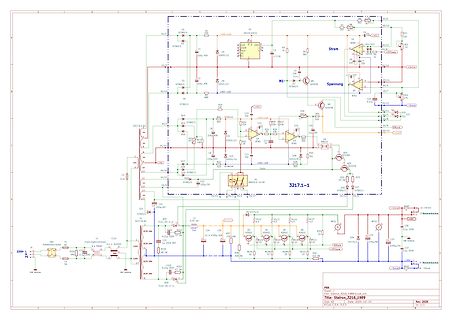
Schaltplan einer elektronischen Schaltung
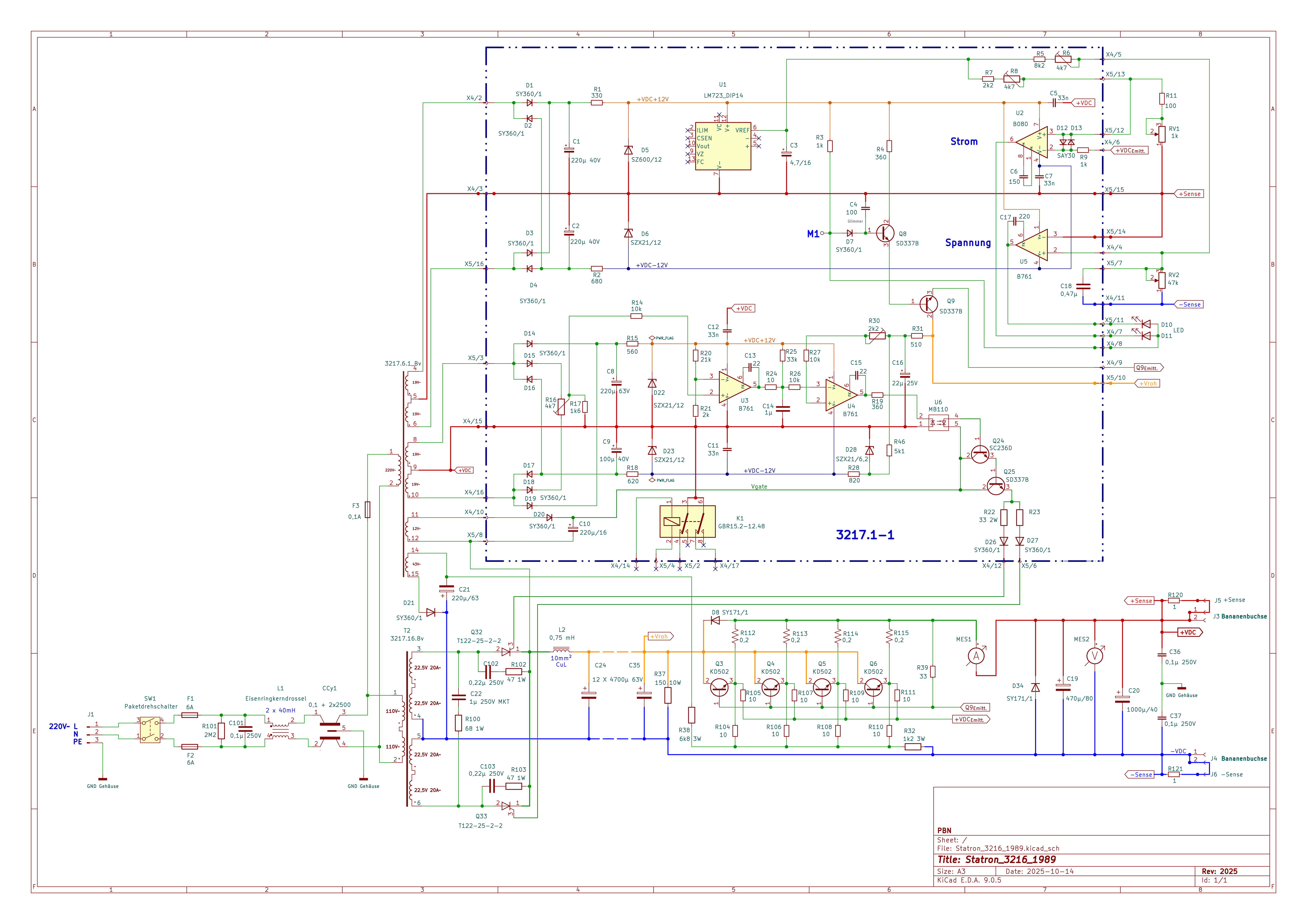
D1 SY360/1, R1 360, U5 LM725, D4 220V, C1 4,7, R2 360, R3 360, R4 360, R5 360, R6 360, R7 360, R8 360, R9 360, R10 360, R11 360, R12 360, R13 360, R14 360, R15 360, R16 360, R17 360, R18 360, R19 360, R20 360, R21 360, R22 360
in „Das Statron 3217/16 Projekt“ · Analoge Elektronik und Schaltungstechnik · · Schaltpläne
-
Bild
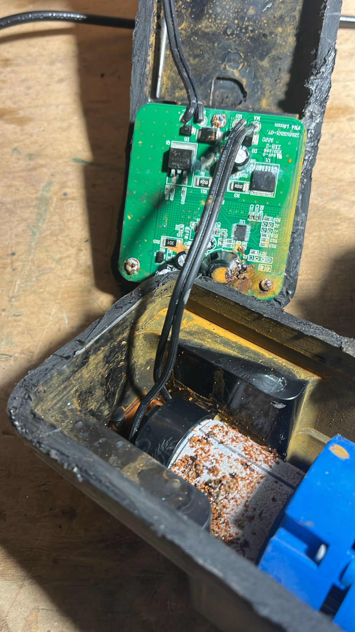
Geöffnetes Gehäuse mit Leiterplatte und Korrosionsspuren
V4 LM16m 22B1026-07 MA R1 C1 U1 R2 C2 R3 C3 R4 C4 J1 J2 J3 J4 J5 J6 J7 J8 J9 J10 J11 J12 J13 J14 J15 J16 J17 J18 J19 J20 J21 J22 J23 J24 J25 J26 J27 J28 J29 J30 J31 J32 J33 J34 J35 J36 J37 J38 J39 J40 J41 J42 J43 J44 J45 J46 J47 J48 J49 J50 J51 J52 J53 J54 J55 J56 J57 J58 J59 J60 J61 J62 J63 J64 J65 J66 J67 J68 J69 J70 J71 J72 J73 J74 J75 J76 J77 J78 J79 J80 J81 J82 J83 J84 J85 J86 J87 J88 J89 J90 J91 J92 J93 J94 J95 J96 J97 J98 J99 J100
in „defekte Pool-Roboter“ · Analoge Elektronik und Schaltungstechnik · · Platinenfotos
-
Bild
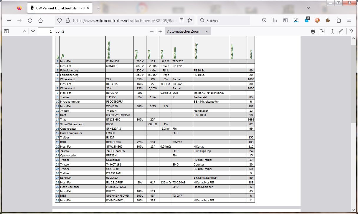
Tabelle mit elektronischen Bauteilen und Spezifikationen
250 35V 1,5A IC #al 8 Treiber BT136-600 RAM 600V 25A 1 $\Omega$ 1691 Optokoppler BT136-600 BT136-600 60M $\Omega$ 5,3 k$\Omega$ 82 Microcontroller W5080 5V 9,7A 1 $\Omega$ 282 74 xxx 74150N Multiplexer 13 RAM BS62LV256SCP70 18 Triac BT136-600 1691 Optokoppler SFH620A-3 Pin SMD 99 Dual Komparator LM393
in „Elektronik Bauteile Neuwertig , meist Leistungselektronik“ · Markt · · Screenshots
-
Bild
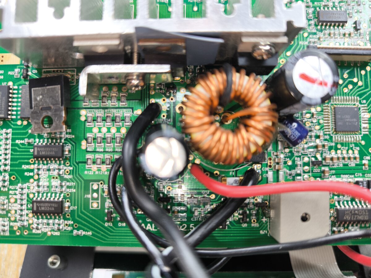
Nahaufnahme einer bestückten Leiterplatte mit Spule und Kondensatoren
LM324A, R22, R24, R26, R7, R9, R10, R12, R13, R14, R15, R17, R21, R23, R24, R25, R26, R27, R28, R30, R31, R32, R33, R34, R35, R36, R37, R38, R39, R40, R41, R42, R43, R44, R45, R46, R47, R48, R49, R50, R51, R52, R53, R54, R55, R56, R57, R58, R59, R60, R61, R62, R63, R64, R65, R66, R67, R68, R69, R70, R71, R72, R73, R74, R75, R76, R77, R78, R79, R80, R81, R82, R83, R84, R85, R86, R87, R88, R89, R90, R91, R92, R93, R94, R95, R96, R97, R98, R99, R100
in „Was ist das für ein Bauteil und wo bekomme ich es?“ · Analoge Elektronik und Schaltungstechnik · · Platinenfotos
-
PDF
Bereitstellungsunterlagen_EGS_AP2.pdf
Digit-Treiber, SMD MAX7219CWG oder SOIC24 (alternativ) technisch vergleichbar 18 1 -A1.K4 IC, Komparator LM2903N oder DIP8 technisch vergleichbar 19 1 IC-Sockel 8-polig DIP8 20 1 -A1.T2 IC, Spannungsregler, +5 V 7805 oder TO220, liegend technisch vergleichbar 21 1 -A1.T1 IC, Spannungsregler LM317 oder TO220
in „Lochraster-Teil der AP2 Winter 25/26“ · Analoge Elektronik und Schaltungstechnik ·
-
PDF
REN_icl7106-07-07s_DST_20251218.pdf
V+ - 0.5V) • INTEGRATION PERIOD lN • AUTO-ZERO CAPACITOR tINT= 1000 x (4/OSC ) 0.01µF < CAZ< 1µF • 60/50Hz REJECTION CRITERION tINT 60Hz or lNT 60Hz = Integer • REFERENCE CAPACITOR 0.1µF < C < 1µF • OPTIMUM INTEGRATION CURRENT REF • V IINT= 4µA COM Biased between Vi and V-. • FULL SCALE ANALOG INPUT
in „Panel-Meter KAIFU FR-4“ · Mikrocontroller und Digitale Elektronik ·
-
PDF
ONJU_Schematic.pdf
VDD_SPI 7 PIJ807 VBUART 5V GND ACA VDD3P3 PI310 8 PIJ308 DC S2SOC VDD3P3 PIU10 VDD_SPI 9 PIJ309 PI60 PID02 PIS204 PIS2023 GPIO0 VDD3P3_CPU PIU04 10 PIJ010 PI 5 P P VDD3P3_RTC PIU02 CC8 502SIP 3OC CO CHIP_PU 4 40CHIP_PU P FH34SRJ-10S-0.5SH(50) 10 µF Boot KMR221GLFS 0.1 µF L3 2.7 nH C20 5 501UIPIO0 C30CO
in „Bitte um Review meiner erweiterten ONYU-Schaltpläne (Bluetooth-Erweiterung mit CSR8635)“ · Mikrocontroller und Digitale Elektronik ·
-
PDF
PMT_handbook_v4E.pdf
described in subsequent sections. Quantity Unit Name Symbol watts [lumens] Radiant flux [Luminous flux] W [lm] Radiant energy [Quantity of light] joules [lumen sec.] J [lm·s] Irradiance [Illuminance] watts per square meter [lux] W/m [lx] Radiant emittance watts per square meter W/m [lm/m ] 2 [Luminous emittance
in „Suche nach geeignetem OpAmp als Impedanzwandler“ · Analoge Elektronik und Schaltungstechnik ·
-
PDF
asus-p701-unlocked.pdf
7 AC_VCC 6 VSUS_ON PMB3904 7 +3VSB 15 +AP2310 +3V SI4835BDY 14 SUSB_ON 21 +VCCP +3V 15 16 +2.5V C LM358+ C 24 VCORE H_CPURST# 29 15 +5V NB 910GM PMBT2222 DOTHAN CPU PM_PWROK 23 26 +1.8V_DUAL 16 VID[0..5] +1.5V LM358+ # 15 +5V AP70T03 25 G S R _ P T _ P (PLT_RST# is 34--41 RTCCLK(=1mS) AC_VCC R later
-
PDF
TF5000CI.pdf
sinking provided, the thermal shutdown circVoltage Range takes over preventing the IC from overheating. LM7805C 5V Considerable effort was expanded to make the LM78XX se- ries of regulators easy to use and mininize the number7812C 12V LM7815C 15V Schematic and Connection Diagrams Metal Can Package TO-3 (K) Aluminum TL/H/7746–2 Bottom View Order Number LM7805CK, LM7812CK or LM7815CK See NS Package Number KC02A Plastic Package TO-220 (T) TL/H/7746–3 Top View Order Number LM7805CT, LM7812CT or LM7815CT See NS Package Number T03B TL/H/7746–1 C1995 National
in „CPU SAA7219 per Jtag auf Basis FT2232H ansprechen - Tool schreiben“ · PC Hard- und Software ·
-
Datei
schaltplan.html
1.6933px" lengthAdjust="spacingAndGlyphs" text-anchor="middle" opacity="0" stroke-opacity="0" id="text53">LM358</text> <g class="stroked-text" id="g118"> <desc id="desc53">LM358</desc> <path d="m 121.0431,82.6793 h -0.6048" id="path54" /> <path d="m 120.4383,82.6793 v -1.27" id="path55" /> <path d="m 121.4664,82.6793
in „Benutzt hier jemand "Circuit Diagram"?“ · PC Hard- und Software ·
-
PDF
Stenorette_2010_SW.pdf
uerden und darfl bei einer seit-Iichen Belastung EinsLetluna: Durch Biegen des Justagelupp"n"f von 0,60 N (1 N = 102 p) an der Riemenscheibe nichl am Getrieb6hebel chen. als 0,5 mm in Zugrichtung des Riemens abue.i- ] Ausbau des Laufuerkes 5topeinstelluno 3 B.Lechschrarbenlherausdrehen. Antriebsriemen
in „Recht auf Reparatur“ · Offtopic ·
-
PDF
EA8252.pdf
FSHORT VOUT= 0V 200 KHz High Side MOSFET On-Resistance R DS(ON)-HM 120 mΩ Low Side MOSFET RDS(ON)-LM 100 mΩ On-Resistance High Side MOSFET ILIM-HM 2.5 4 A Current Limit High Side MOSFET I VRUN= 0V, VSWITCH 1 10 uA Leakage Current LEAK-HM = 0V RUN Pin Input Low Voltage VRUN-L 0.4 V RUN Pin Input High
in „Kurioser DC-DC Step Down Converter“ · Analoge Elektronik und Schaltungstechnik ·
-
PDF
Intersil_ICL8052_ICL8068_ICL71C03.pdf
DIGIT BLANKING ON OVERRANGE 16 ICL8052A/ICL71C03, ICL8068A/ICL71C03 +5V 16kΩ 1kΩ 56kΩ 2 + 8 7 0.22µF LM311 - 1 30kΩ 3 4 R fOSC = 0.45/RC 16kΩ 37.5kΩ 390pF C 100pF FIGURE 12. CMOS OSCILLATOR FIGURE 13. LM311 OSCILLATOR D S 2N5461 D S 2N5458 0.22µF +15V -15V 100K -BUF IN BUF OUT -INT IN INT OUT REF OUT 6
-
PDF
Orion_Rev_3.0__1_.pdf
R14 VCCINT VCCIO7 H18 AJ23 GND GND R17 C138 C98 C67 C47 C68 C48 C134 C120 C45 C115 C42 C131 C100 C60 R16 VCCINT VCCIO7 H19 AJ26 GND GND R19 100NF 0402 100NF 0402 100NF 0402 100NF 0402 100NF 0402 100NF 0402 1100NF 040200NF 0402 100NF 0402 10NF 0410NF 0402 1NF 0402 1NF 0402 R18 H21 AJ29 R21 2 2 2 2 2
in „Suche Firma die für Privat BGA FPGA reballing macht“ · Markt ·
-
PDF
T-3.pdf
and 78rpm 4-6 Wow and Flutter Less than 0.15% WRMS (JIS WTD) with 33 / rpm3 4-7 S/N Ratio More than 60dB (DIN-B) 4-8 Pitch Controls +/- 8%,+/- 12%,+/- 20%. 4-9 Starting Torque More than 1.6 kgf.cm 4-10 Braking System Electronic brake 4-11 Starting Time Less than 1 sec. 4-12 Braking Time Less than 1 sec
in „Eprom von Denon DJ Laufwerk defekt Winbond 78e52“ · Mikrocontroller und Digitale Elektronik ·
-
PDF
6ff78f.pdf
of the reverb created by artificial echo chambers, as used on classic recordings of the '50s and '60s. Specifications For the more technical-minded, here are some detailed specifications for the MultiMix’s operating levels. Input Channels Mic In Sensitivity Range: -60dBu to –10dBu nominal, +5dBu Maximum Line In Sensitivity Range: -40dBu to -+10dBu nominal, +25dBu maximum Mic/Line Gain Range: +10 to +60dB Equalization High-Pass Filter: 75Hz, 18dB/octave High Shelving: 12kHz, +/- 15dB Mid Bandpass/Band Reject: 2.5 kHz, +/- 15dB Low Shelving: 80Hz, +/- 15dB Aux Sends Aux Send A & B Gain Range: -Ü to +
in „Mischpult "Alesis Multimix 8" (Knallen auf allen Ausgängen)“ · Analoge Elektronik und Schaltungstechnik ·
-
PDF
sharp_r733.pdf
inutilisée. 34 R53 ENTREE Signal provenant du commutateur sensitif. Lorsqu’un des commutateurs sensitifs SW60-SW63 est effleuré, un signal correspondant de R60, R61, R62, et R63 est entré dans R53. Lorsqu’aucune touche n’est effleurée, le signal est maintenu au niveau “H”. 35 R60 SORTIE Signal d’échantillonnage
in „Fragen zu einem Trafo einer Sharp R733(W) Mikrowelle“ · Analoge Elektronik und Schaltungstechnik ·
-
PDF
pm2534ocr.pdf
So 4 o2 oe| o= ot of a n > +=] +a] r'] +* +n a1= + + L1a) +] +e 'a) Ld o o a oov es of — oo — ob = 60 — ob a 6o et op — of — bb st oD a e e c-t pp80 oo) ceeD Cee cC-- ces optetpocee ceeD op=o “ Cc-- is w e w e7 n bok w e w e ke n ebk nme e m ee mn w e fe 7 os n e 7) bb fe > S = i ‘ l x x a ES S 5 3 —
in „Pjilips PM2519“ · Markt ·
-
PDF
pm2519ocr.pdf
40 6B for ac. signals at 50 Hz = 1 % M R R : > 100 GB for duc. signals, > 100 eB for dc. signals 50/60 Hz Maximum CM-voltage +280 V, 354 Vpeak Response time # 1 . s including renging <0.5 soxcluding ranging Maximum input vottage between :Hland LO 1000 Vims** Hi and earth 1000 Vrms** L O andearth 250 V
in „Pjilips PM2519“ · Markt ·
-
PDF
53131a_53132a_bedienungsanleitung_deutsch_komprimiert.pdf
bilität, Opttion OlO °* 3,0-GHz-HF-Eingangskanall ( Kananal), ,ptition30 * *Rückwandanschlüsse,, Optition60 ® G te leinbausatz,z, Opttion IC Unt tütz nterstutzung °* jährigege HP-Repar turga antie,e, OpttionW50 °* jährigege HP-Kalibriergarantie,e, Opttion W 52 Handbüch Handbueher e Ohnee B edienungsanleitung
in „[V] HP/Agilent 53131a/53132a Bedienungsanleitung deutsch“ · Markt ·
-
PDF
technical.pdf
(6.18) h 12 3 4 C 137 10 5 1 BDF5: I n+1 = · ·Vn+1 − 5·V n 5·V n−1 − ·Vn−2+ ·Vn−3 − ·Vn−4 (6.19) h 60 3 4 5 C 147 15 20 15 6 1 BDF6: I n+1 = · ·Vn+1 − 6·V n ·Vn−1 − ·Vn−2 + ·Vn−3 − ·Vn−4 + ·Vn−5 h 60 2 3 4 5 6 (6.20) The integration formula contains the coefficients c = a /b /h and d = −1/b /h . Fur- i
-
PDF
FT_1984_Heft_01_OCR.pdf
lierten Leistung von 300 kVA, bzw. einem stufe ist eine 5CX3000A verwendet. Alle stem Telefunken) LM-MW- und KW-Sen- Netzausschaltstrom von 25 kA. Die PANTEL-Sender können , falls notwen der an, die allesamt eine revolutionäre AbStromversorgung des Senders zeichnet dig, fernbedient und damit unbemannt
in „[VS] verschenke Taststift“ · Markt ·
-
PDF
pdftex-a.pdf
. . . .59 . . . . 4.21.7 \pdfprimitive . . . . . . . . . . . . . . . . . . . . . . . . . . . . . .60 . . . . 4.22 Typesetting . . . . . . . . . . . . . . . . . . . . . . . . . . . . . . . . . . 60. . . . . . 4.22.1 \pdfinsertht . . . . . . . . . . . . . . . . . . . . . . . . . . . . . . 60. . . . . 4.22.2 \pdflastxpos, \pdflastypos . . . . . . . . . . . . . . . . . . . . . . . 60. . . 4.22.3 \pdfsavepos . . . . . . . . . . . . . . . . . . . . . . . . . . . . . . .60 . . . . 4.22.4 \quitvmode . . . . . . . . . . . . . . . . . . . . . . . . . . . . . . . 60. . . . . 5 4.22.5 \vadjust
-
PDF
Modulkarte__2_11_07__Netzeinschub_regelbar.pdf
V 5 V B elastu n g UA lA p UA 1A p UA h p UA 1A p gemessen RL 90Q/25W e rre c h n e t gemessen RL 60Q/25W e rre c h n e t gemessen RL 30Q/25W e rre c h n e t gemessen RL 25Q/25W e rre c h n e t gemessen RL 20Q/25W e rre c h n e t gemessen RL 15Q/25W e rre c h n e t gemessen RL 10Q/25W e rre c h n e
in „suche Infos zu Trafo aus der KE-Ausbildung (Bundespost)“ · Analoge Elektronik und Schaltungstechnik ·