-
PDF
LM317_Datenblatt.pdf
page 18/34 LM217, LM317 TO-220FP type A package information Table 9. TO-220FP package mechanical data mm Dim. Min. Typ. Max. A 4.4 4.6 B 2.5 2.7 D 2.5 2.75 E 0.45 0.7 F 0.75 1 F1 1.15 1.70 F2 1.15 1.70 G 4.95 5.2
in „12V Membranpumpe (KNF) läuft nur mit halber Leistung bei interner 3V-Steuerspannung (LM317)“ · Analoge Elektronik und Schaltungstechnik ·
-
PDF
LM317.PDF
http://onsemi.com 4 LM317 4.0 ) ( 0.4 E ) N 0.2 ( 3.0 H N C 0 I = 0.5 A R T = 25⋅C G L R J T -0.2 C 2.0 O I = 1.5 A U V L T 150⋅C U -0.4 U T Vin 15 V ,t O -0.6 Vout= 10 V o 1.0 55⋅C ,t I o-0.8 V -1.0 0 -50 -25 0 25 50 75 100
in „Spannungsregler für Kleinverbraucher bei 1,2V gesucht“ · Analoge Elektronik und Schaltungstechnik ·
-
Bild
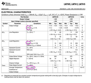
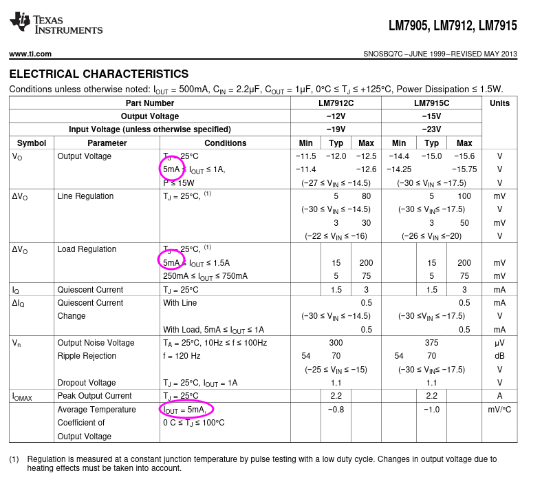
Elektrische Kennwerte eines Datenblatts von Texas Instruments
TEXAS INSTRUMENTS LM7905, LM7912, LM7915 ELECTRICAL CHARACTERISTICS LM7912C LM7915C Output Voltage -12V -15V -19V -23V Vo Output Voltage 25°C -11.5 -12.0 -12.5 -14.4 -15.0 -15.6 V 5mA Iout <= 1A -11.4 -12.6 -15.75 V P <=
in „7915 gibt 18V ab“ · Analoge Elektronik und Schaltungstechnik · · Screenshots
-
Bild
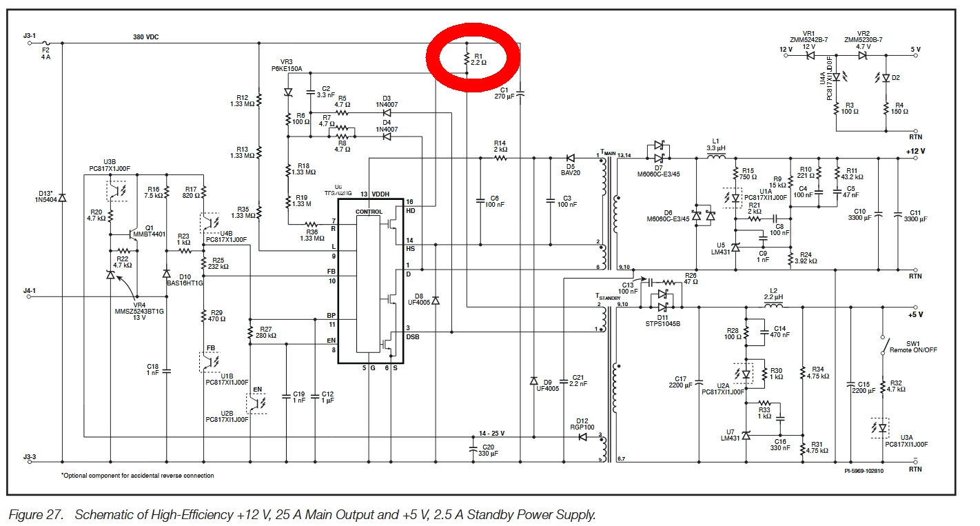
Schaltplan eines Netzteils
DSB 5 6 S 14-25 V U18 PC81X1J00F FB VR4 MMSZ43BT1G 13 V C18 22 µF C20 330 µF U3A PC81X1J00F R30 4.75 kΩ R32 2.2 kΩ C17 2200 µF C14 470 nF R28 100 Ω D11 STPS1045B U5 LM431 C5 100 nF C6 100 nF C3 100 nF L1 3.3 µH R15 75 Ω R9 10 kΩ R10 43.2 kΩ U4A PC81X1J00F C7 47 nF C11 3300 µF C10 3300 µF C8 100 nF R24 3.92 kΩ U5 LM431 R29 1 kΩ U7 LM431 C16 320 nF R31 4.75 kΩ RTN +12 V +5 V RTN RTN
in „Netzteil Lenovo 92z ThinkCentre Type 3396 defekt“ · Analoge Elektronik und Schaltungstechnik · · Schaltpläne
-
Bild
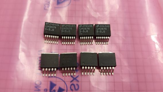
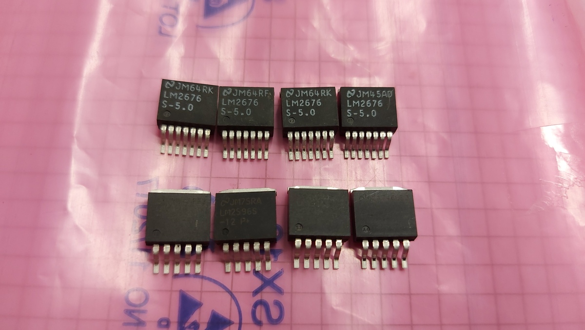
Acht integrierte Schaltkreise auf rosa Untergrund
JM64RK LM2676 S-5.0 JM64RF LM2676 S-5.0 JM64RK LM2676 S-5.0 JM45AD LM2676 S-5.0 JM75RA LM2596S -12 P
in „[V] Konvolut Schaltregler: 4x LM2676S-5.0 , 4x LM2596S-12 , 2St. DC/DC Buck LM2675 MX-ADJ SO8 (11€)“ · Markt · · Fotos
-
PDF
Bauteile.pdf
17N80C3 800V 17A NKanal 25 46 Bauteil Mos-Fet IRL2910PBF 100V 55A NKanal 47 Bauteil Mos-Fet IRF2805 55V 75A 47 mΩ 3 48 Bauteil Mos-Fet STP12NM50 N 500V 12A 350 mΩ N Kanal 37 49 Bauteil NPNTransistor BDX37 75V 5A NPNTransistor 12 50 Bauteil Optokoppler SFH620A-3 5,3kV Pin 99 51 Bauteil Optokoppler BRT23H Pin
-
PDF
fsp_technology_fsp202-4fs01_runtkb074wjqz_psu.pdf
1 2 3 4 5 6 7 8 I HOT CHASSIS COLD CHASSIS " " " " SCK15046 SF46G 47uF,200V 47uF,200V SC101 F101 8LM0265901 8LM0289201 TH101 P 8LM0289201 8TI0120601GP MUR460 BEAD + FB101 T101:12 D901 C901 C902 70V/1.8A LF103:1 LF101:2 L603:1 L601:1 L601:3 D601 FB601 B JUMP V-LED SC101:3 L 4 SF46G T4AH/250V " 4 + +
in „Welche Diode ist das?“ · Analoge Elektronik und Schaltungstechnik ·
-
Bild
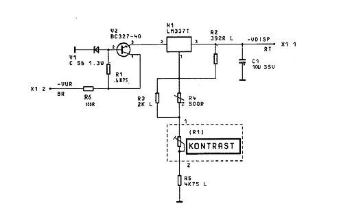
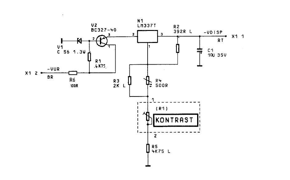
Schaltplan einer Spannungsregelung mit LM37T
V2 BC327-40 3 2 R2 392R L -VDISP X1 1 N1 LM337T 3 2 1 V1 C 56 1.3W R1 .4K75 2 X1 2 VUR BR R6 100R R3 2K L R4 50R C1 10U 35V (R1) KONTRAST 1 2 R5 4K75 L
in „CMS54 - Impulsgeber ruiniert, brauche Widerstandswert.“ · HF, Funk und Felder · · Schaltpläne
-
Bild
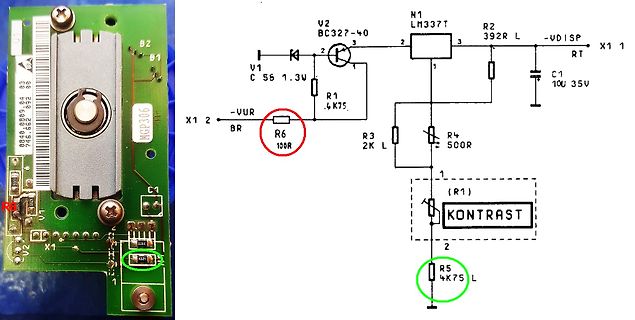
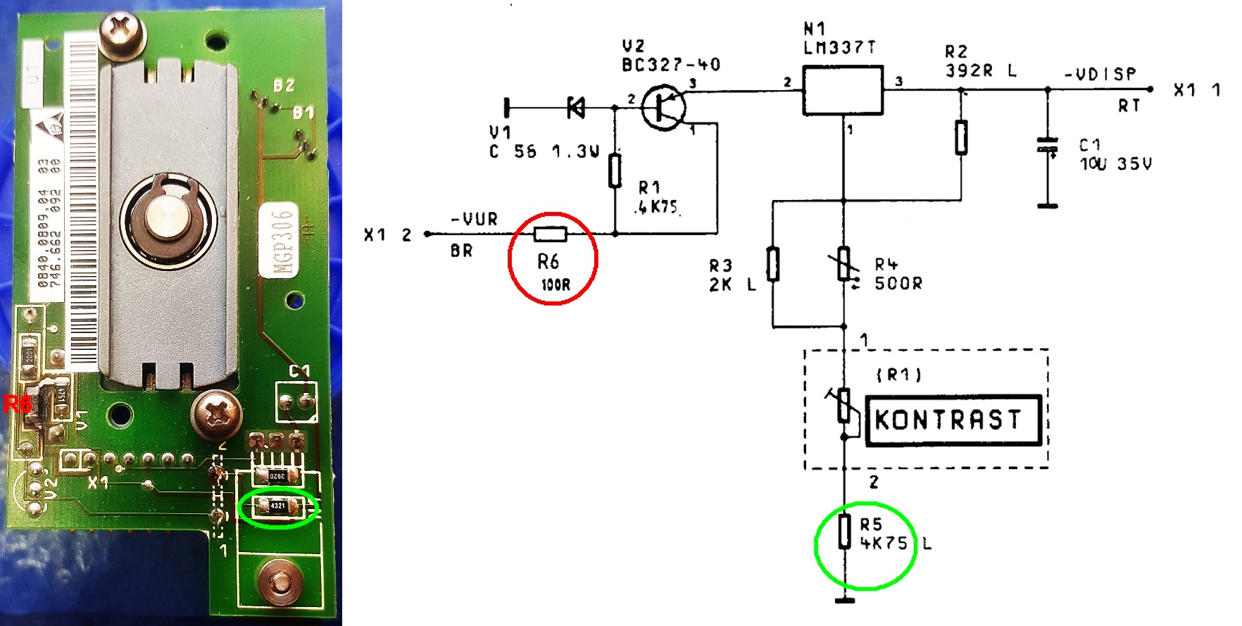
Foto einer Leiterplatte und Schaltplan
B2, B1, MGP306, C1, U1, U2, X1, R2, V1, V2, BC327-40, LM37, R2 392R, -VDISP, RT, X1 1, C1 10U 35V, R1 .4K75, R3 2K L, R4 500R, (R1) KONTRAST, R5 4K75 L, R6 10R, -VUR, X1 2, BR
in „CMS54 - Impulsgeber ruiniert, brauche Widerstandswert.“ · HF, Funk und Felder · · Schaltpläne
-
PDF
ADC0803_4.pdf
hysteresisT(V +)T(V –) 0.6 1.3 2.0 V DC VOL Logical “0” clock R output voltage OL = 360 A, VCC= 4.75VDC 0.4 V DC V Logical “1” clock R output voltage I = –360 A, V = 4.75V 2.4 V OH OH CC DC DC Data output and INTR VOL Logical “0” output voltage Data outputs OL = 1.6mA, VCC= 4.75VDC 0.4 V DC INTR outputs OL = 1.0mA, VCC= 4.75VDC 0.4 V DC I = –360 A, V = 4.75V 2.4 V Logical “1” output voltage OH CC DC V OH OH = –10 A, VCC = 4.75DC 4.5 DC IOZL 3-state output leakage V OUT= 0VDC , CS = logical “1” –3 ADC IOZH 3-state output
in „Verständnisfrage zum ADC080x (VIN-MIN/DC-Offset)“ · Analoge Elektronik und Schaltungstechnik ·
-
PDF
A_simple_state-of-the-art_spectrometer_for_student.pdf
of the grating of 58l rad: Da ¼ Dk 5:8 10 5 rad. Consequently, 3.45lm. 10 full rotations (Dk ¼ 1000) correspond to Da ¼ 3:3 . In reality, the imaging resolution is limited by aberra- tions4 and we find experimentally FWHM exp 13 lm (see Within this range, we can approximate
in „Physikprojekte“ · Offtopic ·
-
PDF
ADC0801_05.pdf
Hysteresis 0.6 1.3 2.0 VDC (VT+)−(VT−) = VOUT (0) Logical “0” CLK R Output IO 360 µA 0.4 VDC Voltage V = 4.75 V CC DC VOUT (1) Logical “1” CLK R Output IO= −360 µA 2.4 VDC Voltage V CC= 4.75 VDC DATA OUTPUTS AND INTR VOUT (0) Logical “0” Output Voltage Data Outputs IOUT =1.6 mA, VCC= 4.75 VDC 0.4 VDC = = INTR Output IOUT 1.0 mA, VCC 4.75 VDC 0.4 VDC VOUT (1) Logical “1” Output Voltage IO= −360 µA, VCC= 4.75 VDC 2.4 VDC VOUT (1) Logical “1” Output Voltage IO=−10 µA, VCC =4.75 VDC 4.5 VDC OUT TRI-STATE Disabled Output V OUT= 0 VDC −3 µADC
in „Verständnisfrage zum ADC080x (VIN-MIN/DC-Offset)“ · Analoge Elektronik und Schaltungstechnik ·
-
PDF
Elektor_1978-06.pdf
regulators. Pulse Generator. All pulse 999 ms, pulse width isfrom 3 ns video games using hexadecimal The LM 137/LM 237/LM 337 are parameters are programmable to 999 ms both with three digits - width, period, delay, transition of resolution. code. Extremely compact CHIP-8 adjustable 3-terminal negative times
-
PDF
Bauteile.pdf
25A 1661 15 ShuntWiderstand R068 68mΩ 1% 82 16 Optokoppler SFH620A-3 5,3kV Pin 99 17 DualKomparator LM393 SMD 17 Treiber IR327 150 19 IGBT IRG4PH30K 720V 10A TO-247 106 20 Mos-Fet STW13NB60 600V 13A 0,54mΩ NKanal 112 21 74xxxx 74HC374ADW SMD 8BitFlipFlop 24 22 Optokoppler BRT23H Pin 15 23 Treiber ST485BDR
in „Elektronik Bauteile Neuwertig , meist Leistungselektronik“ · Markt ·
-
Bild
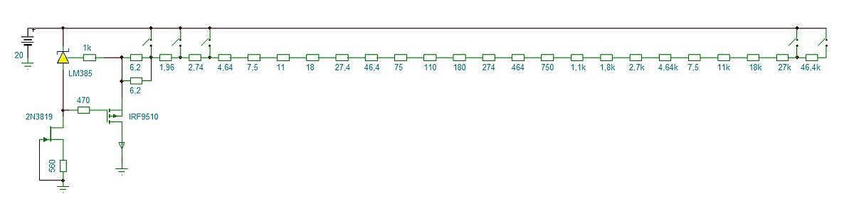
Schaltplan einer Widerstandskette mit MOSFET-Steuerung
20 LM385 1k 6,2 1,96 2,74 4,64 7,5 11 18 27,4 46,4 75 110 180 274 464 750 1,1k 1,8k 2,7k 4,64k 7,5 11k 18k 27k 46,4k 2N3819 470 IRF9510 560
in „LED Tester nach Arno - Vorlage“ · Analoge Elektronik und Schaltungstechnik · · Schaltpläne
-
PDF
BU407.pdf
Current Gain Bandwidth Product VCE = 10V,CI = 0.5A 10 MHz t Turn OFF Time OFF : BU407 IC= 5A, B = 0.5A 0.75 µs : BU407H IC= 5A, B = 0.8A 0.4 µs ©2000 Fairchild Semiconductor International Rev. A, February 2000 B U Typical Characteristics 4 0 7 4 5 0 0m A 180 A IB= 160mA 1000 7 IB= 20 IB= m A V = 5V IB= 10
in „Leuchtstoffröhren Vorschaltgerät 24V Reparatur-Tipp gesucht“ · Fahrzeugelektronik ·
-
Bild
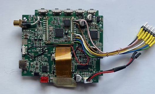
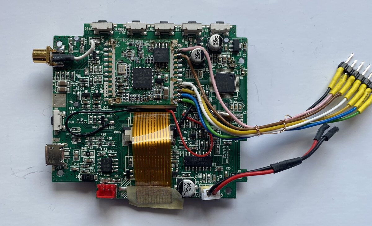
Bestückte Leiterplatte mit Kabeln und Flachbandkabel
STANDBY 61MS, 100, 10V, LM4863, C26, R44, R4, R69, CON2, R20, R38, R48, R55, R14, R12, R72, C32, C2, C15, C16, C29, C31, C33, C34, C35, C36, C37, C38, C39, C40, C41, C42, C43, C44, C45, C46, C47, C48, C49, C50, C51, C52, C53,
in „DAB+ Radiochip“ · Mikrocontroller und Digitale Elektronik · · Platinenfotos
-
Bild
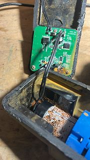
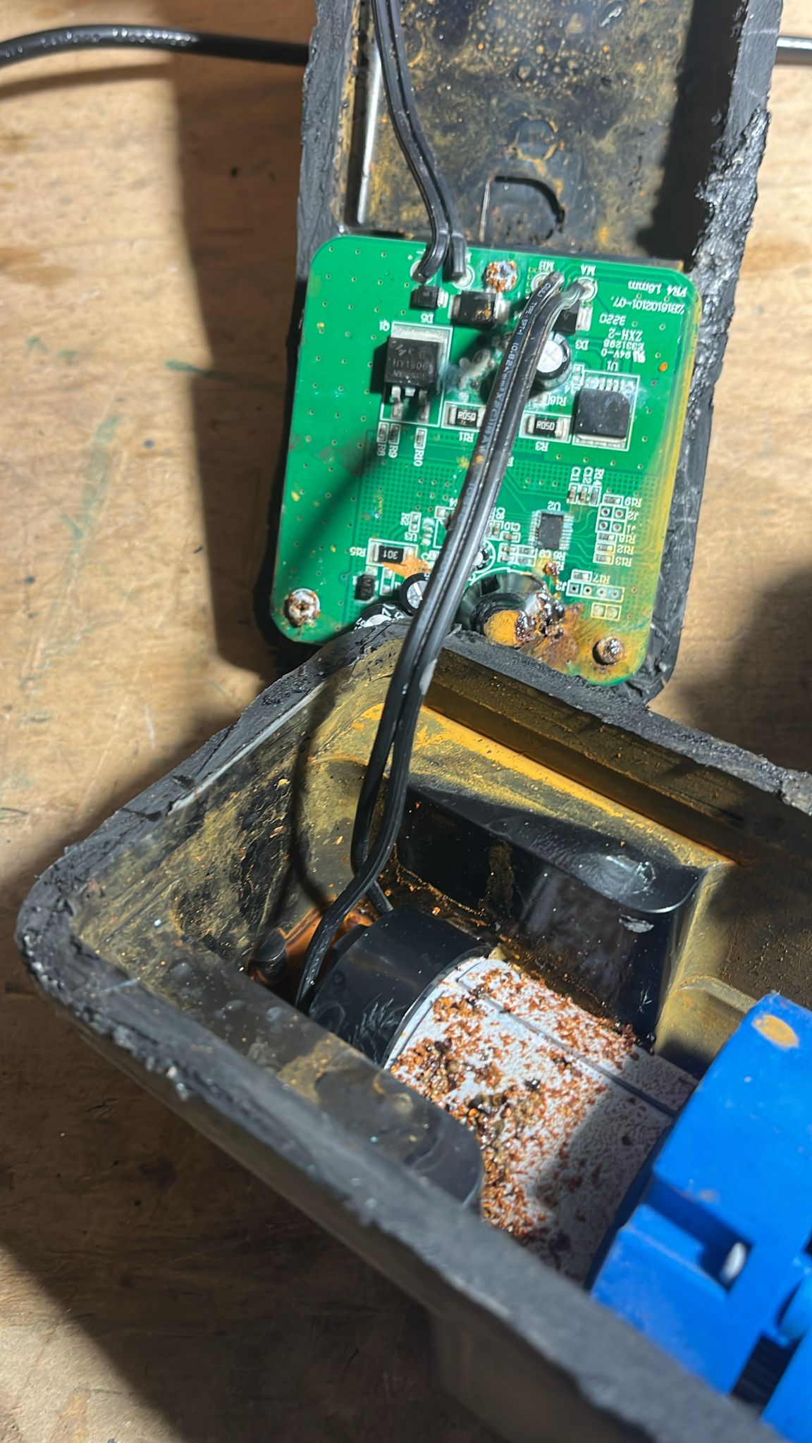
Geöffnetes Gehäuse mit Leiterplatte und Korrosionsspuren
V4 LM16m 22B1026-07 MA R1 C1 U1 R2 C2 R3 C3 R4 C4 J1 J2 J3 J4 J5 J6 J7 J8 J9 J10 J11 J12 J13 J14 J15 J16 J17 J18 J19 J20 J21 J22 J23 J24 J25 J26 J27 J28 J29 J30 J31 J32 J33 J34 J35 J36 J37 J38 J39 J40 J41
in „defekte Pool-Roboter“ · Analoge Elektronik und Schaltungstechnik · · Platinenfotos
-
PDF
100807728a.pdf
® Product Manual Standard models ST2000LM015 ST1000LM048 ST500LM030 100807728, Rev. A September 2016 Document Revision History Revision Date Pages affectedand Description ofchange Rev. A 09/06/2016 Initial release a © 2016SeagateTechnologyLLC.Allrightsreserved
in „Komponenten für Low Power Fileserver?“ · PC Hard- und Software ·
-
Bild
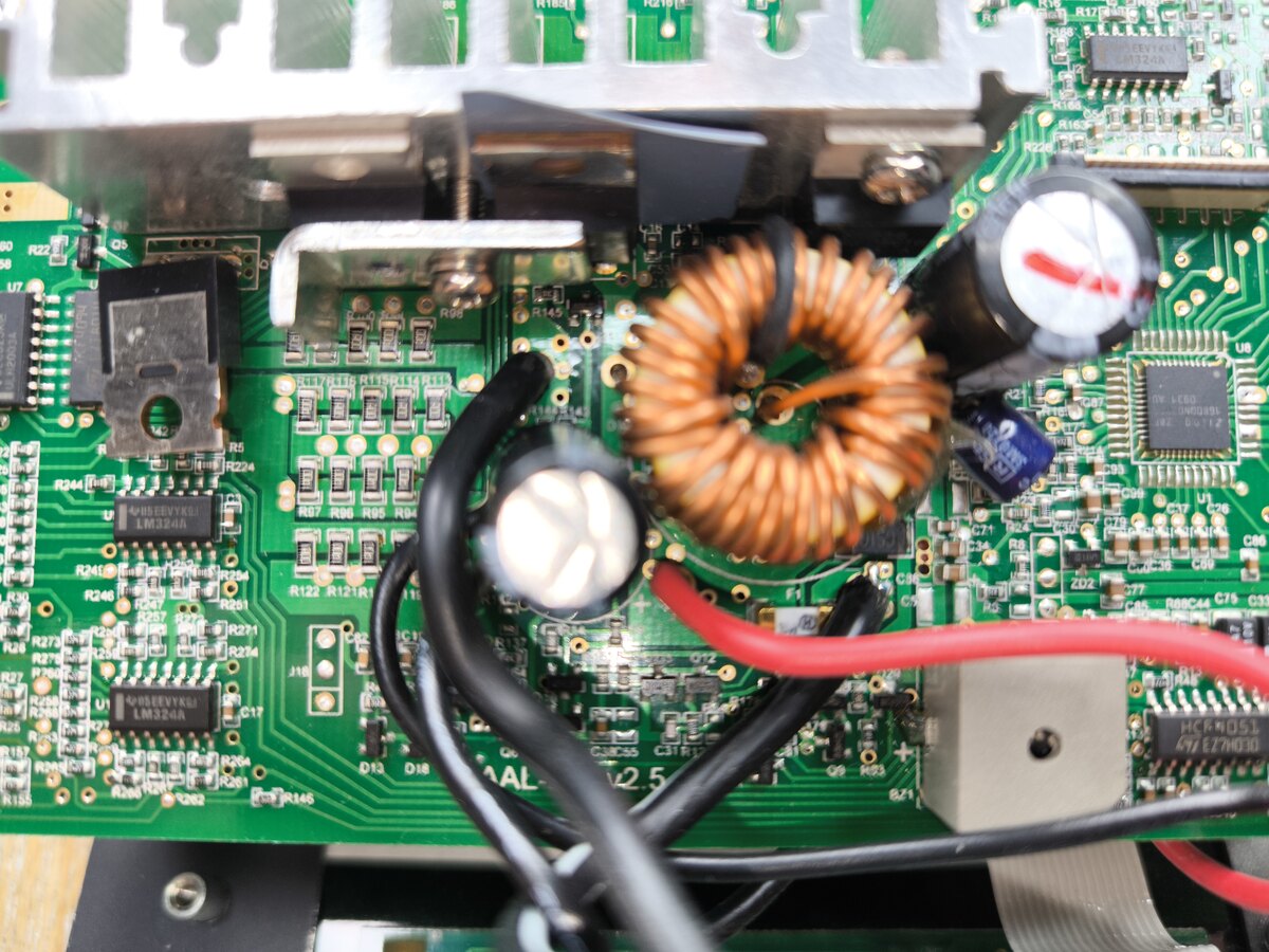
Nahaufnahme einer bestückten Leiterplatte mit Spule und Kondensatoren
LM324A, R22, R24, R26, R7, R9, R10, R12, R13, R14, R15, R17, R21, R23, R24, R25, R26, R27, R28, R30, R31, R32, R33, R34, R35, R36, R37, R38, R39, R40, R41, R42, R43, R44, R45, R46, R47, R48, R49, R50, R51
in „Was ist das für ein Bauteil und wo bekomme ich es?“ · Analoge Elektronik und Schaltungstechnik · · Platinenfotos
-
PDF
asus-p701-unlocked.pdf
7 AC_VCC 6 VSUS_ON PMB3904 7 +3VSB 15 +AP2310 +3V SI4835BDY 14 SUSB_ON 21 +VCCP +3V 15 16 +2.5V C LM358+ C 24 VCORE H_CPURST# 29 15 +5V NB 910GM PMBT2222 DOTHAN CPU PM_PWROK 23 26 +1.8V_DUAL 16 VID[0..5] +1.5V LM358+ # 15 +5V AP70T03 25 G S R _ P T _ P (PLT_RST# is 34--41 RTCCLK(=1mS) AC_VCC R later
-
Datei
schaltplan.html
1.6933px" lengthAdjust="spacingAndGlyphs" text-anchor="middle" opacity="0" stroke-opacity="0" id="text53">LM358</text> <g class="stroked-text" id="g118"> <desc id="desc53">LM358</desc> <path d="m 121.0431,82.6793 h -0.6048" id="path54" /> <path d="m 120.4383,82.6793 v -1.27" id="path55" /> <path d="m 121.4664,82.6793
in „Benutzt hier jemand "Circuit Diagram"?“ · PC Hard- und Software ·
-
Datei
AddressSanitizer.txt
poisoning: 0x7fffffff8b60 2580 ==3269==unpoisoning: 0x7fffffff8b60 2580 Frame pos: 0.200s Mag: -26.75 Mean: -56.80 sum: -83.55 Max magnitude: -25.9 dB mag -27 size 1200 ==3269==poisoning: 0x7fffffff8b60 2580 ==3269==unpoisoning: 0x7fffffff8b60 2580 Frame pos: 0.200s Mag: -27.46 Mean: -56.59 sum: -84.05
in „Tipps zur Speicheranalyse gesucht“ · Mikrocontroller und Digitale Elektronik ·
-
PDF
Intersil_ICL8052_ICL8068_ICL71C03.pdf
. . . . . . . . . . . . . . . . . . . . . . . . . . . . CERDIP Package. . . . . . . . . . . . . . .75 . 20 Differential Input Voltage 14 Ld PDIP Package . . . . . . . . . . . 100 . N/A (8068A). . . . . . . . . . . . . . . . . . . . . . . . . . . . . . . . . . . . . . . . . ±30V 28 Ld PDIP Package . .
-
PDF
6ff78f.pdf
” Outputs Main Mix, Ctrl Room, Ext Aux Send Level: +4dBu nominal, +20dBu maximum Headphone Output: 75 ohm output impedance >105mW into 75 ohms, >40mW into 600ohms RCA Outputs Tape Out Level: -10dBV nominal, +5dBV maximum DISASSEMBLY PROCEDURES 1. REMOVAL OF TOP PANEL/BOTTOM PANEL (Fig1) (A) TAKE OUT
in „Mischpult "Alesis Multimix 8" (Knallen auf allen Ausgängen)“ · Analoge Elektronik und Schaltungstechnik ·
-
PDF
Sinuswechselrichter.pdf
die Schaltung zur Erzeugung der Versorgungsspannun- gen. In der USV übernehmen Festpannungsregler (LM340 und 7805) die Erzeugung der +12V und +5V Versorgungsspannungen. Desweiteren erzeugt eine Ladungspumpe die für einige Operationverstärker notwendige negative Versorgungsspannung von -9V. Q40222 F -
in „Wechselrichter Spannung und Frequenz steuerbar für Teichpumpe“ · Haus & Smart Home ·
-
PDF
device.pdf
No Need WAUPD78X V5.28 NEC MPU/MCU UPD75P108CW ADP-UPD75P108 No Need WAUPD78X V5.28 NEC MPU/MCU UPD75P108DW ADP-UPD75P108 No Need WAUPD78X V5.28 NEC MPU/MCU UPD75P108GF ADP-UPD75P108QFP No Need WAUPD78X V5.28 NEC MPU/MCU UPD75P116CW ADP-UPD75P108
-
PDF
TF5000CI.pdf
sinking provided, the thermal shutdown circVoltage Range takes over preventing the IC from overheating. LM7805C 5V Considerable effort was expanded to make the LM78XX se- ries of regulators easy to use and mininize the number7812C 12V LM7815C 15V Schematic and Connection Diagrams Metal Can Package TO-3 (K) Aluminum TL/H/7746–2 Bottom View Order Number LM7805CK, LM7812CK or LM7815CK See NS Package Number KC02A Plastic Package TO-220 (T) TL/H/7746–3 Top View Order Number LM7805CT, LM7812CT or LM7815CT See NS Package Number T03B TL/H/7746–1 C1995 National
in „CPU SAA7219 per Jtag auf Basis FT2232H ansprechen - Tool schreiben“ · PC Hard- und Software ·
-
PDF
E461201_BA_Rev17_Touch-it_XELO.pdf
Instructions 2.2.3 Touch-it XELO VESA / VESA glass The variant Touch-it CE VESA is designed for VESA MIS-D, 75, C mounts. Some panels can also be mounted with VESA MIS-D, 100, C. Suitable mounting variants are: VESA Desk Stand Arm Mounting System VESA-SA75 Copyright / © Christ Electronic Systems G11 / 48 Apr.
-
PDF
REN_icl7106-07-07s_DST_20251218.pdf
. . . . . . . . . . . . . . . . . . 6V MQFP Package (Note 7) . . . . . . . . . . . . . . . . . . .75 . . . . . ICL7107, V- to GND . . . . . . . . . . . . . . . . . . . . . . . . . . Maximum Junction Temperature . . . . . . . . . . . . . . . . . . . . . . . . . . . .+150°C Analog Input Voltage (Either
in „Panel-Meter KAIFU FR-4“ · Mikrocontroller und Digitale Elektronik ·
-
PDF
PMT_handbook_v4E.pdf
described in subsequent sections. Quantity Unit Name Symbol watts [lumens] Radiant flux [Luminous flux] W [lm] Radiant energy [Quantity of light] joules [lumen sec.] J [lm·s] Irradiance [Illuminance] watts per square meter [lux] W/m [lx] Radiant emittance watts per square meter W/m [lm/m ] 2 [Luminous emittance
in „Suche nach geeignetem OpAmp als Impedanzwandler“ · Analoge Elektronik und Schaltungstechnik ·
-
PDF
T-3.pdf
) 602-B600-056 7 73 SCREW (DIA.3*10,PTP) 602-M400-055 2 74 FOOT AND WASHER ASS'Y 701-DJ3000-3172 4 75 P/L OUT PUT PCB ASS'Y 704-3000A-4895 1 9 D.D Motor PCB Ass'y Part List REF NO. DESCRIPTION PART NO. Q'TY REMARK D.D. MOTOR PCB ASS' Y 704-3000-4862 1 CN101 2P SOCKET(CKM2501WV-2P 180°BLUE)(Cd,Pb,Hg,Cr
in „Eprom von Denon DJ Laufwerk defekt Winbond 78e52“ · Mikrocontroller und Digitale Elektronik ·
-
PDF
technical.pdf
12.54) 1 + f f50 with arctan ε · εreff− 1 c r εr− ε eff f50 = 0 · (12.55) 0.332 W εr− ε eff 2π·h· 0.75 + 0.75 − ε1.73 h r m = m ·0 (≤ c.32) (12.56) 3 1 1 m 0 1 + + 0.32· (12.57) W W 1 + 1 + h h 1.4 f 1 + W · 0.15 − 0.235· exp −0.45 for W/h ≤ 0.7 m c 1 + f50 (12.58) h 1 for W/
-
PDF
Orion_Rev_3.0__1_.pdf
FPGA_PTT 1 J11 10uF 10uF +5VBUS 5 VDD NC 3 MIC_TIP 2 15 AVSS 1 28 C257 U32 TS5A3159A 1 11 DVSS 100NF R75 2 HPGND 6 1 BIASTIP PTTTIP 10K MICBIAS_ENABLE 4 IN NO 2 2 PTT OUT 5 COM GND 3 BIASSIG PTT_IN_SIGNAL HEADER 2 TLV320AIC23B +5VBUS VDD NC 1 1 U28 TS5A3159A BIASRING PTTRING C259 C254 100NF 100NF MICBIAS_SELECT
in „Suche Firma die für Privat BGA FPGA reballing macht“ · Markt ·
-
PDF
53131a_53132a_bedienungsanleitung_deutsch_komprimiert.pdf
OFFI W > F W K w Trigger LEVEL: 0.000V < ...⅜ig f∙≡ 15≡; 2.OQθH > Trigger | ⅜⅛¾⅞⅞0 PCT |p? lffil; 75 PCT Sensitivity ; L≡ ≡ 4 ∣Tr¾gger ⅛ .n.l ⅜ j⅞ 0 ⅞ ≡ Trigger Sensitivity≡τπy.∙ h» | MΓ√M RUN Trigger Γ≡Π ≡≡pH fflog ⅞⅞hτ 5 1 s J ⅞⅞¾'χJ ⅛⅞¾⅜⅜⅞s⅞≡⅞√ 10 In etriebnahme Inbetriebnahmee Kurzü berblickk über
in „[V] HP/Agilent 53131a/53132a Bedienungsanleitung deutsch“ · Markt ·
-
PDF
pm2534ocr.pdf
2 209 8 3 3 7 7 N 1401 L F 3 5 6 N N.S 5322 209 8 6 4 2 2 N 1402 NE5532P T.I 5322 209 81919 N 1403 LM311N N.S 5322 209 85503 N 1404 D A C - O 8 E PMI 5322 209 8 3 1 5 4 N 1405 U A 3 0 8 A T F S C 5322 209 8 3 3 7 7 N 1406 U A 3 0 8 A T F S C 5 3 2 209 83377 N 1531 L M 3 5 8 N N . S 4 8 2 22 0 98 1 4
in „Pjilips PM2519“ · Markt ·
-
PDF
pm2519ocr.pdf
selecting the relative reference function with push button ‘zero set on/off” Reference resistors £80, 75, 93, 110, 125, 136, 150, 250, 300, 500, 600, 800, 900, 1000, 1200, 8000 ohms can be selected with preset k n o b Resolution 01.dBdB for signals < 10mVv Number of representation units £999 for signals
in „Pjilips PM2519“ · Markt ·
-
PDF
pdftex-a.pdf
. 74. . . . . B.3 Dimen registers . . . . . . . . . . . . . . . . . . . . . . . . . . . . . . . . .75 . . . . . B.4 Token registers . . . . . . . . . . . . . . . . . . . . . . . . . . . . . . . . .75 . . . . . B.5 Expandable commands . . . . . . . . . . . . . . . . . . . . . . . . . . . . . . .75 . .
-
PDF
sharp_r733.pdf
4 4 4 4 4 3 3 323 315R3 01 GES 35 13 05R 11 GES 45 ZZRD220AXI 1C I 03 34R 31 GES 65 82 14R 41 GES 75 72 04R 0 0 4 DDV 85 62 DDV 1 1 L 51 GES 95 52 29R 5 5 3 61 GES 06 42 19R R R L 81 GES 26 22 38R k7. 4 05R 2 91 GES 36 12 1TNI L 02 GES6 02 18R k7. 4 15R 0 1 2 3 4 5 6 7 8 9 L 1 2 3 4 5 6 7 1 1 1 1 1
in „Fragen zu einem Trafo einer Sharp R733(W) Mikrowelle“ · Analoge Elektronik und Schaltungstechnik ·
-
PDF
ihv.pdf
. . . . . . . . . . . . . . . . . . . . . . . . . . . . . . . . . . . . . . . . . . . . . . . . . 75 4.4.3. Das Semikolon . . . . . . . . . . . . . . . . . . . . . . . . . . . . . . . . . . . . . . . . . . . . . . . . . . . . . . . . . . . . . . . 75. . . 4.5. Rückblick und Ausblick. . . . . . . . .
in „Mein neues C-Buch braucht ehrliche Kritik“ · Softwareentwicklung ·