-
 Bild
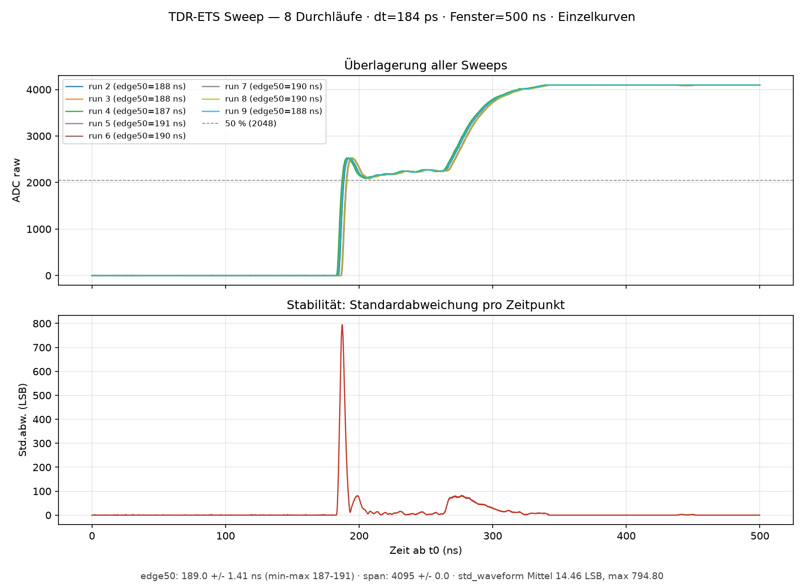
TDR-ETS Sweep Messkurven und Standardabweichung
2 (edge50=188 ns) run 3 (edge50=188 ns) run 4 (edge50=187 ns) run 5 (edge50=191 ns) run 6 (edge50=190 ns) run 7 (edge50=190 ns) run 8 (edge50=190 ns) run 9 (edge50=188 ns) 50 % (2048) ADC raw Überlagerung aller Sweeps Stabilität: Standardabweichung pro Zeitpunkt Std.abw. (LSB) Zeit ab t0 (ns) edge50=189.0 +/- 1.41 ns (min-max 187-191) · span= 4095 +/- 0.0 · std_waveform 14.46 LSB, max 794.80
in „Auflösung der Abtastung eines periodischen Signals mit ADC“ · Mikrocontroller und Digitale Elektronik · · Oszi-Bilder
-
PDF
MCR72.PDF
DEFINES A ZONE WHERE ALL T BODY AND LEAD IRREGULARITIES ARE S ALLOWED. INCHES MILLIMETERS 4 DIM MIN MAX MIN MAX Q A A 0.570 0.620 14.48 15.75 B 0.380 0.405 9.66 10.28 1 2 3 C 0.160 0.190 4.07 4.82 U D 0.025 0.035 0.64 0.88 H F 0.142 0.147 3.61 3.73 G 0.095 0.105 2.42 2.66 K H 0.110 0.155 2.80 3.93 Z J
in „500x Thyristor MCR72-8 ON Semiconductor 600V 8A TO-220AB zu verkaufen“ · Markt ·
-
PDF
ts11.pdf
angle • 4.3~15.3 mm actuator • through hole SPECIFICATIONS parameter conditions/description min typ max units rated voltage 1 12 Vdc rated current 0.01 50 mA withstanding voltage for 1 minute 250 Vac contact resistance applying load of 2 times operating force at 5 Vdc, 10 mA 100 mΩ insulation resistance
-
PDF
LM317.PDF
Regulation and I Adj/Line Test Circuit http://onsemi.com 3 LM317 VI Vin Vout LM317 IL VO(min Load) RL V (max Load) (max Load) O Adjust 240 R R1 1% * L + (min Load) C in 0.1 F Adj CO 1.0 F *▯Pulse testing required. R2 *▯1% Duty Cycle is suggested. 1% VO (min Load)- O (max Load) Load Regulation (mV) =OV (min
in „Spannungsregler für Kleinverbraucher bei 1,2V gesucht“ · Analoge Elektronik und Schaltungstechnik ·
-
PDF
Bereitstellungsunterlagen_EGS_AP2.pdf
16 2 „Jumper“ Steckverbindung, 2-polig RM2,54 Buchsenkontakt 17 1 -A1.K1 IC, 8-Digit-Treiber, THT; MAX7219CNG oder DIP24 inklusive 24-poligem IC-Sockel technisch vergleichbar 1 -A1.K1 IC, 8-Digit-Treiber, SMD MAX7219CWG oder SOIC24 (alternativ) technisch vergleichbar 18 1 -A1.K4 IC, Komparator LM2903N
in „Lochraster-Teil der AP2 Winter 25/26“ · Analoge Elektronik und Schaltungstechnik ·
-
PDF
LITTELFUSE_TVS_DIODE_1_5KE_DATASHEET.pdf
Lead–free assembly p P -Temperature Min (T s(min) 150°C Ramp-up Critical Zone TLtoPT Pre Heat -Temperature Max (T s(max) 200°C L tL T -Time (min to max) (s ) 60 – 180 secs es(max) t Average ramp up rate (LiquidusTemp (T )A e Ramp-down 3°C/second max ps(min) to peak e Preheat T T S(max)T A Ramp-up Rate 3°C/second
in „230V Schutz mit TVS Diode, Auswahl Diode“ · Analoge Elektronik und Schaltungstechnik ·
-
PDF
TDA1591.pdf
kHz; note 3 70 − − dB (SCA) α114 Adjacent Channel Interference (ACI) f = 114 kHz; note 4 − 80 − dB α190 f = 190 kHz; note 4 − 70 − dB PSRR power supply ripple rejection f = 100 Hz; − 35 − dB V = 100 mV ripple(rms) VCO (pin 2) osc oscillator frequency (ceramic resonator) − 456 − kHz frequency range of
in „TDA 7313 input AM / FM“ · Analoge Elektronik und Schaltungstechnik ·
-
PDF
TMT182.pdf
Verwendung) SFF > 73 % PFD 2) 4,69x10⁻⁴ AVG MTBF 3) 263 Jahre Sicherheitsfunktion4) Überwachung min max Bereich λ 26 FIT 101 FIT 117 FIT sd λ 165 FIT 165 FIT 165 FIT su λ dd 108 FIT 33 FIT 17 FIT λ du 107 FIT 107 FIT 107 FIT 1gemäss Kapitel 11.4.4 der IEC 61511-1 2der Wert ist nach ISA S84.01 und IEC
-
Datei
index.html
],[18,176,210,48,190],[20,182,212,48,190],[3,211,49,211,53,219],[3,165,3,161,3,219],[2,133,221],[3,165,3,161,3,227,65,227,69,235],[4,177,228,4,228,19,211,212,19,148,178,212,34,196,34,194,196,34,164,194,49,188],[2,181,226,2,226,18,180,210,211,18,147,211,34,196,34,164,194,196,36,196,50,189
in „KE5FX-Tools unter Linux / Ubuntu / Wine klemmen nach OS-Update“ · PC Hard- und Software ·
-
 Bild
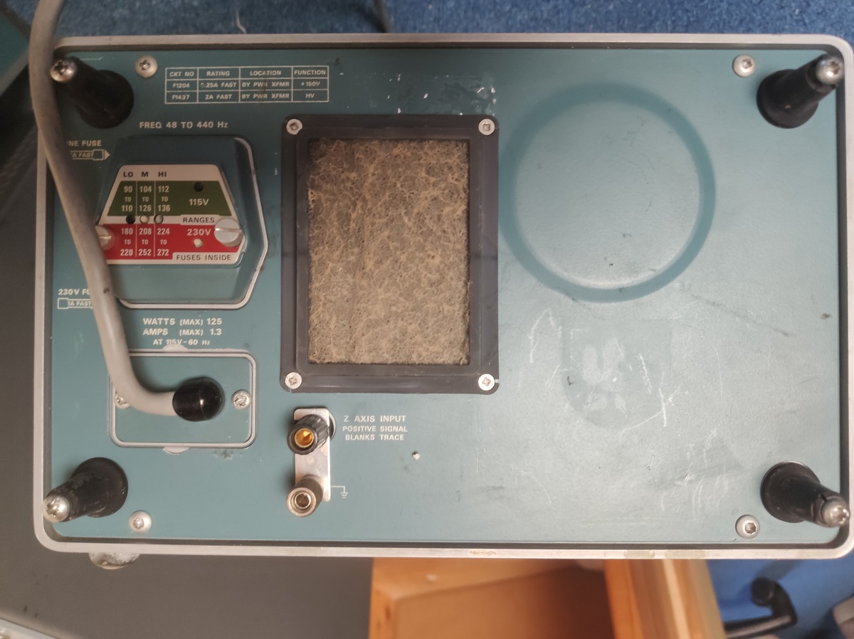
Rückseite eines Messgeräts mit Anschlüssen und Beschriftung
2A FAST PW8 XFMR HV FREQ 48 TO 440 Hz LO MI HI 90 104 112 110 128 136 115V 230V RANGES 180 208 224 190 252 272 FUSES INSIDE 230V FU FAST WATTS (MAX) 125 AMPS (MAX) 1.3 AT 115V-60 Hz Z AXIS INPUT POSITIVE SIGNAL BLANKS TRACE
in „Biete Verschiedene elektronische Messgeräte HP Tektronix Schomandl WaveteK Empire“ · Markt · · Fotos
-
PDF
150rmi.pdf
20 % R Rated RMS ripple current at 100 kHz, 105 °C Nominal case size: Ø 10 mm x 12 mm; Form TFA IL2 Max. leakage current after 2 minRat U tan δ Max. dissipation factor at 100 Hz Ordering code: MAL215035471E3 Former 12NC: 2222 150 35471 Z Max. impedance at 100 kHz Note • Unless otherwise specified, all
in „Ersatz für Kondensator im Schaltnetzteil“ · Analoge Elektronik und Schaltungstechnik ·
-
Datei
SL12NTCs.txt
PART NUMBER RESISTANCE AT 25 °C (R25) TOLERANCE ON R25 VALUE MAX. STEADY-STATE CURRENT UP TO 65 °C MAX. RECOMMENDED ENERGY RATING MAX. VOLTAGE MAX. CAPACITANCE AT 120 V AC RESISTANCE AT 100 % MAX. CURRENT RESISTANCE AT 50 % MAX. CURRENT BODY TEMP. AT 100 % MAX. CURRENT
in „[VS] verschenke 500 Stück NTC Einschaltstrombegrenzer mit ca.14,5 Ohm bei Raumtemperatur“ · Markt ·
-
PDF
Unidrive_SP_Manual.pdf
e 7.5 2128.5 i200-240 Vac Normal Duty Heavy Duty NT-207 S +/- 10% 3Ø NT-212 12.5 37.5 e(kW@220 V, Max Motor Typical Max Motor Typical NT-320 20 569 r HP@230 V) Continuous Power Output Continuous Power Output F Order Code Current (A) (HP) (kW) Current (A) (HP) (kW) 1 10 100 ContinuousStall(lb-inPeak
in „[V Verkaufe Umrichter Emerson Unidrive SP1403“ · Markt ·
-
PDF
TOFC100-xx.pdf
TOSLINK.The other is the TOSLINK 190 Series, ) m—12 which is part of the new generation.The main technical features of (—14 e—16 modules for general-purpose use in the TOSLINK 190 Series are as w l—18 PMAX follows: c—20 PMAX p—22 Data
in „TosLink als einfacher Datenlink“ · Mikrocontroller und Digitale Elektronik ·
-
PDF
20240122_Waasner_Katalog.pdf
aus der nachstehenden For details please refer to the following checklist: Bandbreite: min. 10 mm max. 400 mm Strip width: min. 10 mm max. 400 mm Checkliste: Streifenlänge: min. 20 mm max. 3000 mm Strip length: min. 20 mm max. 3000 mm Lochdurchmesser min. 4,5 max. 28 mm Hole diameter: min. 4.5 mm max. 28 mm Bandbreite: min. 10 mm max. 400 mm Strip width: min. 10 mm max. 400 mm AnzahStreifenlänge: enen Lmin. 20 mm ser: max. 3000 mmmax. 3 NumbStrip length: t diamemin. 20 mm max. 3000 mm max. 3 Materialstärke 0,27 / 0,30 / 0,35 / 0,50
in „Was ist aus dem Transduktor geworden?“ · Analoge Elektronik und Schaltungstechnik ·
-
PDF
Ferrite.pdf
tuning core as they does not implement core tuning. cod. SBK-50 useful space for the coil = 5,2 mm , max 10 turns , max wire Ø 0,3 mm, max inductance ~ 500 nH useful space for the coil = 5,7 mm , max 4,5 turns , cod. SBK-51 max wire Ø 0,6 mm, max inductance ~ 100 nH useful space price 0,45 € -- 0,40 €
in „Gefunden und für gut befunden.Filterliste.“ · HF, Funk und Felder ·
-
PDF
XL4015-DC-DC-Module-Datasheet.pdf
A Max. Duty Cycle D MAX V FBV 100 % VFB0V, Vin=12V, moh Output Power PMOS Rdson SW=5A 60 80 m Rev 1.5 www.xlsemi.com 5 Datasheet 5A 180KHz 36V Buck DC to DC Converter XL4015 Typical SystemApplication (VOUT
in „PCB Schaltplan“ · Mikrocontroller und Digitale Elektronik ·
-
PDF
HD66766R.PDF
189 COM88 9155 653 269 SEG362 6232 1145 349 SEG282 3192 1145 30 C21- -5576 -1168 110 VSH 4911 -1168 190 COM90 9155 691 270 SEG361 6194 1145 350 SEG281 3154 1145 31 C21- -5476 -1168 111 VSH 5011 -1168 191 COM92 9155 729 271 SEG360 6156 1145 351 SEG280 3116 1145 32 VCI2 -5376 -1168 112 VSH 5111 -1168 192
in „LCD-Modul F51661GNCJU-MLW-AA * Info *“ · Mikrocontroller und Digitale Elektronik ·
-
PDF
panasonic-126584-BK-3MCCF.pdf
Japan Capacity 1) Minimum 1900mAh 14.35 mm Nominal Voltage 1.2V Charging Current x Time Fast Charge 2) Max.1900mA Charge Fast Charge 2) 0°C - 40°C Condition Discharge Condition -20°C - 50°C 50.4 mm Ambient Temp. Less than Storage 90days -20°C - 40°C Condition Less than -20°C - 30°C 1year Internal Impedance
in „Batteriefach zum Einbau in Gehäuse mit Deckel“ · Mechanik, Gehäuse, Werkzeug ·
-
PDF
LF-SMCJ.pdf
assembly T p P -Temperature Min (Ts(min) 150°C Ramp-up Critical Zone TLtoPT Pre Heat -Temperature Max (T s(max) 200°C ) TL L -Time (min to max) (t) 60 – 180 secs ( s rs(max) Average ramp up rate (LiquidusTemp (T ) a A 3°C/second max eT Ramp-down to peak ms(min) t T Preheat T S(max)T A Ramp-up Rate 3°C/second max Reflow -Temperature (TA) (Liquidus) 217°C 25˚C -Time (min to max) (t) 60 – 150 seconds t 25˚C to Peak s Time (t) PeakTemperature (T P) 260+0/-°C Time within 5°C of actual peak 20 – 40 seconds Temperature
in „Welches Bauteil ist das?“ · Analoge Elektronik und Schaltungstechnik ·
-
Datei
st96_messinstrument_e.html
>0.0</span> A</div> <div class="row"> <label>0</label> <input type="range" id="rangeInput" min="0" max="60" step="0.1" value="0"> <label>60</label> </div> <div class="row" style="justify-content:center;"> <label for="numberInput">Zeigerwert:</label> <input type="number" id="numberInput" min="0" max="
in „Suche Grafiker-Hilfe: analoge Messinstrumente nachbilden“ · Softwareentwicklung ·
-
PDF
Motorola_MC44353_MC44354_MC44355_1998.pdf
Programmable 1 0 1 240 mVrms 230 mVrms Not Programmable 1 1 0 215 mVrms 205 mVrms Not Programmable 1 1 1 190 mVrms 185 mVrms 190 mVrms NOTE: 1.Audio sensitivity bits AMD2–0 are located in C1 bits 6 to 4. Table 5. Picture to Sound Carrier Ratio (Control Bits) P/S Carrier Ratio P/S Carrier Ratio PSD2 PSD1 PSD0
in „Pollin ist pleite :-(“ · Offtopic ·
-
PDF
NTCLE100E-SERIES_ENG_TDS.pdf
H2 I H 1 L 0 - 40 0 55 85 125 150 P d Tamb(°C) Note • Zero power is considered as measuring power max. 1 % of max. power. PHYSICAL DIMENSIONS FOR RELEVANT TYPE (all dimensions in millimeters) H1 R25VALUE BMAX. d H2 MAX. L P T MAX. MIN. MAX. 3.3 to 220 5.0 0.6 ± 0.06 1.0 4.0 6.0 24 ± 1.5 2.54 4.0
in „Gaggenau Backofen NTC-Luftfühler defekt“ · Haus & Smart Home ·
-
PDF
NTCLE100E-SERIES_ENG_TDS.pdf
H2 I H 1 L 0 - 40 0 55 85 125 150 P d Tamb(°C) Note • Zero power is considered as measuring power max. 1 % of max. power. PHYSICAL DIMENSIONS FOR RELEVANT TYPE (all dimensions in millimeters) H1 R25VALUE BMAX. d H2 MAX. L P T MAX. MIN. MAX. 3.3 to 220 5.0 0.6 ± 0.06 1.0 4.0 6.0 24 ± 1.5 2.54 4.0
in „Defekt bei Sentiotec Sauna/Infrarotkabinen-Steuerung“ · Haus & Smart Home ·
-
Datei
esp_Gleissteuerung_OK.ino
:flex;justify-content:space-between; align-items:center;gap:8px;flex-wrap:wrap } main{padding:10px;max-width:1100px;margin:auto} .panel{ background:#1d2935;padding:12px; margin:10px 0;border-radius:10px } button{ padding:10px 12px;margin:4px; border:2px solid #536575;border-radius:7px; background:#304253
-
PDF
6020-1102-01_RevF_MCA1101_20210408.pdf
1.3 0.3 1.3 % Total Error Drift E (Note 6) -1.7 ±0.4 1.7 %FS TOT(D) Note 4: Typ values are 1. Min/max values are guaranteed by production test Note 5: Guaranteed by design and characterization. Typ values are 1, min/max values are 3. Note 6: Worst case numbers are based on 3 lots qualification data
in „High Side Strommessung“ · Analoge Elektronik und Schaltungstechnik ·
-
PDF
MAX971-MAX984.pdf
1/MAX9_2/MAX9_3) 9 devices draw less than 4µA supply current over Ultra-Low Quiescent Current (4µA, max) 7 temperature (MAX971/MAX972/MAX981/MAX982), and Over Extended Temp Range (MAX971/MAX981) 1 include
in „Komparator Aufbau - diskret oder über µC?“ · Mikrocontroller und Digitale Elektronik ·
-
Datei
ESP_Gleissteuerung_29_10_26_A_WS_2.ino
:flex;justify-content:space-between; align-items:center;gap:8px;flex-wrap:wrap } main{padding:10px;max-width:1100px;margin:auto} .panel{ background:#1d2935;padding:12px; margin:10px 0;border-radius:10px } button{ padding:10px 12px;margin:4px; border:2px solid #536575;border-radius:7px; background:#304253
-
PDF
BZY97Cxx.pdf
Number code V ZI ZT f=1kH @I ZT IZT R V R @T =60°C Z amb tp=10ms V V Ω Αvz(10 /K) m A µ A V m A A Min. Max. typ BZY97C3V9 Y3V9 3.7 4.1 7.0 -0.025 100 15 1.0 366 3.7 BZY97C4V3 Y4V3 4.0 4.6 7.0 -0.020 100 10 1.0 327 3.4 BZY97C4V7 Y4V7 4.4 5.0 7.0 -0.020 100 5.0 1.0 300 3.1 BZY97C5V1 Y5V1 4.8 5.4 5.0 -0.010
in „[VS] Trafo Block 2*12V 30VA, Z-Diode 10V, kleines Netzteil 12V“ · Markt ·
-
PDF
ch9121.pdf
maximum value may cause the chip to work abnormally or even be damaged. Name Parameter description Min. Max. Unit VCC33=3.3V TA Ambient temperature during operation -40 85 ℃ VCC18=1.8V CH9121 Datasheet 5 TS Ambient temperature during storage -55 125 ℃ VCC33 Supply voltage (VCC33 connects to power, GND to
in „Serieller Tunnel durch IP-Netz?“ · Mikrocontroller und Digitale Elektronik ·
-
PDF
1540fb.pdf
Source Current pin. Each comparator’s input operates from the negative n Pin Compatible with LTC1440, MAX921, MAX931 supplytowithin1.3Vofthepositivesupply.Thecompara - toroutputstagecancontinuouslysourceupto40mA.By APPLICATIONS eliminating the cross-conducting current that normally occur when the comparator
in „Komparator Aufbau - diskret oder über µC?“ · Mikrocontroller und Digitale Elektronik ·
-
PDF
Stenorette_2010_SW.pdf
Kopfspiegef an der Lehre anliegt, dund sor dern- gentstärkeregfer an Kgemessen. (Steckerleiste) ge- max. Abstand von 0,1 mm eingehalten uird. lvlassnach lvlS1 Uiedergabe-Pegelkontrolle bei geschlossenem Deckel uiederho.Ien. b) Kopfhöhe Der AIJL-Kopf uird mit der gleichen Lehre so ein- gestellt, daß die
in „Recht auf Reparatur“ · Offtopic ·
-
PDF
WIMA_DC_Link_MKP_4.pdf
Führungslöcher W 1 9,0± 0, 9,0± 0, 9,0± 0, 9,0± 0, 9,0± 0,5 9,0± 0,5 9,0± 0,5 Lage Klebeband W 0,5bis 3,0max, 0,5bis 3,0max, 0,5bis 3,0max, 0,5bis 3,0max, 0,5bis 3,0max, 0,5bis 3,0max, 0,5bis 3,0max, 2 Führungsloch-Durchmesser D 4,0± 0, 4,0± 0, 4,0± 0, 4,0± 0, 4,0± 0,2 4,0± 0,2 4,0± 0,2 0 Abstandder Bauelemente
-
Datei
fritzbox_7590_log.txt
: 1000000000Hz mips_hpt_frequency 500000000Hz [ 0.000000][ T0] clocksource: gptc: mask: 0xffffffff max_cycles: 0xffffffff, max_idle_ns: 9556302233 ns [ 0.010146][ T0] Calibrating delay loop... 718.84 BogoMIPS (lpj=1437696) [ 0.046807][ T0] pid_max: default: 32768 minimum: 301 [ 0.052302][ T0] Security
in „FritzBox 7590 Boot Loop“ · Mikrocontroller und Digitale Elektronik ·
-
PDF
217369.pdf
, y a PARTNUMBER/STANDARDCONFIGURATIONS W a Numberof “A” “B” “C” y (10,16) “A” PartNumber Contacts Max. Max. Max. R Max. Max. 1.100 .900 .700 3 514-AG21D 14 (27,49) (22,86) (17,78) 2 . 1.220 1.010 .800 n “C” (2,54) “B” 516-AG21D 16 (30,99) (25,65) (20,32) , Max. Typ. Max. g r e i Note: Before ordering
in „Kühlkörper TO3 Befestigungslöcher zu groß?“ · Mechanik, Gehäuse, Werkzeug ·
-
PDF
C462925.pdf
2) Lead Temperature Soldering T °C SLD Reflow (SMD styles only), Leaded, 60−150 s above 183, 30 s max at peak − 240 Reflow (SMD styles only), Lead Free, 60−150 s above 217, 40 s max at peak − 265 Wave Solder (through hole styles only), 12 sec max − 310 2. Per IPC/JEDEC J−STD−020C. Table 4. THERMAL CHARACTERISTICS
in „Verpolungsschutz“ · Analoge Elektronik und Schaltungstechnik ·
-
PDF
lnix-s-a0001298418-1.pdf
: 1994 + A1:2001 EN 61000-4-11: 2004 Recommended Operating Conditions Parameter Symbol Min Typical Max Units Supply Voltage VCC 3.14 3.3 3.46 Vdc Supply Voltage Ripples VCC PP 2.0 % Power Reset Threshold 2.7 Vdc RESET Pin Input Low Voltage VRES IL 0.36 Vdc RESET Pin Input High Voltage V 2.0 3.46 Vdc
in „[V] 1Stück gebrauchtes XPORT-EDGE_Seriell- LAN Modul (12€)“ · Markt ·
-
PDF
lnix-s-a0001298418-1.pdf
: 1994 + A1:2001 EN 61000-4-11: 2004 Recommended Operating Conditions Parameter Symbol Min Typical Max Units Supply Voltage VCC 3.14 3.3 3.46 Vdc Supply Voltage Ripples VCC PP 2.0 % Power Reset Threshold 2.7 Vdc RESET Pin Input Low Voltage VRES IL 0.36 Vdc RESET Pin Input High Voltage V 2.0 3.46 Vdc
in „[V] 1Stück neues Lantronix_XPORT_Seriell- LAN Modul (18€)“ · Markt ·
-
Datei
sanduhr_1.html
letter-spacing: .22em; text-transform: uppercase; color: #c9a86a; } canvas { display: block; width: 100%; max-width: 430px; height: auto; touch-action: manipulation; } .hud { display: flex; gap: 28px; font-variant-numeric: tabular-nums; font-size: 14px; letter-spacing: .06em; } .hud div { color: #9c8664; }
-
PDF
swissbit-U500-USB3-Stick.pdf
I_IDL 30 40 Suspend current I_CCS 1.6 2.5 Write current I_WR 180 200 Read current I_RD V_Bus=5.0V 190 210 Idle current I_IDL 8/16/32GB (BGA) 406 50 Suspend current I_CCS 2 2.5 Table 15: DC characteristics for High-Speed operation (T=25°C, V_Bus=5V or 3.3V) Parameter Symbol Test condition Min Typ Max
in „[S] USB Stick für Produktdoku - weniger Speicher, mehr Zuverlässigkeit“ · Markt ·
-
PDF
40146F.pdf
0°C to +70°C Industrial(I):Tamb = -40°C to BSEL = 0 BSEL = 1 +85°C Symbol Characteristic Min Typ. Max. Min. Typ. Max. Units TE Basic pulse element 260 400 620 130 200 310 μs TBP PWM bit pulse width 3 3 TE TP Preamble duration 28 28 TE TS Sync Pulse duration 10 10 TE TH Header duration 10 10 TE THOP
in „Fehlersuche Funksender Zentralverriegelung Toyota Yaris“ · Fahrzeugelektronik ·
-
PDF
TM56E6422-tenxtechnology.pdf
pending flag This bit is set by H/W while EEPROM is written, write 0 to this bit will clear this flag 190h Bit 7 Bit 6 Bit 5 Bit 4 Bit 3 Bit 2 Bit 1 Bit 0 EEPCTL EEPTO – – – – – EEPTE R/W R – – – – – R/W Reset 0 – – – – – 0 0 190h.7 EEPTO: EEPROM write time-out flag DS-TM56E6422_E 17 Rev 0.9, 2024/04/10
in „MCU identifikation/Datenblatt - MC9989A0ZQ“ · Mikrocontroller und Digitale Elektronik ·
-
Datei
Lambdacontroller_ai_claude_2.ino
int serial_counter = 0; uint16_t CJ125_Status = 0; // PID int dState = 0; int iState = 0; const int iMax = 250; const int iMin = -250; const float pGain = 120.0; const float iGain = 0.8; const float dGain = 10.0; // ----------------------------- // Lambda- und O2-Tabellen (Platzhalter) // -------------
in „Bosch CJ125 mit AVR AT90CAN64“ · Mikrocontroller und Digitale Elektronik ·
-
Datei
Lambdacontroller_ai_claude.txt
int serial_counter = 0; uint16_t CJ125_Status = 0; // PID int dState = 0; int iState = 0; const int iMax = 250; const int iMin = -250; const float pGain = 120.0; const float iGain = 0.8; const float dGain = 10.0; // ----------------------------- // Lambda- und O2-Tabellen (Platzhalter) // -------------
in „Bosch CJ125 mit AVR AT90CAN64“ · Mikrocontroller und Digitale Elektronik ·
-
PDF
TJA1020.pdf
proof to battery and ground • Thermally protected. QUICK REFERENCE DATA SYMBOL PARAMETER MIN. TYP. MAX. UNIT VBAT supply voltage on pin BAT 5 12 27 V BAT supply current on pin BAT in sleep mode 1 3 8 A supply current on pin BAT in standby mode; bus recessive 100 400 1000 A supply current on pin BAT in
in „[S] MCP2004 LIN Tranceiver oder andere gesucht“ · Markt ·
-
PDF
T6963C.pdf
character generator ROM (code 0101) T6963C−0101 is built in as standard. ▯External display memory : 64 KB Max The addresses in display memory of the text area, graphic area and external character generator area are determined by software. ▯Read or Write operations from the CPU do not disturb the display. ▯A
in „altes Phytec MCB-51 Monitor/Basic Befehle?“ · Mikrocontroller und Digitale Elektronik ·
-
PDF
infineon-ug-202311-pl52-2312-121012-solid-state-circuit-breaker-reference-design-user-guide-usermanual-en.pdf
Solid-state circuitbreakerreferencedesignuserguide SSCBdevices ata glance Table3 Parameter Parameter Min Typ Max Unit Absolutemaximumchannelsupplyrange 90 – 260 VAC 120 – 375 VDC Operatingchannelsupplyrange 100 – 240 VAC 330 – 370 VDC NominalcurrentatTa=25°C – 16 – A StaticoverdrivefactoratTa=25°C – – 1.13 – I
in „Leitungsschutzschalter 24VAC“ · Analoge Elektronik und Schaltungstechnik ·
-
PDF
Induktionsherde_Serviceanleitung.pdf
- 9 Cooking sensor programs min-med-max) Residual heat indicator H/h 9 Frying sensor programs Residual heat indicator H/h Power management Power management Child lock Child lock Key lock Key lock r630005d - 16.10.2008 – Dieter Helmich Page
in „Serviceanleitung Induktionsherde Bosch, Siemens, Neff u.a“ · Haus & Smart Home ·
-
PDF
rd70hvf1c.pdf
CHARACTERISTICS (Tc=25°C , UNLESS OTHERWISE NOTED) LIMITS UNIT SYMBOL PARAMETER CONDITIONS MIN TYP MAX. DSS Zero gate voltage drain current Vds=17VGS=0V - - 300 uA GSS Gate to source leak current Vgs=10V, V DS=0V - - 5 uA VTH Gate threshold voltage Vds=12V, IDS=1mA 1.6 2.0 2.4 V Pout Output power f=175MHz
in „HF Transistoren“ · Analoge Elektronik und Schaltungstechnik ·
-
PDF
edip128-6e.pdf
Codes Remarks reset Call macros Run normal macro N n1 Call the (normal) macro with the number n1 (max. 7 levels) Run touch macro T n1 Call the touch macro with the number n1 (max. 7 levels) Run menu macro ESC M M n1 Call the menu macro with the number n1 (max. 7 levels) Run port macro P n1 Call the port macro with the number n1 (max. 7 levels) Run bit macro B n1 Call the bit macro with the number n1 (max. 7 levels) automatic (normal-) macros Call the (normal) macro with the number n1 in n2/10s. Execution is stopped by commands