-
PDF
Hameg_Bourns_Ersatz.pdf
.063) OR C 1.0 OR C (.039) (.039) L1 LB L2 L3 L1 LB L2 L1 LB L2 15 5 7 9 9.5 5 2.9 9.5 5 3 (.591) (.197) (.276) (.354) (.374) (.197) (.114) (.374) (.197) (.118) 20 7 9 10 13.5 5 6.9 15 5 7 (.787) (.276) (.354) (.394) (.531) (.197) (.272) (.591) (.197) (.276) 20 7 10 (.787) (.276) (.394) PEC11S with 1.5
-
PDF
Operationsverstaerker_Auswahl.pdf
Geeignete bzw. passende Typen wären beispielsweise: MCP6022 (Rail-to-Rail, 2,8 MHz, 7 V/µs, allerdings max. 6 V Versorgung → nicht geeignet für ±15 V) OPA197 – passt sehr gut: Versorgung: ±2,25 V bis ±18 V Rail-to-Rail-Ausgang GBW: 10 MHz Slew Rate: 20 V/µs OPA192 Versorgung bis ±18 V Rail-to-Rail Ein- und
in „Suchmaschine für Halbleiter gesucht“ · Analoge Elektronik und Schaltungstechnik ·
-
PDF
TOFC100-xx.pdf
devices. Dynamicrangeofdevicesforgeneral-purposeuse Application circuits Application circuits for theTOTX197 andTORX196, a pair of transmission and receiving modules for general-purpose use, are shown in the figure on the insertionsideonnector insertionsideonnector right.For theTOTX197 transmission module,
in „TosLink als einfacher Datenlink“ · Mikrocontroller und Digitale Elektronik ·
-
 Bild
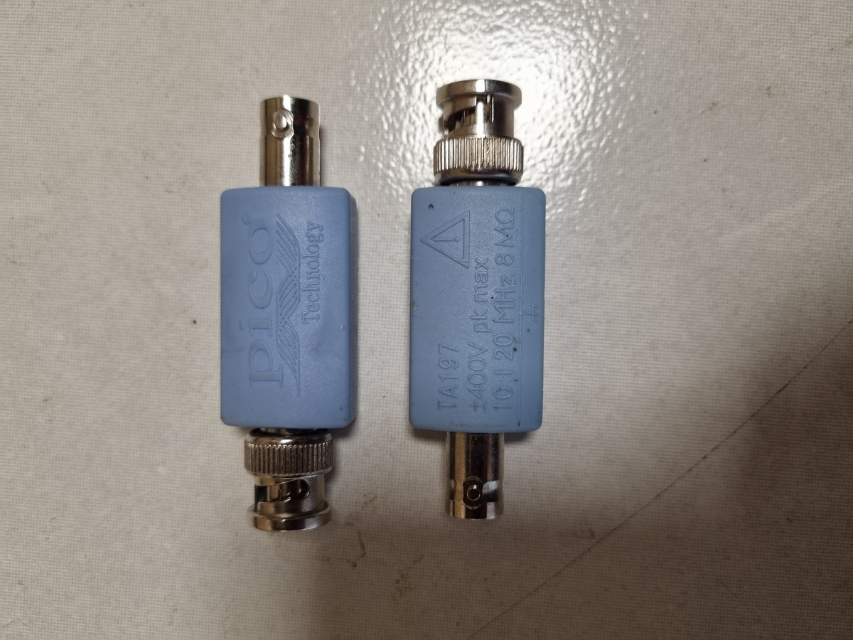
Zwei Pico Technology BNC-Adapter
pico Technology TA197 ±400V pk max 10-120 MHz 8 MΩ
in „[V] Tastkopfset und Teiler“ · Markt · · Fotos
-
PDF
1540fb.pdf
Source Current pin. Each comparator’s input operates from the negative n Pin Compatible with LTC1440, MAX921, MAX931 supplytowithin1.3Vofthepositivesupply.Thecompara - toroutputstagecancontinuouslysourceupto40mA.By APPLICATIONS eliminating the cross-conducting current that normally occur when the comparator
in „Komparator Aufbau - diskret oder über µC?“ · Mikrocontroller und Digitale Elektronik ·
-
 Bild
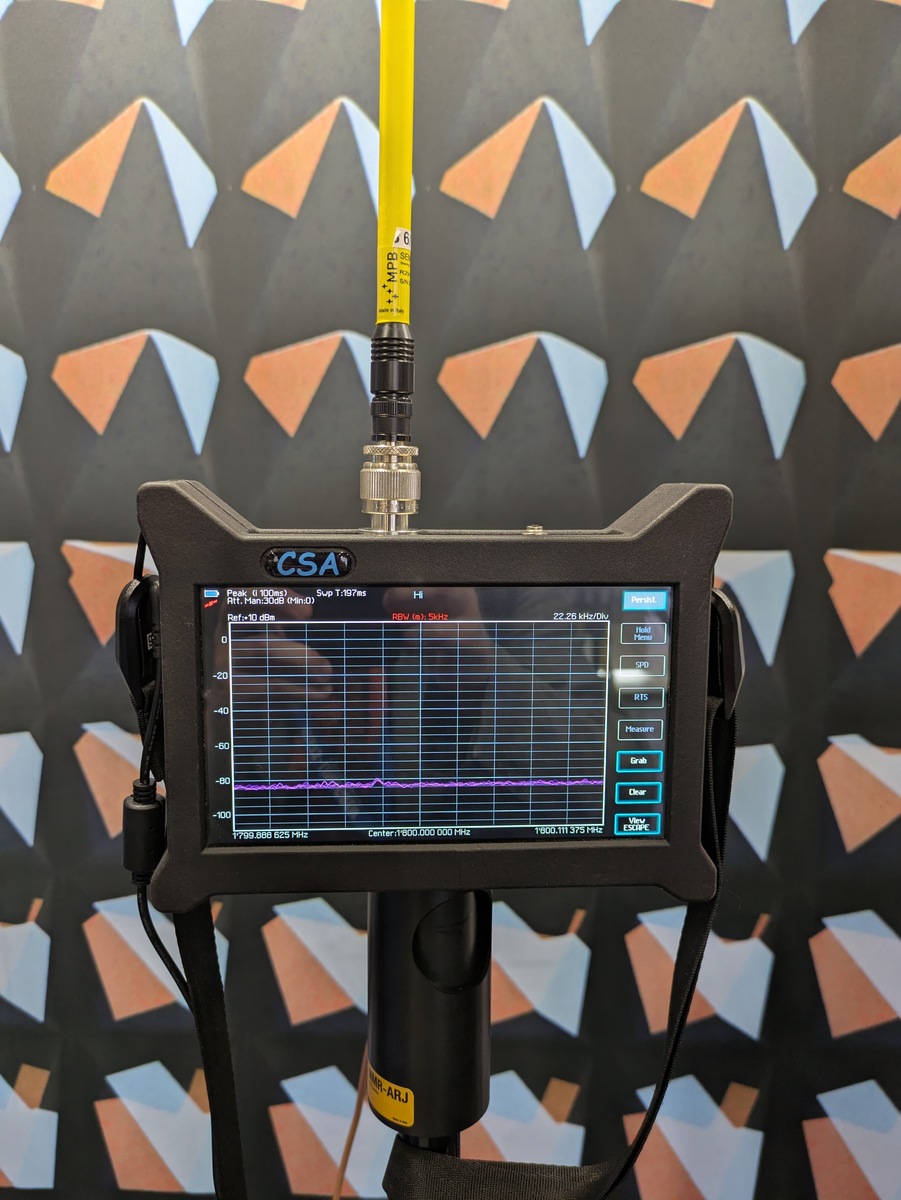
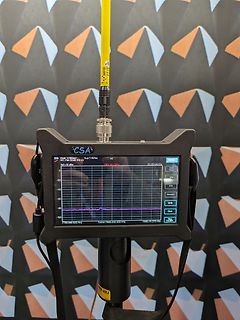
Spektrumanalysator mit Messkurve und Antenne
CSA Peak: 0 dBm Avg: T/197 ms Ref: Max 30 dBm RBW: 1 Hz Span: 22.26 kHz/Div 0 -20 -40 -60 -80 -100 1799.000 GHz 1800.000 MHz 1801.111 GHz Hold Menu SPD RTS Moment Grab Clear View ESCAPE
in „EMV 2026 – FFT-Spektralanalysatoren, Dosimeter für EMV, Optisches und mehr“ · Mikrocontroller und Digitale Elektronik · · Fotos
-
 Bild
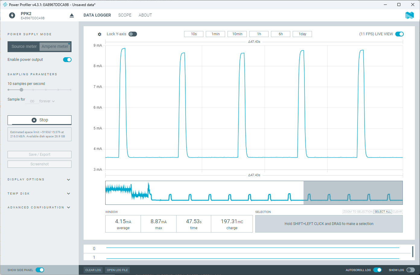
Screenshot eines Stromverbrauch-Messprotokolls
DISK ADVANCED CONFIGURATION WINDOW SELECTION ZOOM TO SELECTION SELECT ALL CLEAR 4.15mA average 8.87mA max 47.53s time 197.31mC charge Hold SHIFT+LEFT CLICK and DRAG to make a selection SHOW SIDE PANEL CLEAR LOG OPEN LOG FILE AUTOSCROLL LOG SHOW LOG
in „simcom sim7022 will nich einschlafen“ · Mikrocontroller und Digitale Elektronik · · Screenshots

-
PDF
Inverse_voltage-MC34063ACD-STMicroelectronics.pdf
---------------------- --------------- V IN(min)– Vsat V IN(min)– Vsat – VOUT V IN – Vsat (t + t ) max 1/f 1/f 1/f on off min min min C 4.5x10 t5 4.5x10 t5 4.5x10 t5 T on on on I 2I [(t /t )+1] 2I 2I [(t /t )+1] PK(switch) out(max) on off out(max) out(max) on off R 0.3/I 0.3/I 0.3/I SC PK(switch) PK(
in „Ein passender Widerstand für MC34063“ · Analoge Elektronik und Schaltungstechnik ·
-
PDF
MAX971-MAX984.pdf
1/MAX9_2/MAX9_3) 9 devices draw less than 4µA supply current over Ultra-Low Quiescent Current (4µA, max) 7 temperature (MAX971/MAX972/MAX981/MAX982), and Over Extended Temp Range (MAX971/MAX981) 1 include
in „Komparator Aufbau - diskret oder über µC?“ · Mikrocontroller und Digitale Elektronik ·
-
PDF
HD66766R.PDF
256 SEG375 6726 1145 336 SEG295 3686 1145 17 C24+ -6957 -1168 97 DUMMY8 3530 -1168 177 COM64 9155 197 257 SEG374 6688 1145 337 SEG294 3648 1145 18 C24- -6857 -1168 98 DUMMY9 3630 -1168 178 COM66 9155 235 258 SEG373 6650 1145 338 SEG293 3610 1145 19 C24- -6757 -1168 99 VREFL 3810 -1168 179 COM68 9155
in „LCD-Modul F51661GNCJU-MLW-AA * Info *“ · Mikrocontroller und Digitale Elektronik ·
-
PDF
SAA7220.PDF
, SAA7220 and 16-bit dual DAC (TOA1541) QUICK REFERENCE DATA parameter conditions symbol min. typo max. unit 4,5 5,0 5,5 V Supply voltage (pin 24) VOO Supply current (pin 24) 100 100 180 285 rnA Input voltage ranges WSAB,OAAB,EFAB,SOAB note 2 CLAB, SCAB, ATSB, MUSB note 3 Input voltage LOW note 1 VIL
in „Hilfe: Takt Mission (Philips) CD-Player fällt aus“ · Analoge Elektronik und Schaltungstechnik ·
-
PDF
LiIonCharger_BQ2057C_extMOSFETorPNP.pdf
needed in order to keep the junction temperature below the manufacturer’s recommended value, T (J)max Calculate the total theta, θ(°C/W), needed. (T - T ) q JC= (J)max A(max) PD (150 40 ) q JC= 1.4 q JC= 78 ° / W (8) Now choose a device package with a theta at least 10% below this value to account for
in „LiIon Charger BQ2057 - wozu dieser Widerstand?“ · Analoge Elektronik und Schaltungstechnik ·
-
PDF
RBS17707-SN65HVD230-CAN-Board-Datasheetsiyyp0AhGRhw5g.pdf
over recommended operating conditions (unless otherwise noted) PARAMETER TEST CONDITIONS MIN TYP † MAX UNIT VIT+ Positive-going input threshold voltage 750 900 mV See Table 1 VIT– Negative-going input threshold voltage 500 650 mV Vhys Hysteresis voltage IT+ – IT–) 100 VOH High-level output voltage –6
in „PCB Schaltplan“ · Mikrocontroller und Digitale Elektronik ·
-
PDF
25040.pdf
packaging E1 D 2 n 1 α E A A2 L c A1 β B1 p eB B Units INCHES* MILLIMETERS Dimension Limits MIN NOM MAX MIN NOM MAX Number of Pins n 8 8 Pitch p .100 2.54 Top to Seating Plane A .140 .155 .170 3.56 3.94 4.32 Molded Package Thickness A2 .115 .130 .145 2.92 3.30 3.68 Base to Seating Plane A1 .015 0.38 Shoulder
in „Eeprom Philip Pines Auslesen mit CH341“ · Fahrzeugelektronik ·
-
Datei
Lambdacontroller_ai_claude_2.ino
int serial_counter = 0; uint16_t CJ125_Status = 0; // PID int dState = 0; int iState = 0; const int iMax = 250; const int iMin = -250; const float pGain = 120.0; const float iGain = 0.8; const float dGain = 10.0; // ----------------------------- // Lambda- und O2-Tabellen (Platzhalter) // -------------
in „Bosch CJ125 mit AVR AT90CAN64“ · Mikrocontroller und Digitale Elektronik ·
-
Datei
Lambdacontroller_ai_claude.txt
int serial_counter = 0; uint16_t CJ125_Status = 0; // PID int dState = 0; int iState = 0; const int iMax = 250; const int iMin = -250; const float pGain = 120.0; const float iGain = 0.8; const float dGain = 10.0; // ----------------------------- // Lambda- und O2-Tabellen (Platzhalter) // -------------
in „Bosch CJ125 mit AVR AT90CAN64“ · Mikrocontroller und Digitale Elektronik ·
-
PDF
T6963C.pdf
character generator ROM (code 0101) T6963C−0101 is built in as standard. ▯External display memory : 64 KB Max The addresses in display memory of the text area, graphic area and external character generator area are determined by software. ▯Read or Write operations from the CPU do not disturb the display. ▯A
in „altes Phytec MCB-51 Monitor/Basic Befehle?“ · Mikrocontroller und Digitale Elektronik ·
-
PDF
217369.pdf
, y a PARTNUMBER/STANDARDCONFIGURATIONS W a Numberof “A” “B” “C” y (10,16) “A” PartNumber Contacts Max. Max. Max. R Max. Max. 1.100 .900 .700 3 514-AG21D 14 (27,49) (22,86) (17,78) 2 . 1.220 1.010 .800 n “C” (2,54) “B” 516-AG21D 16 (30,99) (25,65) (20,32) , Max. Typ. Max. g r e i Note: Before ordering
in „Kühlkörper TO3 Befestigungslöcher zu groß?“ · Mechanik, Gehäuse, Werkzeug ·
-
PDF
Induktionsherde_Serviceanleitung.pdf
- 9 Cooking sensor programs min-med-max) Residual heat indicator H/h 9 Frying sensor programs Residual heat indicator H/h Power management Power management Child lock Child lock Key lock Key lock r630005d - 16.10.2008 – Dieter Helmich Page
in „Serviceanleitung Induktionsherde Bosch, Siemens, Neff u.a“ · Haus & Smart Home ·
-
PDF
Magazin_Bauteile.pdf
Spannungsregler SMD MIC5504-3.3YM5-TR 3,3V 300mA LDO Microchip Farnell 251-0377 0,142 0,43 4 5 5 3 DC-DC Wandler MAX653CPA+ 5V -> 3V 225mA 8-DIP Analog Devices Farnell 279-9237 3,300 9,90 X 4 6 1 4 Mikrocontroller ATMEGA644P-20PU DIP40 Microchip Farnell 145-5122 6,490 25,96 3 Mikrocontroller ATMEGA644P-20PU SMD Microchip Farnell 145-5121 6,230 18,69 2 Mikrocontroller ATMEGA1284-AU SMD Microchip Farnell 197-2064 5,440 10,88 4 6 2 2 I2C Bus Repeater PCA9517ADMR2G Onsemi Farnell 284-5092 0,845 1,69 X 4 6 3 1 2 RS485 LTC490CN8#PBF Analog Devices Farnell 402-4359 9,900 19,80 2 2 RS485 MAX485CSA+ SMD und DIP
-
PDF
Sartorius_Waage_Manual_Anleitung_Handbuch_QC7DCE-S.pdf
/i key + print information: p/p key + Target weight z/T key Set Setp Min weight value S – min Max weight value S + max Tolerance ranges when values entered via keypad: or Delta min d – d min Delta max d + d max Numeric entry: Numeric keys 0–9 Enter parameters and . + z/T key for “Weight” Target
in „Frage zu einer Waage / Sartorius QC7DCE-S“ · Mechanik, Gehäuse, Werkzeug ·
-
PDF
asus-p701-unlocked.pdf
ACOK# 3 1 Vcls=3.413V GND K U 2 2 G1 N D1 7 2 1 1 MAX8724_REF MAX8724_LDO 5 0 2 T PR9 MAX8724_LDO PL1 PR8 /X S G PR12 7 1 S BAT_LX_20mil 3 S2 D2 6 1 2 1 2 BAT 2 PQ7 10KOhm _ 2 1 0 2N7002 GND 1 A 2 4 G2 N D2 5 2 S 6.2UH 2 25mOHM E 5 /X GND B 33Ohm 1 Irat
-
PDF
rpb_verzeichnis_der_700_bauanleitungen_1971.pdf
V : 24 V, 20 W S. 111/112 Dreistufiger Wandler für Mobilsender- Endröhre 11,5...14 V : 225/450 V (max. 120 mA) S.113/119 17 Grid-Dipmeter-+ Dipmeter Hallverstärker (künstl. Nachhall) RPB 7/8 Niederfrequenz-Verstärker mit Röhren und Transistoren, 13. Auflage Mehrere Schaltungsvorschläge S.62/66 RPB 331
in „Welche Bücher sind im "Radio-Praktiker Bücherei E-Book-Bundle 3 - Ton, Musik & Aufnahme"?“ · Offtopic ·
-
PDF
technical.pdf
and V ds being the intrinsic drain-source voltage. The charge and capacitances are: for V > V new max 168 V max Vnew − V max Q gs = Cgs0· 2·Vbi 1 − 1 − + (11.364) V bi 1 − VVax bi ∂Q gs C gs0 ∂Vnew = · (11.365) ∂Vgs 1 − VVax ∂V gs bi ∂Q gs C gs0 ∂Vnew = · (11.366) ∂Vgd 1 − VVax ∂V gd bi and
-
PDF
TM56M152A-tenxtechnology.pdf
relative description 0.85 Oct, 2023 3. delete the description about 1/2 Bias and pull-down 4. Modify Max. value of TotalAccuracy and Integral Non-Linearity of ADC Electrical Characteristics 5.Add SOP-14 and change PA2 as PB0 in MSOP-10 and DFN-10 1. Update Electrical Characteristic 0.86 Oct, 2023 2. Modified
in „MCU identifikation/Datenblatt - MC9989A0ZQ“ · Mikrocontroller und Digitale Elektronik ·
-
PDF
TM56E6422-tenxtechnology.pdf
EV083(1).docx of JHLin 0.84 Aug, 2023 0.85 Aug, 2023 1. Modify the timing diagram of ADC 1. Modify Max. value of Total Accuracy and Integral Non-Linearity of ADC Electrical Characteristics 2. Add the table of “EEPROM Characteristics” 3. Add subsection for the section of “PWM Trigger ADC” 4. Add description
in „MCU identifikation/Datenblatt - MC9989A0ZQ“ · Mikrocontroller und Digitale Elektronik ·
-
Datei
Schrittmotor.asm
(0<<CS32)|(0<<CS31)|(1<<CS30) ;TCCR1B sts TCCR3B, AL ; 16 Bit Counter 1 Mode 4 CTC OCRnA Immediate MAX - Taktgeber ldi AL, (0<<COM1A1)|(0<<COM1A0)|(0<<COM1B1)|(0<<COM1B0)|(0<<WGM11)|(0<<WGM10) ;TCCR1A sts TCCR1A, AL ldi AL, (0<<WGM13)|(1<<WGM12)|(0<<CS12)|(0<<CS11)|(1<<CS10) ;TCCR1B sts TCCR1B, AL ldi
in „Spielerei mit einem 2- und 5-Phasen-Schrittmotor“ · Projekte & Code ·
-
PDF
PMT_handbook_v4E.pdf
measure anode luminous sensitivity) VOLTAGE 0 V ON LIGHT LEVEL OFF 5 6 7 8 9 (minutes) 1 µA ANODE I max. OUTPUT Ii I min. OR Ii I max. I min. 5 6 7 8 9 (minutes) WARM-UP PERIOD (5 minutes or more) THBV4_0440EA Figure 4-40: Light hysteresis In light hysteresis test, the photomultiplier tube is operated
in „Suche nach geeignetem OpAmp als Impedanzwandler“ · Analoge Elektronik und Schaltungstechnik ·
-
PDF
grundig32zollLedTV.pdf
: C0 C743 C733 C734 TP89 470nF VCC3V3_FE 3.3uH C724 VCC3V3_FET 10K*4 35VF 35VF 25V IC703 C723 xxmA max LNBH29EQTR 22uF 100NF 14 13 D702 VUP VOUT 220nF C735 6 50V PMEG4010EH PMEG4010EH 16 LX D703 VCC3V3 EPAD 17 L711 NC 15 R709 SATELLITETUNER L712 6.8uH NC 11 NC 3A 60R 1 12 NC C740 +12V VCC 3 R710 R711 VCC3V3_FES C725 C726 C737 C736 DSQIN/EXTM L709 150mA max 100nF 100nF 10NF 0R 15.4K VCC3V3_FE TP88 VCC3V3_FES 10uF35V R715 8 9 220nF50V 6 SCL BYP 10 4.7K L714 7 u 7 n R706 7 SDA C727 NC C 1 C 1 12 I2CM_SDA 5 ADDR N D C742 I2CM_SCL 8 ISEL P G N SAT1 10UF 7
in „Reparaturbericht LED-TV Grundig 32 VLE 5620 BN Ton gut, aber kein Bild“ · Analoge Elektronik und Schaltungstechnik ·
-
PDF
pm2521ocr.pdf
routine examines the Rdown and Rup bits in the range control status register. Ifthe range > range max. then the instrument must range up. Ifthe range < range min. then the instrument must range down. Italso ensures that in the TRIGGER LEVEL function only manual ranging isallowed. 1.4.1.4. M e a s u
in „Pjilips PM2519“ · Markt ·
-
PDF
S32K-RM.pdf
Than MAX_FL Bytes and Bad CRC Statistic Register (ENET_RMON_R_JAB)....... 2053 57.5.71 Reserved Statistic Register (ENET_RMON_R_RESVD_0).......................................................................
-
PDF
siplace-s27hm.pdf
6.13.4 Replacing the limit switches for the end position of the width adjustment system (00365108-02) 197 6.13.5 Adjustment unit for the width adjustment system . . . . . . . . . . . . . . . . . . . . . . . . . 200 6.14 Light barriers and stopper for scanning the PCB positions along the transport routes
in „Siplace 80 Potentialverteiler“ · Mikrocontroller und Digitale Elektronik ·