Architecture 7. Peripherals and Architecture 7.1 Peripheral Address Map The address map shows the base address for each peripheral. For a complete register description and summary for each peripheral, refer to the respective sections. Table 7-1. Peripheral Address Map Base Address Name Description 0x0000
Saturation Voltage ISW = 1A 350 mV Switch Current Limit Internal Default l 1.0 1.4 1.7 A Non Overlap Time 70 ns Switch Base Drive Current ISW = 1A 35 mA Oscillator/Sync Switching Frequency RT = 316k 50 kHz RT = 49.9k l 280 300 320 kHz RT= 12.1k 1000 kHz Synchronization Frequency Range 100 1000 kHz SYNC Voltage
volt side 6 Current IL DPWM=100% & mA of LOAD Max 5.5 6.0 6.5 VIPWM=0V 7 Oscillating Frequency Fw - 70 74 80 KHz 8 Minimum Duty Ratio Dmin D PWM=D min - - - % On - 1.5 -. 5 V 9 On/Off Control Voltage VBLON Off - 0 - 1.6 V 10 On/Off Control Current BLON - 5 - 10 mA Min - - 5 - V Duty Ratio Internal DC
for the evaluation, application, and use of the terminals in such circumstances. Reference Product Base Part Number 480003 and Product Code 1108 are representative of .110, .187, .250, .312, and .375 Series FASTIN-FASTON housings and contacts. Use of these numbers will identify the product line and help
battery from the computer for storage. f • Before removing the battery for storage charge it to 60% - 70%. c • Check stored batteries at least every 3 months and charge them to 60% - 70%. e Battery Disposal The product that you have purchased contains a rechargeable battery. The battery is recyclable.
Volts. Medium voltage boards of typically 600 to 3000 Volts require greater care in selecting the base material and the subsequent processing as this voltage can easily support arcs and corona. High voltage boards of 3000 Volts to a maximum limit of about 100kVolts are limited to HVPF, Teflon and in
with other BTS 7960 to form H-bridge and 3-phase drive configurations. 1.1 Block Diagram BTS 7960 HS base-chip VS Top-chip Gate Driver OUT IN Dead Time Gen. Slew Rate Adj. UV Shut Down LS base-chip INH OV Lock Out SR OT Shut Down Current Lim. Diagnosis IS Current Sense GND Figure 1 Block Diagram Data Sheet
nachgebaute Schaltung liefert im Leerlauf ca. 200V, bei Belastung mit einem LED-String bricht sie auf z.B. 70V ein, der String leuchtet. Nur sollten die Transistoren halt robuster sein...
pn2222a kann wohl nur 40V, mein völlig ungeübtes auge finde ich die hohe spannungsfestigkeit bei base-collector von 75V überraschend, aber ich sehe hier vielleicht mein 10.tes datenblatt. https://cdn-reichelt.de/documents/datenblatt/A100/PN2222A-FSC.pdf ich weiß nicht was daran besonders ist. es
alarm subseconds, seconds, minutes, hours, day, and date. A 20-bit prescaler is used for the time base clock. It is by default configured to generate a time base of 1 second from a clock at 32.768 kHz. The battery powered registers are 32-bit registers used to store 20 bytes of user application data.
Figure 4. Quiescent Current vs Input Voltage 1000 100 T A -40°C 500 T A 25°C 90 300 T A 85°C 80 ) 200 ( 70 e 100 ) n ( 60 d 50 y e 30 n 50 m i t 20 f 40 p E u 10 30 O 5 20 3 TA= -40°C 2 10 TA= 25°C TA= 85°C 1 0 0.0001 0.001 0.010.02 0.05 0.1 0.2 0.5 1 10P 100P 1m 10m 100m Output Current (A) I (A) D0065 OUT
otherwise noted) PARAMETER TEST CONDITIONS MIN TYP MAX UNIT Legacy Chip 60 95 I = 0mA New Chip L 55 70 Legacy Chip 125 IL= 0mA, –40°C ≤ TJ≤ 125°C New Chip 90 Legacy Chip 80 110 IL= 1mA New Chip 70 82 Legacy Chip 170 IL= 1mA, –40°C ≤ TJ≤ 125°C New Chip 105 Legacy Chip 120 220 IL= 10mA I Ground Pin Current
dummy cycles are required to avoid I/O contention. Integrated Silicon Solution, Inc.- www.issi.com 70 Rev. L9 02/20/2022 IS25LP128 8.37 FAST READ DUAL IO DTR MODE OPERATION (FRDDTR, BDh) The FRDDTR instruction enables Double Transfer Rate throughput on dual I/O of the device in read mode. The address
Diagramm bereitzustellen. Bei 20% Spannungsderating leben sie anscheinend ja ewig (35 Jahre), selbst bei 70°C. Lebensdauerberechnungen bei Elkos sind ja deutlich aufwändiger mit Berechnung der Kerntemperatur und was es sonst noch so braucht, bei Folienkondensatoren scheint man sich aber nicht viel Mühe zu
Verlusten, also sollte man die Kurvenform berücksichtigen... https://www.wima.de/en/service/knowledge-base/special-technical-subjects/ > Gilt die alte (nicht ganz richtige) Faustformel mit > halber Lebensdauer pro 10°C Temperaturerhöhung auch bei > Folienkondensatoren? Wenn, dann nur zufällig, der
01,VD-02,VD-03,VD- 04,VD- 05, VD-07,VD- 08,VD- 09,VD- 18,VD- 21 1 2 3 sw/bl rt br gn/ge bl sw 32 4 70 6 4 j VD-06 1 2 3 C P T sw/blrt brgnws 4 9 Coldmachine bl br ge gn gr rt sw ws ∨ EN Blue Brown Yellow Green Grey Red Black White or DE Blau Braun Gelb Grün Grau Rot Schwarz Weiss oder FR Bleu Marron
Paralleling power MOSFETs in high power applications aaa-033645 aaa-033647 I 110 I 90 D D (A) 90 (A)70 M1 70 M1 50 M2 M2 M3 50 M3 30 30 10 10 -10 -10 0 10 20 30 40 50 0 10 20 30 40 50 time(µs) time(µs) a. data sheet spread b. batch spread Fig. 18. MOSFETs drain current (I ) –Ddata sheet and batch V GS
Supply Unit von R. Lawrence entwickelt https://www.americanradiohistory.com/UK/Practical-Electronics/70s/Practical-Electronics-1978-10.pdf das von Smartkit mit viel zu kleinem Kühlkörper und hochgelogenen 3A wieder aufgelegt wurde https://www.smartkit.gr/stabilised-power-supply-0-30v-3a-m.html ähnlich
ähnlichen Effekt beim Einschalten. Die Ausgangsstufe mit den über einen Widerstand verbundenen Basen ist eine ungünstige Lösung, weil Q1 durchgeschaltet überlastet leicht schnell mal den Ausgang des OP.
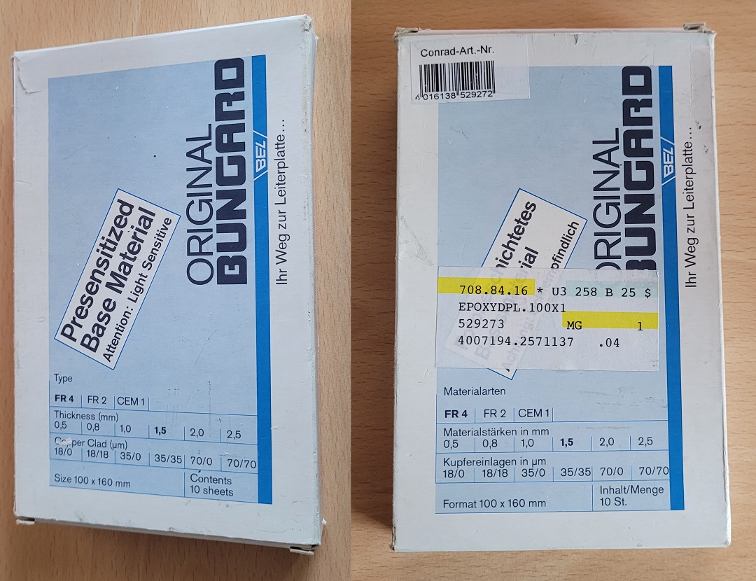
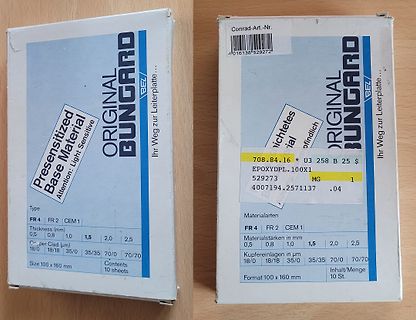
ORIGINAL BUNGARD BEL/ Ihr Weg zur Leiterplatte... Presensitized Base Material Attention: Light Sensitive 708.84.16 * U3 258 B 25 $ EPOXYDPL.100X1 529273 MG 4007194.2571137 .04 Materialarten FR 4 FR 2 CEM 1 Materialstärken in mm 0,5 0,8 1,0 1,5 2,0 2,5 Kupferlagen in µm 18/0 18/18 35/0 35/35 70/0 70/70 Size 100 x 160 mm Contents 10 sheets Format 100 x 160 mm Inhalt/Menge 10 St.
and the handlers for low priority level interrupts from being executed (For example, if the time-base timer interrupt is enabled, stepping over the RETI instruction will always break on the first line of the time-base timer interrupt handler). Disable the corresponding interrupts when the corresponding
Iz FIP200/300 Series 10 OUTPUT 701 ; "Ml" 20 OUTPUT 701; "OPMF" 30 ENTER 701;M 40 IF M <1E9 TH EN 70 50 OUTPUT 701; "FDP' 60 GOTO 30 70 IF M 1E9 TH EN 100 80 OUTPUT 701; "FU" 90 GOTO 30 100 END 6 - 1 4 O ct 20/89 R4131 SERIES SPECTRUM ANALYZER .[NSTRUCTION MANUAL - - - 6 .4 S e ttin g o f E a c h F
auch moch RPG am werkeln. Allerdings hatte man(n) bei der IBM schon früh erkannt (so Ende der 70ger) glaube ich dass es Lieferprobleme mit Lochkarten geben könnte. Deshalb hatte man einen Programmiereditor entworfen - ich glaube der hiess WSU - der Lochkarten ähnliche Eingaben gestatte. Der Sinn von RPG? RPG war eine prozedurale Sprache die Datenbank Funktionen - ähnlich wie später dBase - inne hatte. Das war natürlich für Verwaltungs-/Kaufmännische Anwenungen optimal. Ciao Günther
#7464990: > Ich kann da nichts auffälliges entdecken, allerdings ist der Takt, den > du erzeugst ca 70kHz, aber funktionieren sollte das. > > Du brauchst also schon nen Oszi oder LA um das sinnvoll auswerten zu > können. Das mit den 70KHz ist schon OK. Habe Pulseview. Oder sagen wir so, mit den 70 KHz ist so eine Geschichte :) Aber da müßte ich weiter ausholen. Vielleicht später (aber das fällt vielleicht unter die Rubrik: mein größter Bock).
parts over temperature and voltage as mounted on evaluation board or in sockets. f tr tSU.DAT SDA 70% 70% 30% 30% tf continued below At SCL tr 70% tD.DAT 70% HD.DAT 30% 30% 9tclock cycle S tHD.STA st/fSCL LOW 1 clock cycle tHIGH tBUF SDA 70% A 30% SU.STA HD.STA tVD.ACK tSU.STO SCL 30%0% th Sr 9 clock
otherwise specified: V = 5 V, SHDN pin is tied to V . IN IN 100 100 90 90 80 VIN 10V 80 V IN10V ) ) % 70 VIN 5V ( 70 VIN 5V ( Y C 60 VIN 3.3V C 60 N E I 50 C 50 I F F 40 F 40 E E 30 30 20 20 10 10 0 0 0 100 200 300 400 500 600 700 0 50 100 150 200 250 300 350 400 LOAD CURRENT (mA) LOAD CURRENT (mA) Figure
Mix setzen muss. Und trotz PV-Totalausfalls wurden letzte Woche (KW 50) eben doch in Summe fast 70% unseres Stroms aus Erneuerbaren hergestellt: https://www.energy-charts.info/charts/energy_pie/chart.htm?l=de&c=DE 70%, für die wir weder von anderen Rohstoffe einkaufen mussten noch die Umwelt
Beitrag #7556503: > Und trotz PV-Totalausfalls wurden letzte Woche (KW 50) eben doch in > Summe fast 70% unseres Stroms aus Erneuerbaren hergestellt: > > https://www.energy-charts.info/charts/energy_pie/chart.htm?l=de&c=DE > > 70%, für die wir weder von anderen Rohstoffe einkaufen mussten noch die
to Once the tube ionised, as there is effectively a short lower power consumption (typically about 70% circuit across C4, the operating frequency is defined of that with conventional ballast), longer tube lifeby C3 only, and so is lower. At this frequency the and almost no flicker. overvoltage generated
67 103 104 105 106 107 24 PCM_IN RXD 68 23 SD_INS_DET USB_DP 69 22 GND 108 109 110 111 112 USB_DM 70 21 PWRKEY USB_VBUS 71 20 RESET_N C N N T K _ M L D P S T D C _ X R R A V GND 72 v S _ _ _ _ _ _ I I E 2 19 GND e N H H I I I M G M M I R 117 L 118 E 119 E 120 G 121 G 122 G 123 S 124 S 125 S 126 P127
are RoHS XXX MG Compliant G CASE 318 STYLE 6 1 MAXIMUM RATINGS (TA= 25°C) Rating Symbol Max Unit SC−70/SOT−323 XX MG CASE 419 Collector−Base Voltage V CBO 50 Vdc G STYLE 3 Collector−Emitter Voltage V CEO 50 Vdc 1 SC−75 Collector Current − Continuous C 100 mAdc XX M CASE 463 Input Forward Voltage VIN(fwd
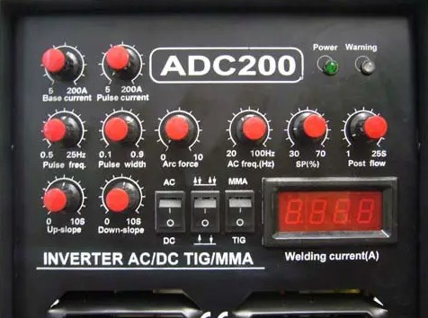
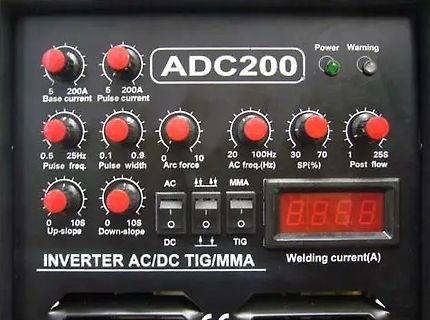
ADC200
Power Warning
5 200A Base current
5 200A Pulse current
0.5 Pulse freq.
0.1 0.9 Pulse width
0 Arc force 10
20 100Hz AC freq.(Hz)
30 70 SP(%)
1 25S Post flow
0 10S Up-slope
0 10S Down-slope
AC MMA
DC TIG
8.8.8.8
Welding current
0.47 A A/B 0.68 A A A/B 1.00 A A A B 1.50 A A A A/B B/C 2.20 A A A/B B B B/C 3.30 A A A/B B B/C C 4.70 A A/B B B/C C C/D 6.80 A/B B B/C C C/D D 10 A/B B/C B/C C C/D D 15 B/C B/C C C/D D D 22 B/C C C/D D D E 33 C C/D D D E 47 C/D D D E 68 D D D E 100 D D E 150 D E 220 E E 330 E • LEAKAGE CURRENT (µA) U
time V COM = VCC, CL= 35 pF, ns ON R L 300 Ω, see Figure 17 Full 2.3 V to 120 2.7 V 25°C 2.5 V 22 70 OFF Turnoff time V COM = VCC, CL= 35 pF, ns R L 300 Ω, see Figure 17 Full 2.3 V to 70 2.7 V BBM Break-before-make See Figure 18 25°C 2.5 V 1 7 ns time QC Charge injection V GEN= 0, RGEN = 0 CL= 1 nF,
der Nachbarn" machen konnte. Alles hat sich verlagert. Die VHF Systeme waren schnell abgelöst, durch 70cm Systeme (Ja, damalige Funkkopfhörer sendeten mitten im 70cm AFU Band, keine Ahnung wieso das so koordiniert wurde) bis hin zum ich sage mal "letzten analogen System" das sich zwischen 863...865MHz
Eigentlich ist es nur noch der CB-Funk, 10m AFU, 6m AFU, UKW Rundfunk, Flugfunk, 2m AFU, Freenet, 70cm AFU und PMR446. Wobei auch hier so langsam die Digitalisierung Einzug hält. Bekanntes Beispiel vor der Abschaltung der vielen LW, MW und KW Sender war der Digitale Sendeversuch mit DRM. Viele
20 V I @ T = 25°C Continuous Drain Current, @ 4.5V 4.2 D A GS ID@ T A 70°C Continuous Drain CurrentGS@ 4.5V 3.4 A IDM Pulsed Drain Current 33 P @T = 25°C Power Dissipation 1.25 D A W PD@T =A70°C Power Dissipation 0.8 Linear Derating Factor 0.01 W/°C VGS Gate-to-Source Voltage
% per day 30 ≤ Temp <40 2Y% per day 40 ≤ Temp <50 4Y% per day 50 ≤ Temp <60 8Y% per day 60 ≤ Temp <70 16Y% per day 70≤ Temp 32Y% per day CAPACITY vs TIME 1200 1000 h 800 A m TA= 15°C – i 600 a T = 25°C a A C 400 TA= 35°C 200 TA= 45°C 0 0 10 20 30 40 50 60 70 Time – Days Figure 4. Self-Discharge at 2.5%
approach is preferred. In most cases, a Colpitts oscillator is successfully used. Circuits with grounded base exhibit severe stability problems and even the Colpitts oscillator, based on its emitter circuitry, shows ocassional unwanted resonances up to 6GHz. This is due to the fact that the modern Si and SiGe
Vorab: Test in der Konsole... C:\Users\Privat>cargo --version cargo 1.70.0 (ec8a8a0ca 2023-04-25) C:\Users\Privat> C:\Users\Privat>clang --version clang version 16.0.0 Target: x86_64-pc-windows-msvc Thread model: posix InstalledDir: C:\Program Files\LLVM\bin
- Enable four-operand fused multiple-add. fsgsbase - Support FS/GS Base instructions. fsrm - REP MOVSB of short lengths is faster. harden-sls-ijmp - Harden against straight line speculation across indirect JMP instructions

 Bild
 Bild
 Bild