-
 Bild
Bild
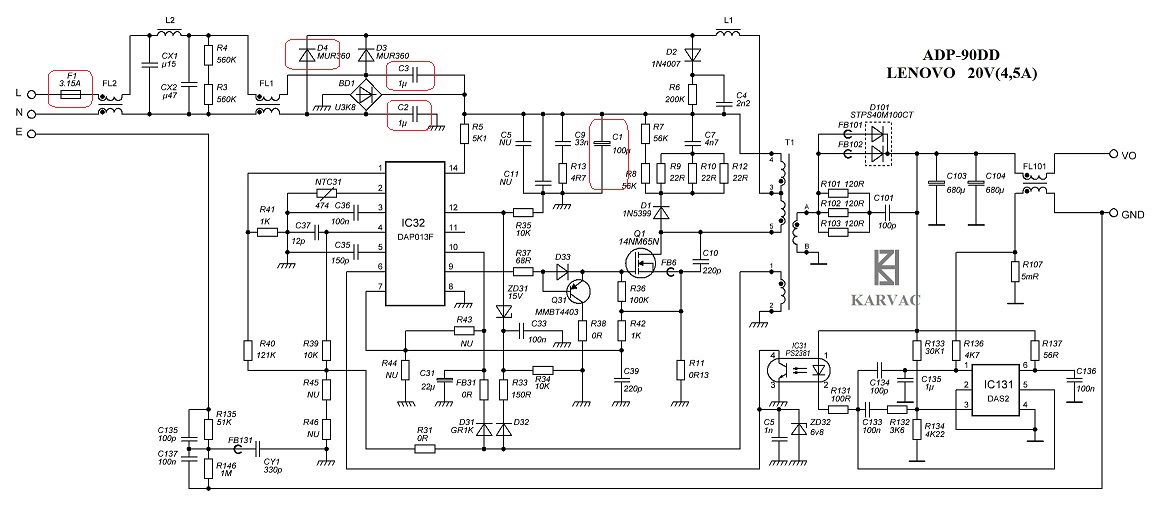
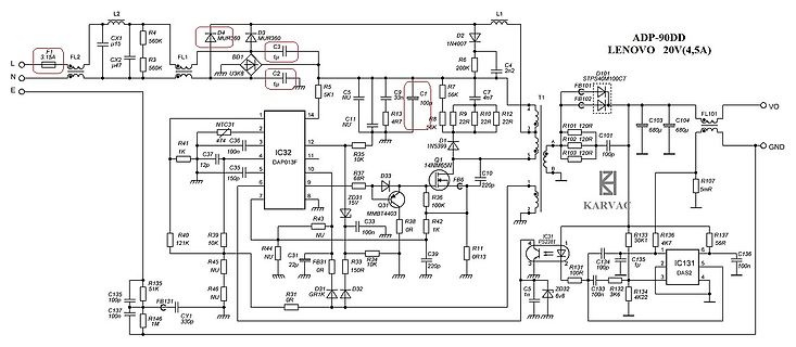
Schaltplan eines Lenovo 20V Netzteils
ADP-90DD LENOVO 20V(4,5A) L F1 FL2 R4 560K CX1 uF R3 560K N E D4 MUR360 D3 MUR360 C3 uF BD1 U3K8 C2 uF R5 5K1 C5 NU R7 56K C9 33n C1 100n R6 200K D2 1N4007 L1 C4 2n2 R9 R10 R12 22R 22R 22R R101 120R C103 68u FB101 T1 C104 68u FL1 VO R102 22R C101 100p R103 22R GND Q1 14N65N R35 10K R37 68C D1 1N5819 IC32 DAP013F NTC31 474 C36 100n R41 1K C37 12p C35 150p R40 121K R39 10K R44 NU R45 NU R46 NU R31 0R R33 10K R34 150R R36 100K R38 1K R42 1K R43
-
 Bild
Bild
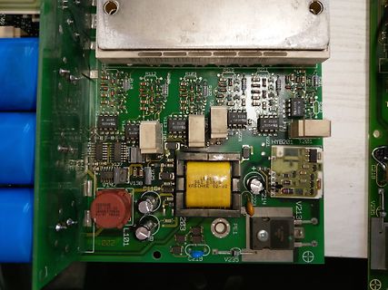
Nahaufnahme einer Leiterplatte mit elektronischen Bauteilen
R112 R103 R219 R211 A 3120 020691 A 3120 020691 A 3120 020691 A 3120 020691 HYB201 T201 V137 V138 V125 V124 V213 V214 V235 V235 C116 C119 L101 L101 203 PE1 KWSKCHE 131316 V1 LENSZ37563A 43/01 168uH 352 638/6
-
 Bild
Bild
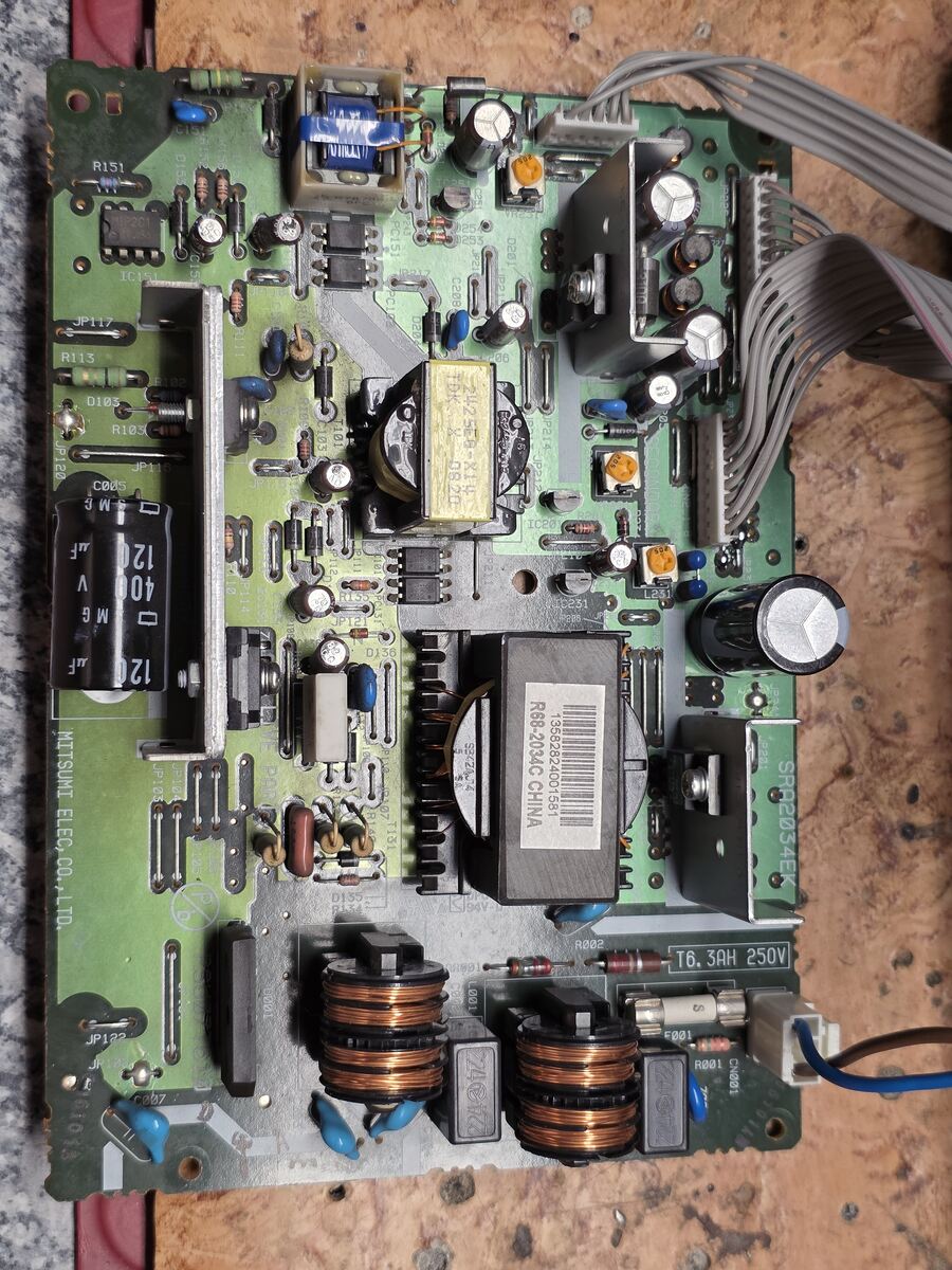
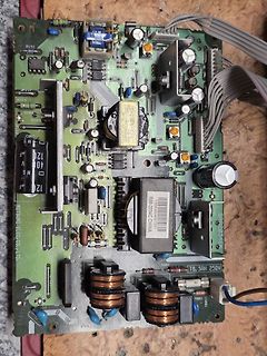
Leiterplatte eines Schaltnetzteils
R151 IC1 R113 D103 R105 120 uF 40 V M G 120 uF M G MITSUMI ELEC. CO., LTD. JP122 R101 D101 R102 D102 R104 D105 R106 D107 R108 D109 R110 D111 R112 D112 R114 D115 R116 D117 R118 D119 R120 D120 R121 D121 R122 D122 R123 D123 R124 D124 R125 D125 R126 D126 R127 D127 R128 D128 R129 D129 R130
-
 Bild
Bild
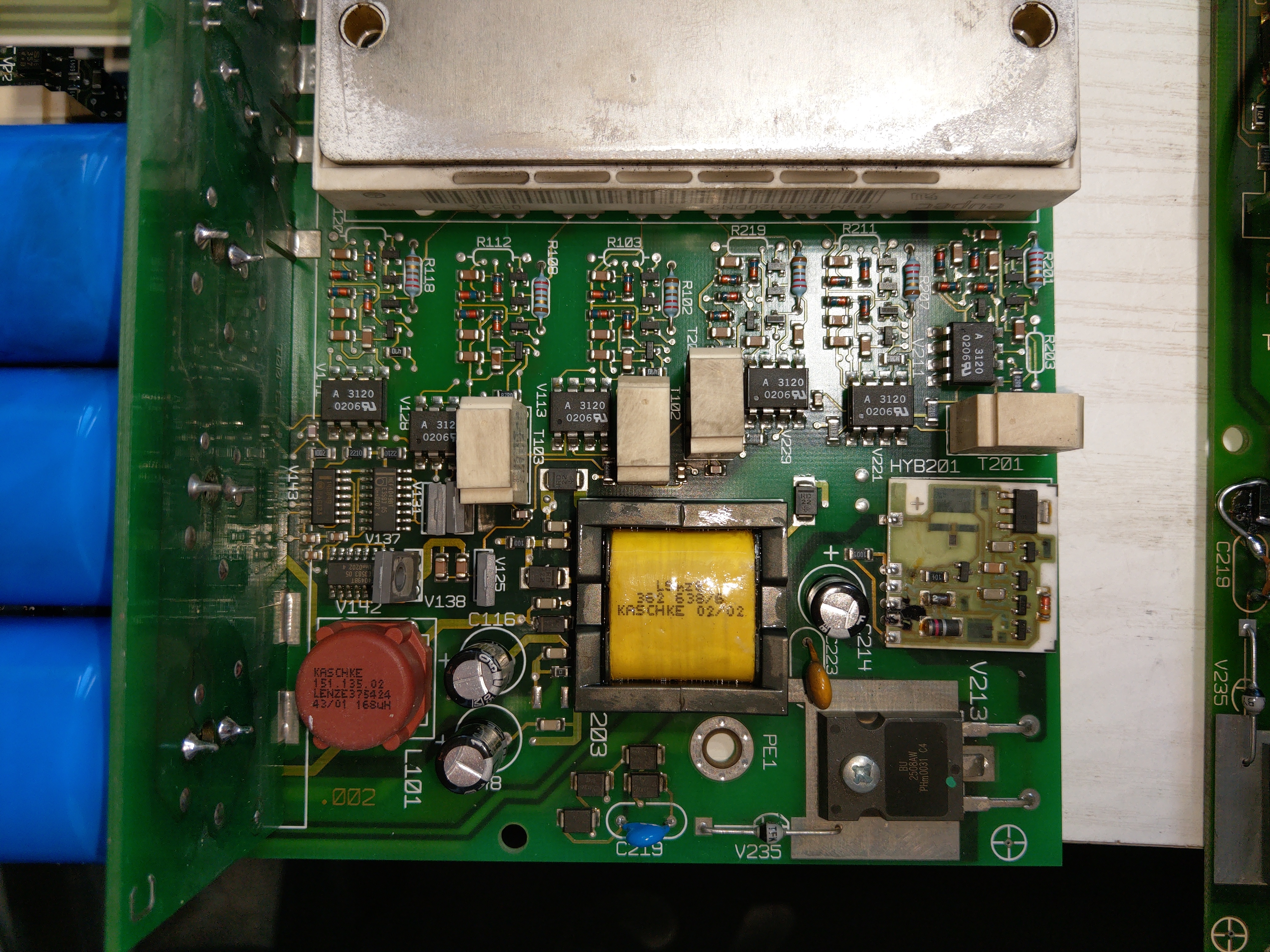
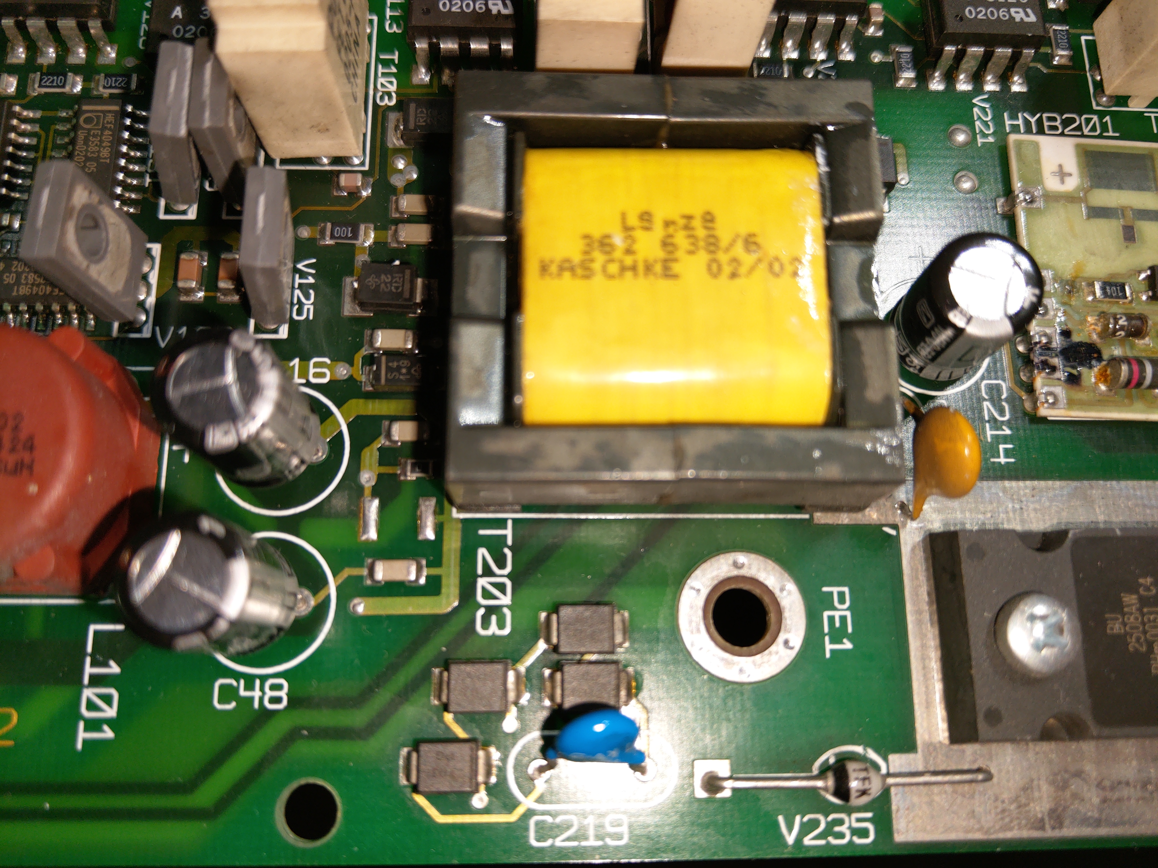
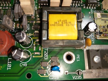
Nahaufnahme einer Leiterplatte mit Transformator und Bauteilen
A 3 020 0206 10 113 L1103 HYB201 V125 16 362 638/6 KASCHKE 02/02 C214 L101 C48 T203 PE1 C219 V235
-
 Bild
Bild
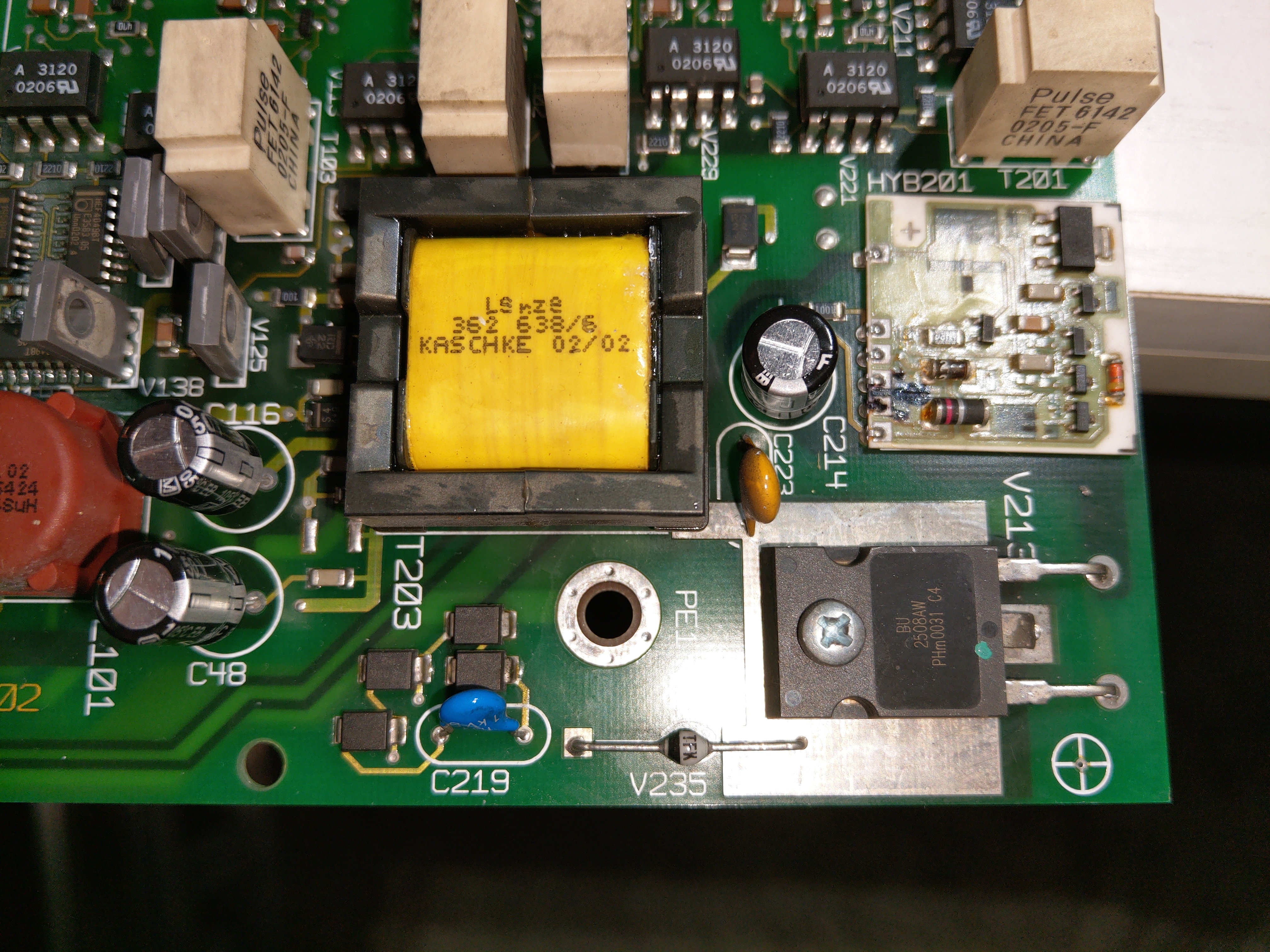
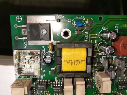
Nahaufnahme einer Leiterplatte mit Transformator und Bauteilen
V235 C219 V215 BU 250W C4 48 T203 101 C48 V125 V138 V121 T201 HYB201 CHINA 070514 T103 PULSE 842 0206J A 3120 0206J A 3120 0206J A 3120 LS 362 636/6 KAS CHKE 02/02
-
Thread
"7D621K": Händler und Alternativ-Bezeichnungen? Können die Durchschlagen, aber noch OK sein?
TDK-Epcos ist auch genannt: https://www.digikey.de/de/products/detail/epcos-tdk-electronics/B72207S0381K101/651537 "Auf Lager: 33.324"
135409441083?srsltid=AfmBOorbjbPClAvhjjoIS_WzZGGaCt2AsjvHGf5ButGeKoGb8OTpHFB9 und in Europa heissen 7mm 1mA@620V VDR halt 385V VDR wie https://www.buerklin.com/de/p/tdk-epcos/varistoren/b72207s0381k101/82E2332/ Ein Ersatz darf grösseren Durchmesser haben und +/-15V abweichen, günstig https://www.pollin.de
-
Artikel
ARM-ASM-Tutorial
subs r3, #1 8000164: bf1c itt ne 8000166: 7003 strbne r3, [r0, #0] 8000168: e012 bne.n 8000190 800016a: f101 0101 add.w r1, r1, #1 800016e: f1b1 0f11 cmp.w r1, #17 8000172: d202 bcs.n 800017a 8000174: 4a14 ldr r2, [pc, #80] ; (80001c8 ) 8000176: 5c53 ldrb r3, [r2, r1] 8000178: 7003 strb r3, [r0, #0] 800017a
8000190: 4770 bx lr 08000192 : 8000192: 0202 0202 0202 0205 0205 0205 0202 0202 ................ 80001a2: . 080001a3 : ... 080001a4 : 80001a4: 490a ldr r1, [pc, #40] ; (80001d0 ) 80001a6: 6808 ldr r0, [r1, #0] 80001a8: f040 0004 orr.w r0, r0, #4 80001ac: 6008 str r0, [r1, #0] 80001ae: 4770 bx lr 080001b0
-
Thread
Heizstab an PV Module
a3kln.
PV Modul die verfügbar ist, sondern nur Strom x Widerstand für ihre 53 Ohm, also [pre] 33000 lux 5A 265V 1325W kritisch 10000 lux 1.5A 79.5V 120W 6600 lux 1A 53V 53W 3300 lux 0.5A 26.5V 13.35W [/pre] und in Leerlaufbegrenzung [pre] 100000 lux 10A 290V 4600W durchgebrannt 50000 lux 7.5A 280V
-
 Bild
Bild
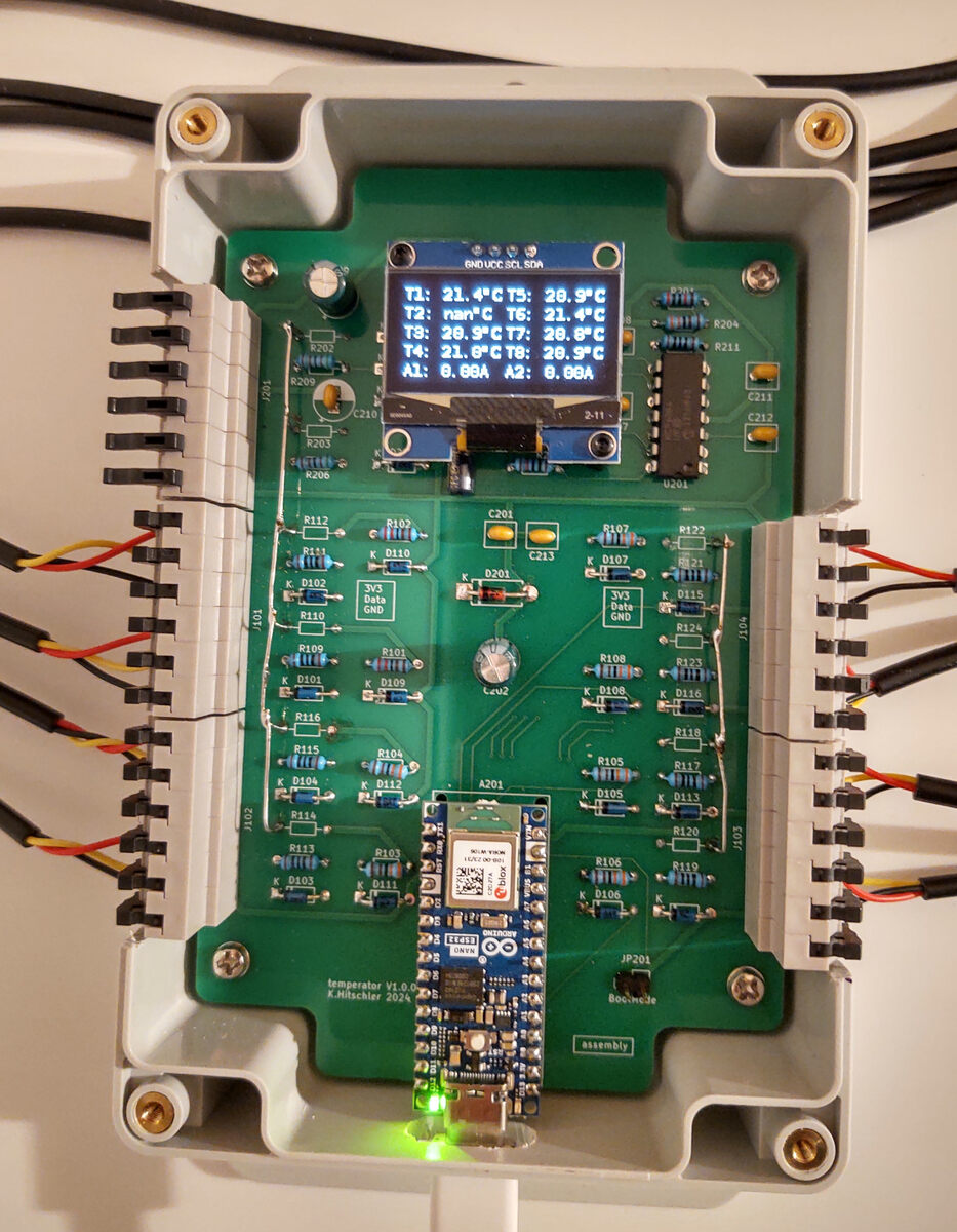
Leiterplatte mit Display und Mikrocontroller-Modul
T1: 21.4°C T5: 20.9°C T2: nan°C T6: 21.4°C T3: 20.9°C T7: 20.8°C T4: 21.0°C T8: 20.9°C A1: 0.68A A2: 0.68A GND VCC SCL SDA R201 R203 R204 R211 C210 C211 C212 C213 R102 R107 R122 R106 R108 R124 R105 R116 R117 R120 R103 R104 R114 R115 R116 R101 R109 R110 R111 R112 R113 R101 bis R124 D101 bis
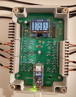
-
 Bild
Bild
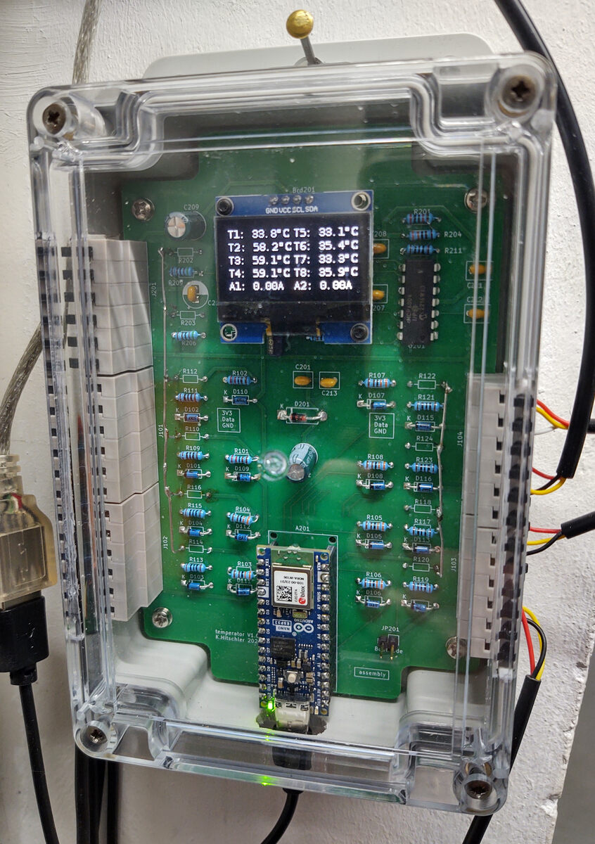
Elektronik-Projekt in Kunststoffgehäuse mit Display und Mikrocontroller
T1: 33.8°C T5: 33.1°C T2: 59.2°C T6: 35.4°C T3: 59.1°C T7: 33.3°C T4: 39.1°C T8: 35.9°C A1: 0.88A A2: 0.88A C209 R201 GND VCC SDA SCL R208 R204 R211 C207 R203 R206 R112 R102 C201 R122 R107 C213 D107 R121 D110 D105 R108 R106 R105 R104 R103 R102 R101 R111 D106 D104 D102 D101 R110 R111 ESP-12E
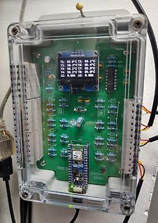
-
 Bild
Bild
Leiterplatte eines Schaltnetzteils mit Kühlkörpern
MPE-112-A, CG01, CG02, CG03, CG101, SK-2H35, L101, L102, OUT1, L1:2.30mm
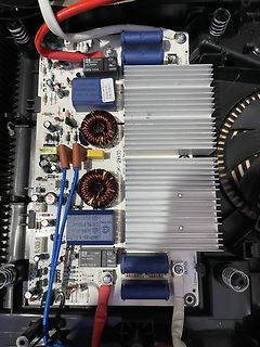
-
Thread
Raspberry Pi Pico SDR
das runtergemischte ZF-Signal digital prozessiert. https://www.norcalqrp.org/files/Tayloe_mixer_x3a.pdf
Kann man im Menü unter Hardware/IF anpassen. Dawson schreibt dazu in seiner Doku: "The receiver uses a low IF so the wanted signal is always offset from DC by a few kHz."
-
Thread
PeakTech 365eff
die Sicherungen defekt sind und z.B. der Vorgänger sie nicht ersetzt hat. Aufdruck am Multimeter 20A und 400 mA (Innen sind die Sicherungssockel Leer also kein Anhaltspunkt was die Originalen waren; ich würde z.B. 20A Träge und 500 mA Flink da für 20A keine mit 21A Flink oder ähnliches findet. Bei
Sicherungen defekt sind > und z.B. der Vorgänger sie nicht ersetzt hat. Aufdruck am Multimeter 20A > und 400 mA (Innen sind die Sicherungssockel Leer also kein Anhaltspunkt > was die Originalen waren; ich würde z.B. 20A Träge und 500 mA Flink da > für 20A keine mit 21A Flink oder ähnliches findet
-
 Bild
Bild
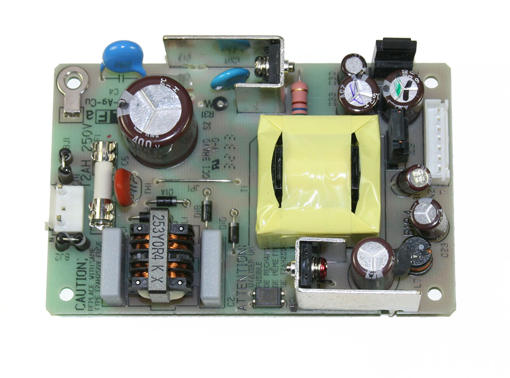
Leiterplatte eines Schaltnetzteils
A9-Cu 250V 2AH 400V C5 C6 C7 C8 C9 C10 C11 C12 C13 C14 C15 C16 C17 C18 C19 C20 C21 C22 C23 C24 C25 C26 C27 C28 C29 C30 C31 C32 C33 C34 C35 C36 C37 C38 C39 C40 C41 C42 C43 C44 C45 C46 C47 C48 C49 C50 C51
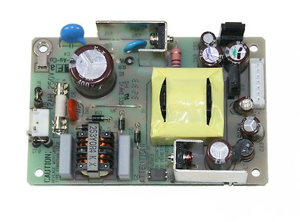
-
 Bild
Bild
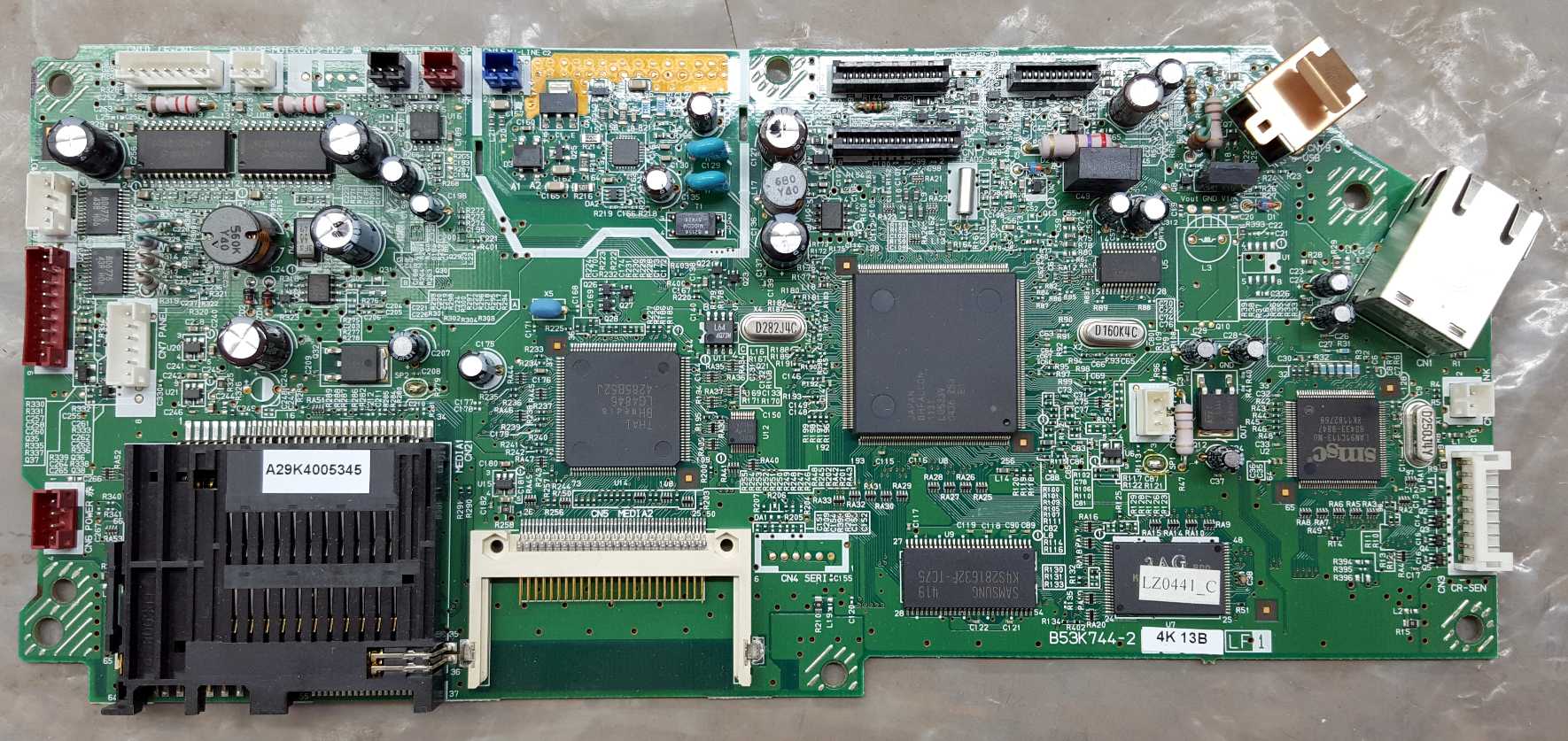
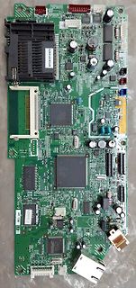
Foto einer grünen Leiterplatte mit elektronischen Bauteilen
A29K400S345, CN1, CN2, CN3, CN4, CN5, CN6, CN7, CN8, CN9, CN10, CN11, CN12, CN13, CN14, CN15, CN16, CN17, CN18, CN19, CN20, CN21, CN22, CN23, CN24, CN25, CN26, CN27, CN28, CN29, CN30, CN31, CN32, CN33,
-
 Bild
Bild
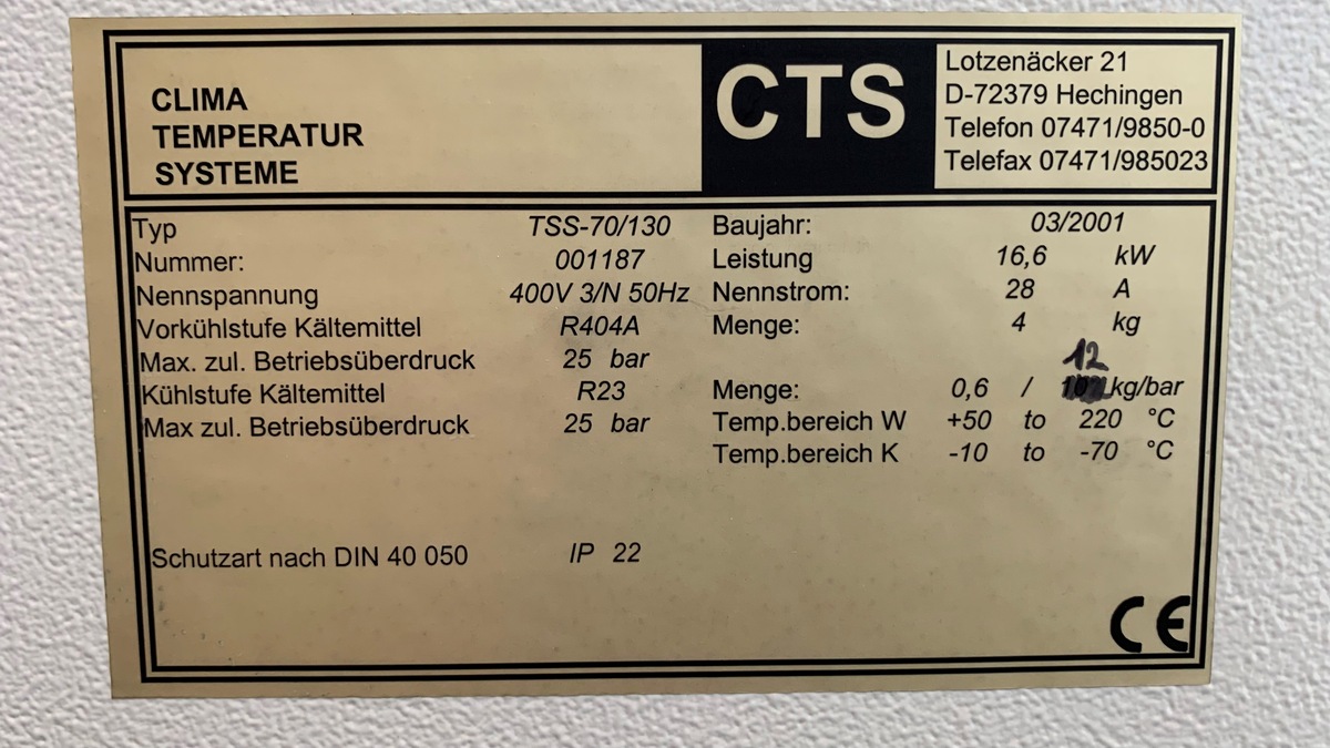
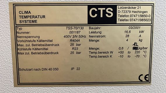
Typenschild einer Klimaanlage
07471/985023 Typ TSS-70/130 Nummer: 001187 Nennspannung 400V 3/N 50Hz Vorkühlstufe Kältemittel R404A Max. zul. Betriebsüberdruck 25 bar Kühlstufe Kältemittel R23 Max zul. Betriebsüberdruck 25 bar Baujahr 03/2001 Leistung 16,6 kW Nennstrom 28 A Menge: 4 kg Menge: 0,6 / 101 kg/bar Temp.bereich W +50 to
-
Thread
Ladegerät Kettler pedelec von 2011
wir haben (weil im www solch ein Fall beschrieben ist) ersetzt: 1. ein Mosfet des Schaltnetzteils (Q101), ein R6015ANX. N-Channel Mosfet mit 15A/600V. 2. den fetten Elko, 220 µF, 450 V, 105°C, 2000h Es hat beides an der Situation nichts geändert. Das Ladegerät lädt den Akku nicht mehr, und der Akku
Panasonic NKJ051A
-
Thread
Arduino-IDE mit ESP32
name. Error code: 3', main.rs:65:9 note: run with `RUST_BACKTRACE=1` environment variable to display a backtrace exit status 101 C:\Program Files (x86)\Arduino\arduino-builder gab 101 zurück Fehler beim Kompilieren für das Board ESP32 Dev Module. Selbst der einfachste Sketch wird nicht übersetzt
name. Error code: 3', main.rs:65:9 note: run with `RUST_BACKTRACE=1` environment variable to display a backtrace exit status -1073740791 Fehler beim Kompilieren für das Board ESP32 Dev Module. Fehler im eigenen Code und in der Library schließe ich aus. Meine Forschungen erbrachten bis jetzt, daß
-
Thread
Fehlersuche CCFL Vorschaltgerät PCB
Platine 1:1 die selbe ist wie die im Bild von mir? Aufdruck auf der Platine selbst ist bei beiden "CNL21-101 V1", jedoch gibt der Verkäufer bei Aliexpress an, sie wäre für ein anderes Display: - Angabe Verkäufer JL150AT490A-V0 DG5-012V-15A1040 - Angabe Aufkleber auf meiner Platine: JL215AT640D-V1 DG5-012V-21A1025
-
 Bild
Bild
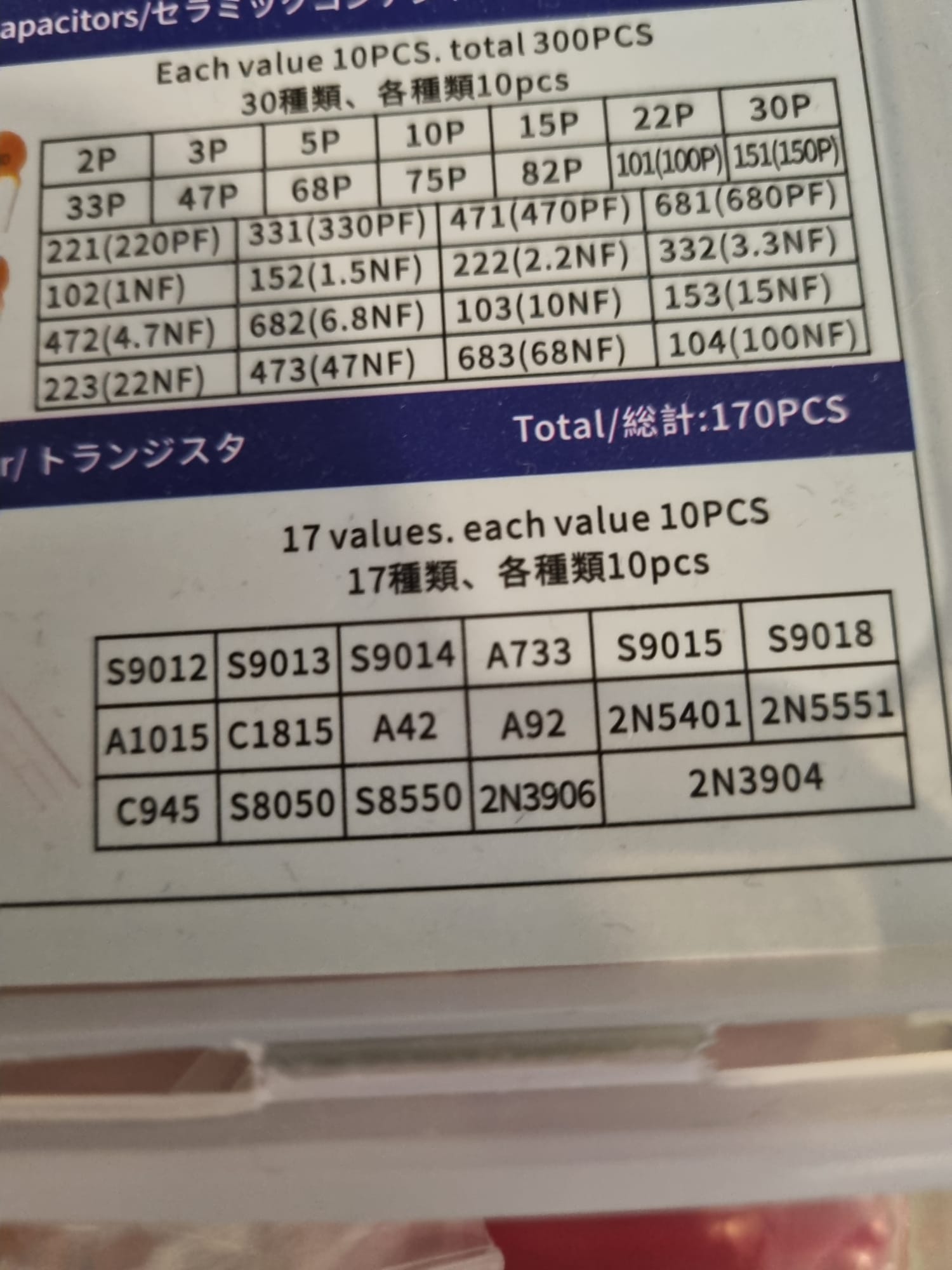
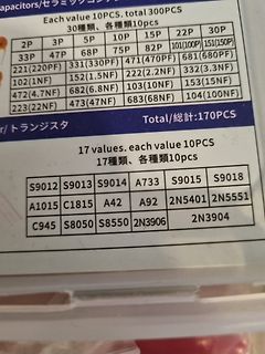
Liste von Kondensator- und Transistorwerten
Each value 10PCS. total 300PCS 30種類、各種種類10pcs 2P 3P 5P 10P 15P 22P 30P 33P 47P 68P 75P 82P 101(100P) 151(150P) 221(220PF) 331(330PF) 471(470PF) 681(680PF) 102(1NF) 152(1.5NF) 222(2.2NF) 332(3.3NF) 472(4.7NF) 682(6.8NF) 103(10NF) 153(15NF) 473(47NF) 683(68NF) 104(100NF) Total/総計:170PCS 17 values. each value 10PCS 17種類、各種種類10pcs S9012 S9013 S9014 A733 S9015 S9018 A1015 C1815 A42 A92 2N5401 2N5551 C945 S8050 S8550 2N3906 2N3904
-
Thread
Nachbildung einer Von-Neumann-Architektur will "atmen"
eintragen und das Programm dann durchlaufen lassen möchtet? Einen Simulator benutzen: https://www.101computing.net/LMC/
* Programm uebersetzen, in VHDL-ROM-Form bringen, Testbench nudeln lassen * Signale mit GTKWave o.ae. anschauen Wie das im Notebook grundsaetzlich laeuft, kann man hier sehen: https://github.com/pcornier/1pCPU.
-
Thread
Nachlassauflösung, AVRs, Oszi, MM, Bücher, div. Bauteile
4x Batteriehalter Micro 003: 5x Batteriehalter Mignon 004: Mean Well Schaltnetzteil, 25W 12V 2,1A Mean Well Schaltnetzteil, 25W 24V 1,1A 005: Wicked Chili Akku für Fritz!Fon 006: 10x Peltier-Elemente TEC1-12706, 15V 6.4A 65W 007: 100m Aircell 7 Koax-Kabel 008: RF Explorer 009: Metrovna
Antennenrotor 011: 2x Diamond SS-500 Antennensplitter 012: profitec SPS12402 Schaltnetzteil, 12V..14V 4A 013: Kenwood FM Dual Band Tuner TM-G707 014: MFJ-834 RF Amperemeter, 3A 015: Daiwa SWR & Power Meter CN-103L 016: Daiwa SWR & Power Meter CN-101L 017: Diamnond Antenna Antennenfuss für UKW Vertikalstrahler
-
Thread
Welches Bauteil ist das?
Steffen N. schrieb im Beitrag #7837463: > Danke erst mal. Überbrücken von A nach B oder A nach C? Brücken bei PR101 und PR102.
im Beitrag #7837471: > Steffen N. schrieb im Beitrag #7837463: >> Danke erst mal. Überbrücken von A nach B oder A nach C? > > Brücken bei PR101 und PR102. A+C brücken und B+D brücken. Einfach die Kästchen von PR101 und PR102 ausmalen ;)
-
Thread
[S] 2N2646 Unijunction-Transistoren
datasheets/2N602X.pdf https://www.electroschematics.com/programmable-unijunction-transistor-put-a-quick-rescript/ https://www.ovaga.com/blog/transistor/2n6027-transistor-datasheet-pinout-equivalent-and-uses#:~:text=2N6027%20Transistor%20Uses,-The%202N6027%20transistor&text=By%20generating%20precise
schrieb im Beitrag #7845197: > Es gibt da noch die "programmierbaren" 2N6027. Oder den BRY56, BR101, BRY39. Wenn's pressiert, kann man sich solch einen PUT auch leicht aus einem pnp- und einem npn-Transistor zusammenkleben: Einfach die Basen des Einen mit dem Kollektor des jeweils Anderen verbinden
-
Thread
PT4115E Treiber Platine Probleme
Treiber auf 500mA eingestellt also ich schätze mal da sollte ich so 0.7-1A haben. Fehlende Pull-Downs, schlechter Spannungswandler, input only GPIOs sind mir bekannt :) Würde mich über alle Tipps hier freuen, das
aber auch mit 2-Lagen ohne Probleme hinbekommen. War für etwas mehr Strom ausgelegt, könnte für 500mA noch etwas kleiner ausfallen
-
 Bild
Bild
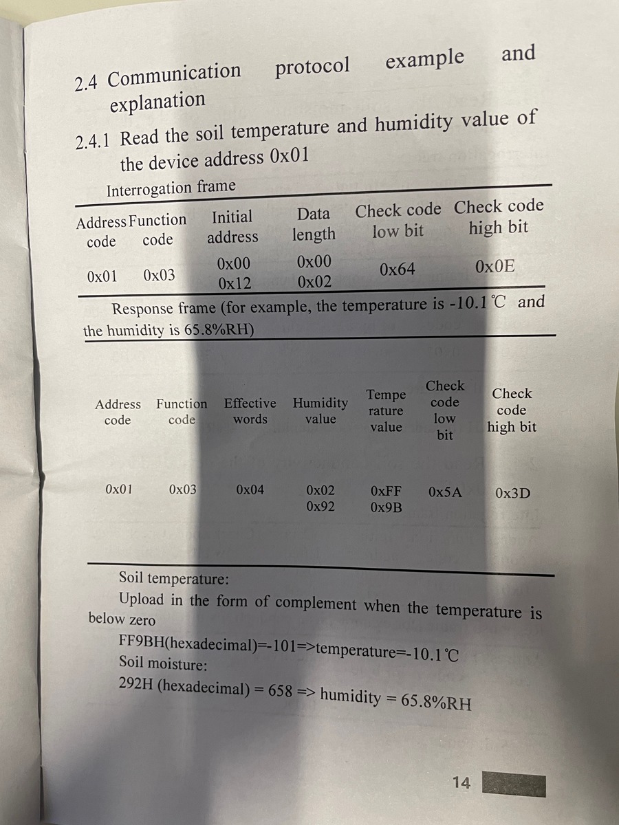
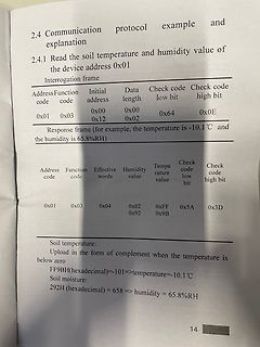
Dokumentation eines Kommunikationsprotokolls für Bodenfeuchtigkeit und Temperatur
code 0x03 Effective words 0x04 Humidity value 0x02 Temperature value 0xFF 0x9B Check code low bit 0x5A Check code high bit 0x3D Soil temperature: Upload in the form of complement when the temperature is below zero FF9BH(hexadecimal)=-101=>temperature=-10.1°C Soil moisture: 292H(hexadecimal) = 658 => humidity
-
Thread
Schaltnetzteil / Lader defekt
Wolfgang H. schrieb im Beitrag #7835182: > Lader mit 2A. Für 60W ist dein MOSFET zu hochohmig.
Ist das R12 mit 100k ? dann wären es 1625/101 =16kHz
-
 Bild
Bild
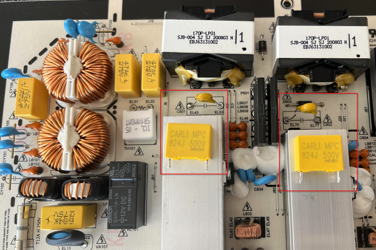
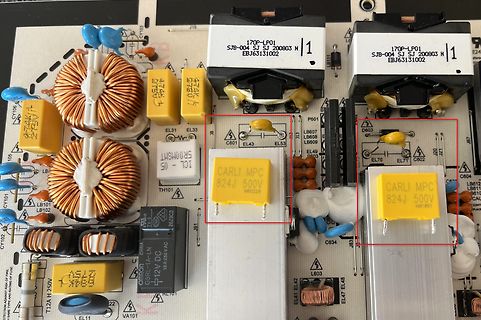
Nahaufnahme einer Leiterplatte mit Leistungselektronik
LB607 LB608 LB609 C801 EL43 EL53 D603 EL70 EL71 C602 CARLI MPC 824J 500V M61851 C634 LB603 EL47 EL48 LB101 LB102 CY101 CY102 EL11 T12A H 250V VA101 GRSL-1A 12V DC
-
Thread
ARM-AI-Assistent final, RP2040 mit 200 MHz Maximaltakt uvm
Zertifikation des Chips für diese schnellere Taktrate: [c] RP2040 has now been certified to run at a system clock of 200Mhz when using a regulator voltage of at least 1.15 volts. . . . With this version of the SDK, you can now select a 200Mhz clock for RP2040 simply by setting SYS_CLK_MHZ=200 via
> RP2040 has now been certified to run at a system clock of 200Mhz > when using a regulator voltage of at least 1.15 volts. > With this version of the SDK, you can now select a 200Mhz clock > for RP2040 simply by setting SYS_CLK_MHZ=200 via
-
 Bild
Bild
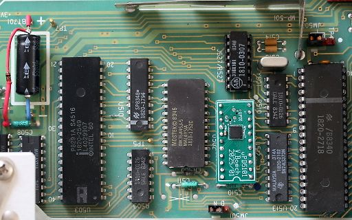
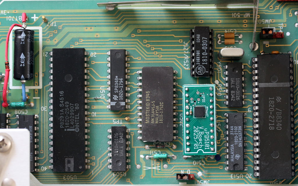
Nahaufnahme einer Leiterplatte mit integrierten Schaltkreisen
BT701 MP-501 TP7 C519 JM501 TP4 101 8340 310101 1810-0307 AB 527/A527 1810-0126 DALE 8342 1822-2718 B8340 MALAYSIA 31V4 SW74578N 20 U513 2025/01 UPD5101 V. Bosch 0502 C508 30 U503 P8291A S4516 1820-2549 L4029907 INTEL '80 U519 SPB348*