if sharing Arduino reset pin) #define SCREEN_ADDRESS 0x3C ///< See datasheet for Address; 0x3D for 128x64, 0x3C for 128x32 Adafruit_SSD1306 display(SCREEN_WIDTH, SCREEN_HEIGHT, &Wire, OLED_RESET); #define NUMFLAKES 10 // Number of snowflakes in the animation example #define LOGO_HEIGHT 16 #define LOGO_WIDTH
Sebastian H. schrieb im Beitrag #7628941: > Prozessor AVR128DB28 AVR128DB28 ist kein Prozessor, sondern ein Controller.
Maxim B. schrieb im Beitrag #7631166: > in ersten PDF für AVR128DB steht wie für meisten MEGA auch 10 000 > Flashprogrammierungen Mutmaßlich einer der vielen Copy & Paste Fehler beim Übertragen von Passagen aus alten Datenblättern. Der Mega128 etwa hatte noch
Max M. schrieb im Beitrag #7628754: > Nach 2 TAgen geht an 2 von 3 Geräten plötzlich Tastatur und Touchpad > nicht mehr. > Einige recherche im Netz, ist normal!!!! Ja Max, das ist vöööööllllig normal
Max M. schrieb im Beitrag #7628784: > Anstatt mal gemeldete Probleme ernst zu nehmen … Max, wir nehmen deine Probleme ernst. Darum ja auch der gut gemeinte Rat den Therapeuten zu konsultieren und niemals
connector CN8; RS485 Connector CN10 Note1: The CAN1 and CAN2 inputs/outputs are terminated by R129 and R128 (120 ohm). This means the LandTiger should be located on either end of the CAN bus rather than somewhere in the middle. Note2: The CAN1 may be disabled by removing R74 in CAN1_RX line. That will release
applicable. n S a Symbol Parameter Conditions Standard-mode Fast-mode Fast-mode Plus Unit e l m Min Max Min Max Min Max c [1] o V IL LOW-level input voltage −0.5 0.3V DD −0.5 0.3V DD −0.5 0.3V DD V n [1] [2] [2] [1] [2] d V IH HIGH-level input voltage 0.7V DD 0.7V DD 0.7V DD V u c V hys hysteresis of
AND THIS DOCUMENT ARE SUBJECT TO SPECIFIC DISCLAIMERS, SET FORTH AT www.vishay.com/doc?91000 OLED-128O064D-BPP3N00000 www.vishay.com Vishay 6.Electrical Characteristics Item Symbol Condition Min Typ Max Unit Supply Voltage for Logic VDD ˉ 2.8 3.0 3.3 V Supply Voltage for DisplayVCC ˉ 10 12 15 V Input
GDDRAM is a bit mapped static RAM holding the bit pattern to be displayed. The size of the RAM is 128 x 64 bits and the RAM is divided into eight pages, from PAGE0 to PAGE7, which are used for monochrome 128x64 dot matrix display, as shown in Figure 8-13. Figure 8-13 : GDDRAM pages structure of SSD1306
Active Area / Memory Mapping & Pixel Construction 1.4 Mechanical Drawing 1.5 Pin Definition 2 Abso u e Max mum Ra ng ti s 3. Optics & l E ec trca Cha ac e t ris c s 3.1 Optics Characteristics 3.2 DC Characteristics 3.3 AC Characteristics 3.3.1 I2C Interface Characteristics 3.3.2 I2C Interface with Internal
noisy. Genug 3,5" Einschübe oder 2,5" Schächte für SAS, SATA oder NVMe. Selbst als dual Xeon Gold mit 128GB Ram inkl. RAID Controller für 1500€ ältere unter 200€. Noch lieber mag ich Areca raid Controller. Seit über 15 Jahren kann man ein Raid 6 Abklemmen, an den neusten Controller klemmen und weiterarbeiten
Festplatten mit mehr als 8 TB traue ich irgendwie nicht. Warum das? Langsam drehende Palten nehmen, max 5900 touren und fertig. > Für Tipps wäre ich dankbar. Mainboard mit 6xSATA im ATX Format auswählen. PCI-E auf SATA Expander auswählen, davon gibts auch mit mehr als 6x SATAs. z.B. OMV drauf
latched at the trigger to assist in point placement. There are three decimation modes: normal, min/max, and hires: H Normal (sub-sample) mode throws away samples between saved sample points. H Min/max mode saves the maximum and minimum samples over the decimation interval. H Hires mode gives extra resolution
vom Aliasing kommen könnten - OK - sehe ich aber als unwahrscheinlich.. Update: Kleiner Fehler im max/min scaling behoben.
Max M. schrieb im Beitrag #7637733: > Wenn es die Zeit zulassen würde, möchte ich dich bitten kurz deine > implementation um 1-2 Ordnungen zu erweitern und mit dem Tool der Ulmern > zu schauen ob irgend
Internal slope. in_par_03 none Time constant of the internal bath. in_par_04 none Bandwidth limit (max. difference between the temperatures in the internal bath and external system). in_par_05 none Ratio for max. cooling capacity versus max. heating capacity. in_par_06 none Xp control parameter of the
FREQ_148 * sqrt(A_SQ / accel))/100; // Find out after how many steps does the speed hit the max speed limit. // max_s_lim = speed^2 / (2*alpha*accel) max_s_lim = (long)speed*speed/(long)(((long)A_x20000*accel)/100); [/c] Woher kommt z.B. das /100 im step_delay? Sind das Anpassungen
schon Festpunktberechnungen und -skalierungen, dann wenigstens im Binärsystem mit Faktoren wie 64 oder 128 oder 256, eben "2 hoch irgendwas".
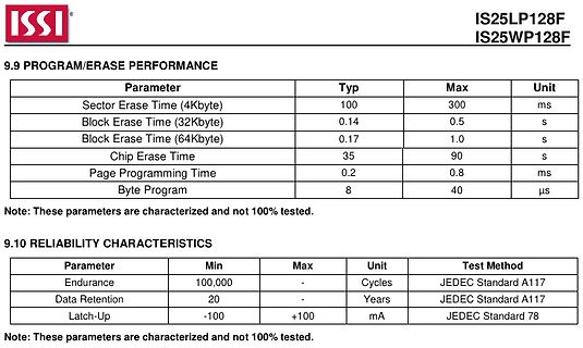
ISSI
IS25LP128F
IS25WP128F
9.9 PROGRAM/ERASE PERFORMANCE
Parameter Typ Max Unit
Sector Erase Time (4Kbyte) 100 300 ms
Block Erase Time (32Kbyte) 0.14 0.5 s
Block Erase Time (64Kbyte) 0.17 1.0 s
Chip Erase Time 35
und die Referenzfrequenz. Außerdem noch die Möglichkeit dual modulus Vorteiler zu benutzen. Die max. Eingangsfrequenz vom Oszillator darf 70 MHz bzw. 30 MHz betragen, also ist der Vorteiler (1:128/129, dual modulus) hier nötig.
10MHz und R = 400 läge die kleinste Schrittweite dann bei fr = 10MHz / R = 25kHz. Da der TBB200 nur max. 30Mhz (Dual-Modulus) verarbeiten kann, muss ein geeigneter Vorteiler (Prescaler) P|(P+1) (z.B. 32/33) die VCO-Frequenz herunterteilen. Bei der max. VCO-Frequenz von 570MHz läge die max.Eingangsfrequenz
...................................................-65°C ~ 150°C Maximum Junction temperature ,T j(max) .................................125°C Static Characteristics VCC = 2.3V to 5.5V; GND = 0V; Tamb= -40°C to +85°C; unless otherwise specified. Symbol Parameter Conditions Min. Typ. Max. Unit Power Supply
Zum Beispiel hier: https://www.az-delivery.de/blogs/azdelivery-blog-fur-arduino-und-raspberry-pi/max98357-was-ist-eigentlich-i2s Vielleicht hilft es dir
> Wenn Du auch für andere Sachen offen bist: > https://www.microchip.com/en-us/product/dsPIC33FJ128MC804 > Der hat einen 14 Bit Stereo DAC. Interessanter Tip. :)
Das PWM-Signal existiert bereits Bei einer Belastbarkeit von 200mA und einer PWM-Frequenz von nur max. 250Hz könnte man sogar auf sämtliche Widerstände verzichten und den N-Mosfet einfach mit einem zwischengeschalteten Push-Pull-Treiber ansteuern.
Versorgungsspannung 13,8V beträgt kann R3 zur Not auch weggelassen werden, dein Mosfet hält schließlich max. 18V (GS-Strecke) aus. Erst ab einer Versorgungsspannung von 18V wird R3 wieder wichtig. R1 sorgt für ein zügiges Abschalten von Q1.
WAIT-Geraffel auszukommen. Also > ich jedenfalls könnte es damit umsetzen. Habe jetzt mal nach AVR128DB64 boards geguckt. Sieht ja soweit okay aus. Aber was meinst Du mit doppeltem Takt? Laut Datenblatt hat der AVR128DB64 eine max clock von 24Mhz, wie alle AVR128DBs ... Dummerweise haben die immer noch
in DIL. > Aber was meinst Du mit doppeltem Takt? Laut Datenblatt hat der > AVR128DB64 eine max clock von 24Mhz, wie alle AVR128DBs Offiziell ja. Tatsächlich laufen sie aber auch mit 32MHz, dann aber nicht über den kompletten spezifizierten Bereich der Umgebungstemperatur. Sprich
Bits Bit 7 – 0: These bits define the backlight PWM output duty cycle. The valid range is from 0 to 128. 0 means backlight completely off, 128 means backlight in max brightness. Register Definition 83 – REG_PWM_DUTY Definition REG_PWM_HZ Definition 31 14 13 0 Reserved r/w Offset: 0xD0 Reset Value: 0xFA
Feature Pb Free Solder Process Non-Pb Free Solder Process Average Ramp Up Rate (T to T ) 3°C / second Max. 3°C / Second Max. s p Preheat - Temperature Min (T sin.) 100°C 150°C - Temperature Max (T sax.) 150°C 200°C - Time (tsMin to s Max) 60 to 120 seconds 60 to 120 seconds Time Maintained Above Critical
habe, CPU-Kern wird bei AVR128 über internen Spannungsregler gespeist, deshalb ist Grenzfrequenz von VCC nicht abhängig.
klein zu bauen, wo nicht so viel gebraucht wird - 16 k SRAM und 128 k Flasch haben die ja auch... Schade daß AVR128 in DIP40 nicht vorhanden sind. Gerhard H. schrieb im Beitrag #7626431: > Und wenn es besonders klein werden soll empfehle ich den AVR64DD14. Zu wenig
in applications with low signal loads or for dry switching (switching without the generation of an Max. coil temperature electrical arc). NOTE that increased contact resistance may occur if the As general term refers to the max. approved coil temperature, measured by load conditions are not in scope
Depth : 237 mm (9.33'') SOG (Sync On Green) Height : 428 mm (16.85'') -Min Digital 508 mm (19.99'') -Max 3-2. Video Input Signal 1) Type : R, G, B Analog 7. WEIGHT (with SPEAKER) 2) Voltage Level : 0~0.71 V Net. Weight : 8.8kg (19.40 lbs) a) Color 0, 0 : 0 Vp-p Gross Weight : 11.3kg (24.91 lbs) b) Color
stdio.h> #include <limits.h> int main(void) { unsigned int a, b, c; printf("UINT_MAX = %u\n", UINT_MAX); for (a = UINT_MAX / 8; a < UINT_MAX - UINT_MAX / 4; a += UINT_MAX / 8) for (b = UINT_MAX / 8; b < UINT_MAX - UINT_MAX / 4; b += UINT_MAX / 8) { c = a
Variables Dim P3 As Long Dim U1 As Word Dim U2 As Word Dim U3 As Word Dim D(400) As Byte 'SML-Store Del = 128 Day = 20 'get started Lt = 15 '------------------------------------------------------------------------------- - Config Lcdpin = Pin , Db4 = Portc.5 , Db5 = Portc.4 , Db6 = Portc.3 , Db7 = Portc.2 ,
Microtower Small Form Factor PCI slots 2 Full Length 5V 32 bit PCI slots 2 LP 5V 32 bit PCI slots Max power per slot 25W 25W PCIe x1 slot 1 1 Max power per slot 10W 10W PCIe X16 slot 1 Full Height card 1 LP profile card Max power per slot 75W 25W External Bays 3.5" 1 1 5.25" 2 1 IDE Internal 3.5" HDD
Microtower Small Form Factor PCI slots 2 Full Length 5V 32 bit PCI slots 2 LP 5V 32 bit PCI slots Max power per slot 25W 25W PCIe x1 slot 1 1 Max power per slot 10W 10W PCIe X16 slot 1 Full Height card 1 LP profile card Max power per slot 75W 25W External Bays 3.5" 1 1 5.25" 2 1 IDE Internal 3.5" HDD
Table 7. Methods for returning structure, class and union objects (except intrinsic vectors __m64, __m128, __m256, __m512) segment word size 16 bit 32 bit 64 bit compiler M o W M o W M G M W M L i r l t r l t c u c n c u s n o s n o O e O o , f d m f d m S c S s S t t p D t , max number of integer registe0s

 Bild
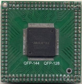
 Bild