D2-15, D2-18, D2-22) No marking: In plastic bag D: Straight CS: Short clinched Resistance tolerance L: ±15% Element (head part) diameter Inrush current limiter series Rated zero-power resistance (Ω) at 25 ℃ 5 D2 -11 L T3C Taping options T3C: Clinched taping T3D: Straight taping ■ Dimensions D T H H0
Equation 4.1, into that for the self-capacitance, Equation 5.4, gives : 6 2 2 2 2 2 C self 10 µ [fN l )p+ (α l ) e /[(2π) 300/2) A N ] L 2 2 2 = 1.13 µ f(N l p + (α l )e]/ [A NL] For lengths in mm and A in µH/N , this becomes : L C self 1.13 10 µ l f p 2/ A L 1.13 10 µ [ (α f ) / Ae] / NL 2 6.1 where
in this region of the spectrum is 2.56. Hence the average relative permittivity is: (2.56+1)/2 = 1.78 , and the asymptotic formula in that case is: C L 4ε 0 = 1.78 π (ℓ/D) D The comparison is given in the graph below, with Medhurst's adjusted data superimposed . 65 It is obvious that when the coils become
ith in th e ra n g e o f 0 to 5 9 d B m (R 41 31 A /B /C /D ) and 110 dB i to 51 dB i f D A. 11 r£ J L fT L . #. L & r M t z U n it o f re fe re n c e le v e l: d B m , d B i, d B p /rn , o r d B m V , s e le c ta b le M ark er d isp lay R eso lu tio n 0.2 dB 10 dB/DIV 0.05 dB 2 dB/DIV 8 - 3 O ct2O /89
einstellbarer Lichtgeschwindigkeit... Die zwei Dioden links und rechts haben anscheinend den SMD-Code "L05" https://www.s-manuals.com/pdf/datasheet/s/l/sl05t1%2C_sl12t1%2C_sl15t1%2C_sl24t1_on.pdf eine 5V TVS-Diode ? Zu "21Y" finde ich nur 5-pin Spannungsregler
Transistoren mit denen im Multiplex 2 Reihen a 12 LED über 12 Vorwiderstände angesprochen werden. Die L05 werden 78L05 in SOT23 sein, 2 Stuck weil einer zu warm wird. Die Software hat halt nicht für Stereo gereicht, da wurde dann 'optimiert' Christian C. schrieb im Beitrag #7812118: > sie ist trotz
Ich finde kein "LM7805cp" nur in anderer Anordnung z.B. L78M05cp .... Link zum Datasheet und Bauform bitte nennen. TO92 kann keine 1,5 A..
Chris K. schrieb im Beitrag #7463890: > Ich finde kein "LM7805cp" nur in anderer Anordnung z.B. L78M05cp > .... > > Link zum Datasheet und Bauform bitte nennen. TO92 kann keine 1,5 A.. L7805CP von ST ist in TO-220FP.
Associated gain Gass 15 Linearity dBm • 3rd order intercept pointatoutput OIP3 30 IC= 70mA, Z SZ =L0Ω • 1 dB gain compression pointatoutput OP 17 1dB Table 12 AC characteristics,V CE=3V,f =3.5GHz Parameter Symbol Values Unit Note or testcondition Min. Typ. Max. Power gain – – dB • Maximum powergain
********* ;* ;* Title : AVR ISP (Auto adr inc, 19200bps) ;* Version : 3.2 ;* Last updated : 17/Jan/05 ;* Target : AT90S2313 @ 4Mhz (orig. AT90S1200) ;* File : AVR910_2313_v3_2.asm ;* Author(s) : Ole Saether, Terje Frostad, ;* Ingar Fredriksen, Morten W. Lund ;* Haakon Skar, Paal Kastnes ;* ;See original appnote for more info. ;* ;* HISTORY ;* V3.3 05/Jan/06 (J.Samperi) Fixed bug with page mode. See note at w7: ;* ;* V3.2 17/Jan/05 (J.Samperi)Added support for newer devices supported by AVRprog 1.4 ;* Some doubtfull or non working device codes commented
is active L L H Yes L H L H H Yes L L Normal operation with H L H Yes H H auto-powerdown H H H Yes H L dsa e /ena ed Open Open H No L H H=highlevel,L=lowlevel,X=irrelevant,Z=highimpedance(off),Open=inputdisconnectedorconnected
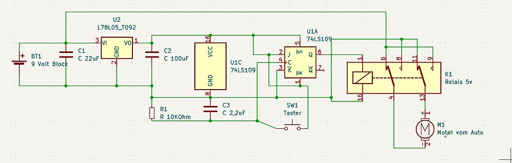
Programmende selbst ausschalten. https://www.reichelt.de/signalrelais-bistabil-2-wechsler-2a-hfd2-l-12v-p101943.html
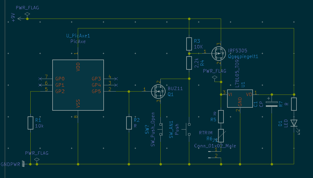
schalten, das ist ja schon fast dessen Leckstrom (250uA) und UGS(th). Nimm lieber einen BC547. Ein 78L05 weil du Strom sparen willst, der verbraucht ja schon mehr als er spart und nutzt die Batterie nicht mehr zwischen 7.5 und 5.4V, nimm MC78FC05 oder MCP1702-5.0. Ein Öffner-Taster, ugh, schwer
USB_DM 70 21 PWRKEY USB_VBUS 71 20 RESET_N C N N T K _ M L D P S T D C _ X R R A V GND 72 v S _ _ _ _ _ _ I I E 2 19 GND e N H H I I I M G M M I R 117 L 118 E 119 E 120 G 121 G 122 G 123 S 124 S 125 S 126 P127 U 128 Reserved 113 W S S S X T 115 USB_BOOT 3 2 1 0 _ T T e Reserved 114 A 129 A 130 A 131 A 132 L 133 D 134 O E135 E 136 A 137 A 138 N139 r 140 116 _ _ _ _ _ C E E N _ _ T e Reserved C C C C C 1 A I L E E B R S S S S S D W W W C C S 1 2 3 4 5 6 7 141 142 8 9 10 11 12 13 14 15 16 17 18 W A W W N N
| | | | | | -> LT1117 CST-3.3V für 1.55 € Spannungsregler in SMD-Version (7805 etc., nicht nur der 78L05) | | | | | | | -> LT1117-ADJ für 1.55€ TSic Temperatursensoren von ZMD | -> TSIC Leiterplattenbuchse Hirschmann 4mm auch in *rot* (gab es schonmal als "PB 4 RT) -> wieder als PB 4 RT erhältlich, letzte
generell Spannungsregler, LOW-DROP, SMD (DPAK, D2PAK) Spannungsregler SMD in DPAK | | | | (u.a. MC 78M05 CDTG) MCP23016 16Bit I2C I/O Expander | | | (verfügbar) MCP23S17 16Bit SPI I/O Expander (aber ohne Schmidt-triggerd Eingänge wie der 23x16) * LT-1117-CST-5 als Sot223 (adj und 3.3 gibts schon, 5 fehlt
Associated gain Gass 15 Linearity dBm • 3rd order intercept pointatoutput OIP3 30 IC= 70mA, Z SZ =L0Ω • 1 dB gain compression pointatoutput OP 17 1dB Table 12 AC characteristics,V CE=3V,f =3.5GHz Parameter Symbol Values Unit Note or testcondition Min. Typ. Max. Power gain – – dB • Maximum powergain
10.5 11.0 11.5 12.0 13.0 14.0 16.0 18.5 • LEAD WIRE CONFIGURATIONS (mm) Format A Cases 01 to 12 (1) L = 16 ± 4 S = 2.5 ± 0.5 d = 0.5 ± 0.05 Format B Cases 01 to 12 (1) L = 16 ± 4 S = 5.0 ± 1.0 d = 0.5 ± 0.05 Format C Cases 01 to 15 L = 16 ± 4 S = 5.0 ± 1.0 d = 0.5 ± 0.05 * supplied in tape format only
VCCor GND See Figure 16 25°C 2.5 V 2.6 pF capacitance BW Bandwidth R = 50 Ω, –3 dB 25°C 2.5 V 17 MHz L f = 100 kHz, see OISO OFF isolation R L 50 Ω 25°C 2.5 V –66 dB Figure 20 f = 100 kHz, XTALK Crosstalk R L 50 Ω 25°C 2.5 V –75 dB see Figure 21 Total harmonic R = 600 Ω, f = 20 Hz to THD L 25°C 2.5 V
2 2 2 D G 7 2 . C S I C T C D C N D D D D D 1 C A C 0 1 O S F O M M N E E E E E E N S 0 R V S S E L L L L L V 3 A D 4 D T S 8 2 1 V D V 3 2 0 3 8 U D 1 a R 1 2 0 0 S 9 S p R 1 D T q V 1 D C T T U b P D 1 8 V S I F A L S K 1 2 S S 1 4 u V N M R S S S N D C S S N N N N V C C C C S V 1 3 F 1 2 4 3 1 P
************** ;************************************************************************* ;* A P P L I C A T I O N N O T E F O R T H E A V R F A M I L Y ;* ;* Number : AVR000 ;* File Name : tn816def.inc ;* Title : Register/Bit Definitions for the ATtiny816 ;* Created : 2022-03-02 14:26 ;* Version :
instead of a coil inductor, the Thompson formula F = 1/(2πLC) .5 is no longer valid and the inductance L has to be replaced with a hyperbolic TAN function, X = Z tanh 2pl , with l < l /4 . As a L 0 l result, the circuit has a sharper resonance or appears to have a higher Q. Figure 11 shows the impact
tra01 b own yellow 12 transparent green 0 03 03 gr yw 18 18 tra02 g ent red 14 transparent yellow 2 05 golden n 04 04 yellow 03 grey 18 transparent red s 05 05 golden 04 yellow a 3 06 06 whitee 05 golden e 0 Ordering example: 15501 + 16270 + 1630008 + 16325 9 + 1632708 + 1692208 3 m3. Ordering example
parameter. been reached at t =p10 s.-6 1E+01 Zth j-mb / (K/W) BUK553-100A = 1E+00 0.5 0.2 0.1 1E-01 0.05 0.02 1E-02 D tp = t 0 T t 1E-03 T 1E-07 1E-05 1E-03 1E-01 1E+01 t / s Fig. 9 Example of the presentation of the transient thermal impedance as a function of the pulse time with duty factor as parameter
決定年月日 Issue Date : April 23, 2019 1. 品番 Part Number 当 社 品 番 Murata Part Number テーピング品 CSTNE16M0VH3L000R0 Taping バラ品 Bulk CSTNE16M0VH3L000B0 2. 適 用 Scope 当製品仕様書は、マイクロコンピュータ等のクロック発生回路に使用するセラミック発振子(セラロック ) ® について規定します。この用途以外にご使用の場合には事前に当社へご連絡ください。 This product specification is applied to the piezoelectric
L S 1 f0= (58) 2p L SC L ergibt sich nach Gleichung 54 zu: f = f (59) 0 C 1− L C Leff wobei f die Meßfrequenz ist. Nach der Thomsonschen Formel (58) erhält man schließlich die gesuchte Zuleitungsinduktivität
Ingo L. schrieb im Beitrag #7415274: > for ( uint8_t i = 0; i<64; i++ ){ [c] for ( uint8_t i = 0; i<=64; i++ ){ [/c] selber reingefallen :(
unsigned long long int num) { unsigned long long int res = 0; unsigned char l = N; for (unsigned char r = 0; N > r; ++ r) { if (0 != ((0x1 << r) & num)) { res |= (0x1 << l); } /* in */ -- l; } /* r */ return res; } /*
100A/µs ④ rr on Forward Turn-On Time Intrinsic turn-on time is negligible (turn-on isSdDminated by L +L ) Notes: ① Repetitive rating; pulse width limited by ③ SD ≤ -38A, di/dt ≤ -270A/µDD ≤ V(BR)DSS max. junction temperature. ( See fig. 11 ) TJ≤ 175°C ② StartingJT = 25°C, L = 1.3mH ④ Pulse width ≤ 300µs

 Bild
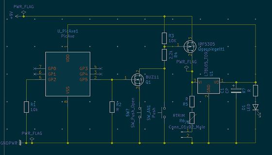
 Bild
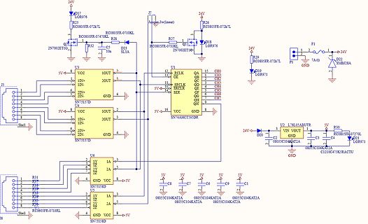
 Bild
 Bild
 Bild
 Bild

 Bild