-
Datei
Uhr_Temp.asm
= r22 .def EE_Adr = r23 .def rawlow = r24 ;Rohwert DS18B20 LSB .def rawhigh = r25 ;Rohwert DS18B20 MSB .equ DQ = 7 ;Datenleitung des Ds18B20 .equ DS_DDR = DDRC ;Port des DS18B20 .equ DS_Port = PortC .equ DS_Pin = PinC .equ LCD = PortB ;LCD-Datenport .equ
-
PDF
stb6nk60z.pdf
Min. Typ. Max. Unit g (1) Forward transconductance V DS= 8 V, D= 3 A 5 S fs C pF iss Input capacitance 905 Coss Output capacitance V DS= 25 V, f = 1 MHz, pF V = 0 115 pF Crss Reverse transfer GS 25 capacitance Coss eq2.Equivalent output V = 0, V = 0 to 480
-
PDF
stb6nk60z.pdf
Min. Typ. Max. Unit g (1) Forward transconductance V DS= 8 V, D= 3 A 5 S fs C pF iss Input capacitance 905 Coss Output capacitance V DS= 25 V, f = 1 MHz, pF V = 0 115 pF Crss Reverse transfer GS 25 capacitance Coss eq2.Equivalent output V = 0, V = 0 to 480
in „Unterschiedliche Power MOSFET kompatibel?“ · Analoge Elektronik und Schaltungstechnik ·
-
PDF
LMC7111BIM5X.pdf
3V L DS012352-25 DS012352-26 DS012352-27 Sourcing Output vs Sinking Output vs Gain and Phase vs Output Voltage Output Voltage Capacitive Load @ 3V DS012352-28 DS012352-29 DS012352-30 Gain and Phase vs Gain and
in „PIN Dioden Geiger“ · Mikrocontroller und Digitale Elektronik ·
-
PDF
LMC7111BIM5X.pdf
3V L DS012352-25 DS012352-26 DS012352-27 Sourcing Output vs Sinking Output vs Gain and Phase vs Output Voltage Output Voltage Capacitive Load @ 3V DS012352-28 DS012352-29 DS012352-30 Gain and Phase vs Gain and
in „Einbau-Vorverstärker für E-Gitarre, Ub = 3V“ · Analoge Elektronik und Schaltungstechnik ·
-
PDF
Uhr.pdf
------------------------------------------------------------- 142 ; Bufferbereich 143 ; 144 oldio: ds 1h ; Sicherung Io-Byte 145 dstbeg ds 2 ; 146 dstend ds 2 ; 147 bzaehl db 0 ; Sicherung fuer Zaehlregister (B) 148 buflaeng ds 2 ; Bufferlaenge 149 recz ds 1 ; Recordzaehler 150 ; 151 efcb: db 0 ; Schreiben
in „Suche MOPPEL Projekt in Heft oder .PDF“ · Mikrocontroller und Digitale Elektronik ·
-
PDF
ips021.pdf
Test Conditions o Rds(on) ON state resistance j = 25 C 100 130 150 T j 150 C — 220 280 mΩ Vin= 5V, ds = 1A o dss 1 Drain to source leakage current 0 0.01 25 µA Vcc = 14V, j = 2o C dss 2 Drain to source leakage current 0 0.1 50 Vcc = 40V, j = 25 C V clamp 1 Drain to source clamp voltage 1 48 54 56 d =
in „Intelligenter Schalttransistor...“ · Analoge Elektronik und Schaltungstechnik ·
-
PDF
ips021.pdf
Test Conditions o Rds(on) ON state resistance j = 25 C 100 130 150 T j 150 C — 220 280 mΩ Vin= 5V, ds = 1A o dss 1 Drain to source leakage current 0 0.01 25 µA Vcc = 14V, j = 2o C dss 2 Drain to source leakage current 0 0.1 50 Vcc = 40V, j = 25 C V clamp 1 Drain to source clamp voltage 1 48 54 56 d =
-
PDF
AN11158_Understanding_MOSFET_data_sheet_parameters__NXP.pdf
DS(on) drain-source on-state resistance GS = 10 V; D = 20 A; - 8.2 12 m T = 25C; j Dynamic characteristics Q GD gate-drain charge D = 20 A; VDS = 44 V; - 14.8 - nC VGS = 10 V; Avalanche ruggedness E
in „Flyback-Wandler Störungen auf Versorgung“ · Analoge Elektronik und Schaltungstechnik ·
-
PDF
handbuch_tx-ds575x_manual_e.pdf
cannot play any digital signals from the digital input jacks (Dolby digital, DTS, etc.). OPT1 — The TX-DS575X plays back a digital signal input 1 from the OPTICAL 1 jack. OPT2 — The TX-DS575X plays back a digital signal input DVD from the OPTICAL 2 jack. COAX1 — The TX-DS575X plays back a digital signal
in „Verstärker ONKYO TX-DS 575 funktioniert nicht mehr richtig“ · Analoge Elektronik und Schaltungstechnik ·
-
PDF
Solar-DS.pdf
loose. 1. Cover one of the battery wires with tape. That way it can't short while you are 2. Positive DS wire. working on it. 3. Negative DS wire. 4. Negative battery wire. 5. Positve battery wire. http://www.instructables.com/id/Solar-DS-quotLightquot-Redone-and-Greatly-Impr/ step 14: Unite the Panels
in „Woher Mini-Solarzellen?“ · Analoge Elektronik und Schaltungstechnik ·
-
Datei
DS10-g0120-PID.c
********** // * Datenspeicher 10 * // ******************* // Flüssigkristallanzeige LMK62R125A1 // DS18B20 NR. 13,14,15,16 an 63-10 Adresse 0x18 /************************************************************************/ /* Messstelle 3 = Spannungseingang P6.3 */ /* Messstelle 2 = Spannungseingang P6.2
in „while-Schleife vorzeitig verlassen“ · Mikrocontroller und Digitale Elektronik ·
-
PDF
RealSimGear.pdf
54 5f code:14ae 42 54 4e ds "BTN_SOFT_12" 5f 53 4f 46 54 5f code:14b4 42 54 4e ds "BTN_NAV_TOG" 5f 4e 41 56 5f 54 code:14ba 42 ?? 42h B code:14ba.1 54 ?? 54h T code:14bb 4e ?? 4Eh N code:14bb.1 5f ?? 5Fh _ Oct 15,
in „ATmega2560 hex File disassemblieren“ · Mikrocontroller und Digitale Elektronik ·
-
PDF
MCP738312.pdf
Charge Current I 90 100 110 mA PROG = 10 k REG Regulation 450 505 550 mA PROG = 2.0 kNote 1 12.5 14.5 16.5 mA PROG = 67 k TA = -5°C to +55°C Note 1: Not production tested. Ensured by design. 2005-2014 Microchip Technology Inc. DS20001984G-page 3 MCP73831/2 DC CHARACTERISTICS (CONTINUED) Electrical
in „MCP73832 Beschaltung für die Auswertung mit µC“ · Mikrocontroller und Digitale Elektronik ·
-
PDF
top2008.pdf
ATMEGA162V, ATMEGA162U, ATMEGA163, ATMEGA163L, AT90S2323, AT90LS2323, AT90S2343, AT90LS2343, ____MPU-DALLAS DS87C520, DS89C420, DS89C430, DS89C440, DS89C450, ____MPU-SST SST89C54, SST89C58, SST89F54, SST89F58, SST89E554RC, SST89E564RD, SST89V554RC, SST89V564RD, SST89E52RD, SST89E54RD, SST89E58RD, SST89E516RD,
in „[V] Top 853 Universal Programmer + 74er Tester“ · Markt ·
-
PDF
data.pdf
Parameter Min. Typ. Max. Units Test Conditions o Rds(on) ON state resistance j = 25 C 10 20 25 m V in= 5V, ds= 1A Tj= 150 C — 35 45 I Drain to source leakage current 0 0.5 25 V = 14V, T = 25 C dss1 o cc j @Tj=25 C A dss2 Drain to source leakage current 0 5 50 Vcc = 40V, j = 25 C o @Tj=25 C V clamp 1 Drain to
in „Problem mit MOSFET-Schalter“ · Analoge Elektronik und Schaltungstechnik ·
-
PDF
DS18S20_1_.pdf
GND > 1µs MASTER SAMPLES MASTER SAMPLES > 1µs 15µs 45µs 15µs LINE TYPE LEGEND BUS MASTER PULLING LOW DS18S20 PULLING LOW RESISTOR PULLUP Figure 13. Read/Write Time Slot Timing Diagram www.maximintegrated.com Maxim Integrated │ 14 DS18S20 High-Precision 1-Wire Digital Thermometer Read-Time Slots read-time
in „433Mhz RF Wireless Transmitter + Receiver“ · Mikrocontroller und Digitale Elektronik ·
-
PDF
PT4115E.pdf
TSD) protection function. The TSD China Resources Powtech (Shanghai) Limited WWW.CRPOWTECH.COM Page 14 PT4115_DS Rev EN_2.6 PT4115 30V, 1.2A Step-down High Brightness LED Driver with 5000:1 Dimming TYPICAL APPLICATION CIRCUIT Fig1 :1W application Fig 2: 3W application PT4115_DS Rev EN_2.6ech (Shanghai
in „PT4115 KSQ raucht ab. Gleichrichter nötig?“ · Analoge Elektronik und Schaltungstechnik ·
-
PDF
PT4115E_Copy.pdf
TSD) protection function. The TSD China Resources Powtech (Shanghai) Limited WWW.CRPOWTECH.COM Page 14 PT4115_DS Rev EN_2.6 PT4115 30V, 1.2A Step-down High Brightness LED Driver with 5000:1 Dimming TYPICAL APPLICATION CIRCUIT Fig1 :1W application Fig 2: 3W application PT4115_DS Rev EN_2.6ech (Shanghai
in „Driver IC für High Power LED bis max 3Euro“ · Mikrocontroller und Digitale Elektronik ·
-
PDF
AP3031.pdf
n 55 T w T = -40 C C d A 0.8 u 50 T = +25 C S A o 45 TA= +85 C 0.6 0.4 402 4 6 8 10 12 14 16 -60 -40 -20 0 20 40 60 80 100 120 140 Input Voltage (V) Temperature ( C) AP3031 5 of 13 December 2022 Document number: DS41442 Rev. 2 - 2 www.diodes.com © 2022 Copyright Diodes Incorporated. All Rights
in „Verständnisfrage Datenblatt AP3031 PMIC“ · Mikrocontroller und Digitale Elektronik ·
-
Datei
G32trust.asm
call ds:FreeLibrary loc_100016B3: ; CODE XREF: gt_CheckTrustFund+378 j ; gt_CheckTrustFund+380 j mov eax, [esp+14h] mov ecx, eax dec eax test ecx, ecx mov [esp+14h], eax jz short loc_10001703 jmp loc_10001348
in „Wer kann mir eine ASM File compelieren“ · Softwareentwicklung ·
-
 Bild
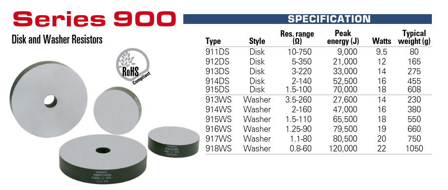
Spezifikationstabelle für Series 900 Disk und Washer Resistors
RoHS Compliant SPECIFICATION Type Style Res. range (Ω) Peak energy (J) Watts Typical weight (g) 911DS Disk 10-750 9,000 9.5 80 912DS Disk 5-350 21,000 12 165 913DS Disk 3-220 33,000 14 275 914DS Disk 2-140 52,500 16 455 915DS Disk 1.5-100 70,000 18 608 913WS Washer 3.5-260 27,600 14 230 914WS Washer
in „Neue Bauteile – kleine Relais, nicht durchbrennende LED-Serienschaltungen und Co“ · Analoge Elektronik und Schaltungstechnik · · Screenshots
-
PDF
21709c_EEPROM.pdf
which can be obtained from Microchip’s web site: www.microchip.com. 2003 Microchip Technology Inc. DS21709C-page 3 24AA02/24LC02B FIGURE 1-1: BUS TIMING DATA 5 4 2 3 SCL 7 8 9 10 6 SDA 14 IN 11 12 SDA OUT FIGURE 1-2: BUS TIMING START/STOP D4 SCL 6 7 10 SDA Start Stop DS21709C-page 4 2003 Microchip
in „EEPROM mit Infineon XC2200 ueber IIC benutzten“ · Mikrocontroller und Digitale Elektronik ·
-
PDF
21709c.pdf
which can be obtained from Microchip’s web site: www.microchip.com. 2003 Microchip Technology Inc. DS21709C-page 3 24AA02/24LC02B FIGURE 1-1: BUS TIMING DATA 5 4 2 3 SCL 7 8 9 10 6 SDA 14 IN 11 12 SDA OUT FIGURE 1-2: BUS TIMING START/STOP D4 SCL 6 7 10 SDA Start Stop DS21709C-page 4 2003 Microchip
in „24LC02B mit (scheinbar) seltsamer Adressierung“ · Mikrocontroller und Digitale Elektronik ·
-
PDF
IRF7822.pdf
5.0 6.5 mΩ V GS= 4.5V, D = 15AR on Resistance Gate Threshold Voltage V 1.0 V V = V ,I = 250µA GS(th) DS GS D Drain-Source Leakage DSS 30 V DS= 24V, VGS= 0 Current Current* 150 µA V DS= 24V, VGS= 0, Tj = 100°C Gate-Source Leakage GSS ±100 nA V GS= ±12V Current Total Gate Chg Cont FET QG 44 60 V GS.0V, I
in „Falsches Ladegerät am Notebook :-(“ · Mikrocontroller und Digitale Elektronik ·
-
PDF
usblc6-2.pdf
Mode SW1 SW2 Low Speed LS Open Closed Full Speed FS Closed Open High Speed HS Closed then open Open DS4260 - Rev 7 page 9/20 USBLC6-2 PSpice model Figure 14. T1/E1/Ethernet protection C +VCC - Tx 100nF L S U SMP75-8 DATA TRANSCEIVER +VCC C 6 Rx 100nF B U SMP75-8 2.6 PSpice model Figure 15. PSpice model
in „STM32 und USB A mit Schutz-ICs“ · Mikrocontroller und Digitale Elektronik ·
-
PDF
IPB180P04P4.pdf
Drain-source breakdown voltage V (BR)DSSV GS=0V, ID= -1mA -40 - - V Gate threshold voltage V GS(th) V DS=V GS, D =-410µA -1.2 -1.7 -2.2 V DS=-32V, V GS=0V, Zero gate voltage drain current IDSS T =25°C - -0.1 -1 µA j V DS=-32V, V GS=0V, 2) - -20 -200 T j125°C I V =-16V, V =0V Gate-source leakage current
in „wie pMOSFET für Strombegrenzung kühlen“ · Analoge Elektronik und Schaltungstechnik ·
-
PDF
spp20n60s5_eng_tds.pdf
SPP20N60S5 Cool MOS™ Power Transistor V DS 600 V Feature R DS(on) 0.19 Ω • New revolutionary high voltage technology D 20 A • Worldwide best R in TO 220 DS(on) • Ultra low gate charge PG-TO220 2 • Periodic avalanche rated • Extreme dv/dt rated
in „Mosfet defekt - kann der Ersatztyp verwendet werden?“ · Analoge Elektronik und Schaltungstechnik ·
-
PDF
RF_PICKIT.pdf
information regarding the PIC16F630/676 14-pin FLASH-based 8-bit CMOS microcontroller device specifications. PICkit™ 1 FLASH Starter Kit User’s Guide (DS40051) Consult this document for information regarding the PICkit 1 FLASH Starter Kit. ®
in „[V] Verkaufe RF PIC KIT Transmitter & Receiver Module“ · Markt ·
-
Datei
Main.c
include <stdio.h> #include <user_io.c> #include <avr/signal.h> #include <avr/interrupt.h> #include <ds18s20.h> #include <ds18s20.c> /* FCPU = 8 MHz _delay_ms = 32,77 ms _delay_us = 96,00 us*/ float temperature=0; uint8_t t1=13,t2=13,t3=10,t4=11; int main (void) { // PORTA (LED-OUT) DDRA = 0xFF; PORTA
in „float-wert umwandeln“ · Mikrocontroller und Digitale Elektronik ·
-
PDF
BSP308.pdf
Unit min. typ. max. Dynamic Characteristics Transconductance gfs 6.1 8.8 - S V ≥2*I *R , I = 3.9 A DS D DS(on)max D Input capacitance Ciss - 400 500 pF VGS = 0 V, DS = 25 V, f = 1 MHz Output capacitance Coss - 160 200 VGS = 0 V, DS = 25 V, f = 1 MHz Reverse transfer capacitance Crss - 70 90 VGS = 0 V
in „Suche Depletion Mode Fet, n-Kanal, low Rds on oder Alternative“ · Analoge Elektronik und Schaltungstechnik ·
-
PDF
EUA2005.pdf
1.0 1.5 2.0 2.5 3.0 3.5 4.0 4.5 5.0 V - Common Mode Input Voltage - V IC Figure14. Figure15. Figure16. Figure17. Figure18. Figure19. DS2005 Ver 1.1 Nov. 2006 8 EUA2005 SUPPLY RIPPLE REJECTION RATIO vs DC COMMON MODE VOLTAGE 0 -10 d - -20 t a R -30 i c j -40 e V DD.5V e -50 VDD3.6V
in „"Brainstorming" Verstärker für hochohmige Kopfhöhrer“ · Analoge Elektronik und Schaltungstechnik ·
-
PDF
_LISTE_FAMILY_CODE_V1.pdf
Family Bezeichnung CODE Bemerkung DS1820 x10 Temperatur (nicht mehr produziert) DS18B20 x28 TEMPERATUR DS18S20 x10 Temperatur DS1822 x22 Temperatur DS1920 x10 TEMPERATUR DS1985 x0B ADD ONLY DS2405 x05 Adressable_SWITCH DS2406 x12 Dual Addressable Switch Plus 1kbit Memory DS2407 x12 Dual Addressable Switch Plus 1kbit Memory DS2409 x1F MicroLAN Coupler DS2417 x27 RTC DS2422 x1C Temperature/Datalogger with 8kB Datalog Memory DS2423 x1D 4k RAM DS2430A x14 EEPROM 256BYTE DS2433
in „DS1820 DS18s20 Digital Thermometer 1-wire Beispiele ATmega8 Assembler“ · Projekte & Code ·
-
PDF
VMO1200-01F.pdf
auxiliary AC drives of TVJ 125°C 6 mA electric vehicles I V = ± 20 V;V = 0 V 1.2 µA - DC drives GSS GS DS Q g 1710 nC - power supplies Q V = 10 V;V = 50 V; I = 1000 A 396 nC gs GS DS D Q gd 1020 nC td(on) 360 ns tr inductive load 1620 ns td(off) 460 ns tf VGS= 10 V;V DS= 50 V 1020 ns E D = 1000 A; RG= 1.8
in „Impulsströme“ · Analoge Elektronik und Schaltungstechnik ·
-
PDF
VMO1200-01F.pdf
auxiliary AC drives of TVJ 125°C 6 mA electric vehicles I V = ± 20 V;V = 0 V 1.2 µA - DC drives GSS GS DS Q g 1710 nC - power supplies Q V = 10 V;V = 50 V; I = 1000 A 396 nC gs GS DS D Q gd 1020 nC td(on) 360 ns tr inductive load 1620 ns td(off) 460 ns tf VGS= 10 V;V DS= 50 V 1020 ns E D = 1000 A; RG= 1.8
in „Wie wähle ich Treiber für VMO1200-01F?“ · Mikrocontroller und Digitale Elektronik ·
-
Datei
DS18B20.c
/********** DS18B20.c *****************/ #include <16F1829.h> #include <DS18B20.h> #use delay(clock=16000000) unsigned int ds1820_present() { boolean present; output_low(DS1820_DATA); delay_us(500); output_float(DS1820
in „DS18B20 Problem“ · Mikrocontroller und Digitale Elektronik ·
-
PDF
infineon-irf1010e-mosfet.pdf
Temperature www.irf.com 3 IRF1010E 6000 20 VGS = 0V, f = 1 MHZ D = 50A C = C + C , C SHORTED iss gs gd ds V V DS= 48V 5000 Crss= Cgd ( 16 V DS= 30V C = C + C g V DS= 12V oss ds gd l F4000 Ciss o ( V c c 12 t u c3000 o p Coss o a - 8 ,2000 t C G , S 4 1000 Crss VG FOR TEST CIRCUIT 0 0 SEE FIGURE 13 1 10 100
in „DC Wandler wiederbeleben“ · Analoge Elektronik und Schaltungstechnik ·
-
PDF
REN_r01ds0145ej0102_v850e2fe4l_DST_20140421.pdf
I0VDD Internal regulator supply REG1VDD, REG1VSS ISO0 Port Supply E1VDD, E1VSS Other A0VREFP, A0VSS R01DS0145EJ0102 14 Data Sheet Chapter 3 Powersupplyspecification 3.3 Power supply groups For each of the following power supply groups the same voltage must by supplied: Table 3-2 Power supply groups Power
in „Renesas V850 (3572 (A2) FE4-L) auslesen / programmieren?“ · Mikrocontroller und Digitale Elektronik ·
-
PDF
Datenblatt_PIC12F1822.pdf
PIC12F/LF1822/PIC16F/LF1823 Data Sheet 8/14-Pin Flash Microcontrollers with nanoWatt XLP Technology 2010 Microchip TechPreliminary DS41413B Note the following details of the code protection feature on Microchip devices: • Microchip products
in „PIC12F1822-PWM Mode“ · Mikrocontroller und Digitale Elektronik ·
-
PDF
Datenblatt_PIC12F1822.pdf
PIC12F/LF1822/PIC16F/LF1823 Data Sheet 8/14-Pin Flash Microcontrollers with nanoWatt XLP Technology 2010 Microchip TechPreliminary DS41413B Note the following details of the code protection feature on Microchip devices: • Microchip products
in „Interrupt-PIC12F1822“ · Mikrocontroller und Digitale Elektronik ·
-
PDF
12F1822_1823.pdf
PIC12F/LF1822/PIC16F/LF1823 Data Sheet 8/14-Pin Flash Microcontrollers with nanoWatt XLP Technology 2010 Microchip TechPreliminary DS41413B Note the following details of the code protection feature on Microchip devices: • Microchip products
in „Auflösung PWM-Mode“ · Mikrocontroller und Digitale Elektronik ·
-
PDF
12F1822_1823.pdf
PIC12F/LF1822/PIC16F/LF1823 Data Sheet 8/14-Pin Flash Microcontrollers with nanoWatt XLP Technology 2010 Microchip TechPreliminary DS41413B Note the following details of the code protection feature on Microchip devices: • Microchip products
in „8Bits und 2Bits in eine Integer-Variable“ · Mikrocontroller und Digitale Elektronik ·
-
PDF
12F1822_1823.pdf
PIC12F/LF1822/PIC16F/LF1823 Data Sheet 8/14-Pin Flash Microcontrollers with nanoWatt XLP Technology 2010 Microchip TechPreliminary DS41413B Note the following details of the code protection feature on Microchip devices: • Microchip products
in „Timer2 auf 10bit einstellen“ · Mikrocontroller und Digitale Elektronik ·
-
PDF
PIC12FLF1822PIC16FLF1823.pdf
PIC12F/LF1822/PIC16F/LF1823 Data Sheet 8/14-Pin Flash Microcontrollers with nanoWatt XLP Technology 2010 Microchip TechPreliminary DS41413B Note the following details of the code protection feature on Microchip devices: • Microchip products
in „PIC16lf1823 General purpose I/Os mit Schmitt Trigger ?“ · Mikrocontroller und Digitale Elektronik ·
-
PDF
ZXM61N02F.pdf
Leakage IGSS 100 nA VGS=± 12V, VDS=0V Gate-Source Threshold Voltage V 0.7 V I =250 A, V = V GS(th) D DS GS Static Drain-Source On-State Resistance R 0.18 V =4.5V, I =0.93A DS(on) GS D (1) 0.24 VGS=2.7V, ID=0.47A Forward Transconductance (3) g fs 1.3 S VDS=10V,ID=0.47A DYNAMIC (3) Input Capacitance C iss
in „74LS109 Toggelt nicht“ · Mikrocontroller und Digitale Elektronik ·
-
PDF
nFET_ZXM61N02FTA.pdf
Leakage IGSS 100 nA VGS=± 12V, VDS=0V Gate-Source Threshold Voltage V 0.7 V I =250 A, V = V GS(th) D DS GS Static Drain-Source On-State Resistance R 0.18 V =4.5V, I =0.93A DS(on) GS D (1) 0.24 VGS=2.7V, ID=0.47A Forward Transconductance (3) g fs 1.3 S VDS=10V,ID=0.47A DYNAMIC (3) Input Capacitance C iss
in „ESP8266 Module mit Batterie betreiben - Strom sparen“ · Mikrocontroller und Digitale Elektronik ·
-
PDF
nFET_ZXM61N02FTA.pdf
Leakage IGSS 100 nA VGS=± 12V, VDS=0V Gate-Source Threshold Voltage V 0.7 V I =250 A, V = V GS(th) D DS GS Static Drain-Source On-State Resistance R 0.18 V =4.5V, I =0.93A DS(on) GS D (1) 0.24 VGS=2.7V, ID=0.47A Forward Transconductance (3) g fs 1.3 S VDS=10V,ID=0.47A DYNAMIC (3) Input Capacitance C iss
in „Wellenlänge Infrarot Leuchtdiode?“ · Analoge Elektronik und Schaltungstechnik ·
-
PDF
nFET_ZXM61N02FTA.pdf
Leakage IGSS 100 nA VGS=± 12V, VDS=0V Gate-Source Threshold Voltage V 0.7 V I =250 A, V = V GS(th) D DS GS Static Drain-Source On-State Resistance R 0.18 V =4.5V, I =0.93A DS(on) GS D (1) 0.24 VGS=2.7V, ID=0.47A Forward Transconductance (3) g fs 1.3 S VDS=10V,ID=0.47A DYNAMIC (3) Input Capacitance C iss
in „3.3V MOSFET ersetzen“ · Analoge Elektronik und Schaltungstechnik ·
-
PDF
nFET_ZXM61N02FTA-1.pdf
Leakage IGSS 100 nA VGS=± 12V, VDS=0V Gate-Source Threshold Voltage V 0.7 V I =250 A, V = V GS(th) D DS GS Static Drain-Source On-State Resistance R 0.18 V =4.5V, I =0.93A DS(on) GS D (1) 0.24 VGS=2.7V, ID=0.47A Forward Transconductance (3) g fs 1.3 S VDS=10V,ID=0.47A DYNAMIC (3) Input Capacitance C iss
in „ATtiny13A: ESP8266 ein- und ausschalten“ · Mikrocontroller und Digitale Elektronik ·
-
PDF
nFET_ZXM61N02FTA.pdf
Leakage IGSS 100 nA VGS=± 12V, VDS=0V Gate-Source Threshold Voltage V 0.7 V I =250 A, V = V GS(th) D DS GS Static Drain-Source On-State Resistance R 0.18 V =4.5V, I =0.93A DS(on) GS D (1) 0.24 VGS=2.7V, ID=0.47A Forward Transconductance (3) g fs 1.3 S VDS=10V,ID=0.47A DYNAMIC (3) Input Capacitance C iss
in „richtiger n-Kanal MOSFET, 3,3V soll 5V und 100mA schalten“ · Analoge Elektronik und Schaltungstechnik ·