-
PDF
Readme_130816.pdf
siehe pin_tools.py). Und i2cdetect() scannt den TWI-Bus nach empfangsbereiten Devices. Klassen - atmega_p.py Klasse für die pollenden Empfang von Daten - atmega_i.py Klasse für den Empfang von Daten via Interrupt/Hintergrundthread Module in Python3.2 mit einfacher graphischer Oberfläche (Tkinter): pin_config.py
-
 Bild
Bild
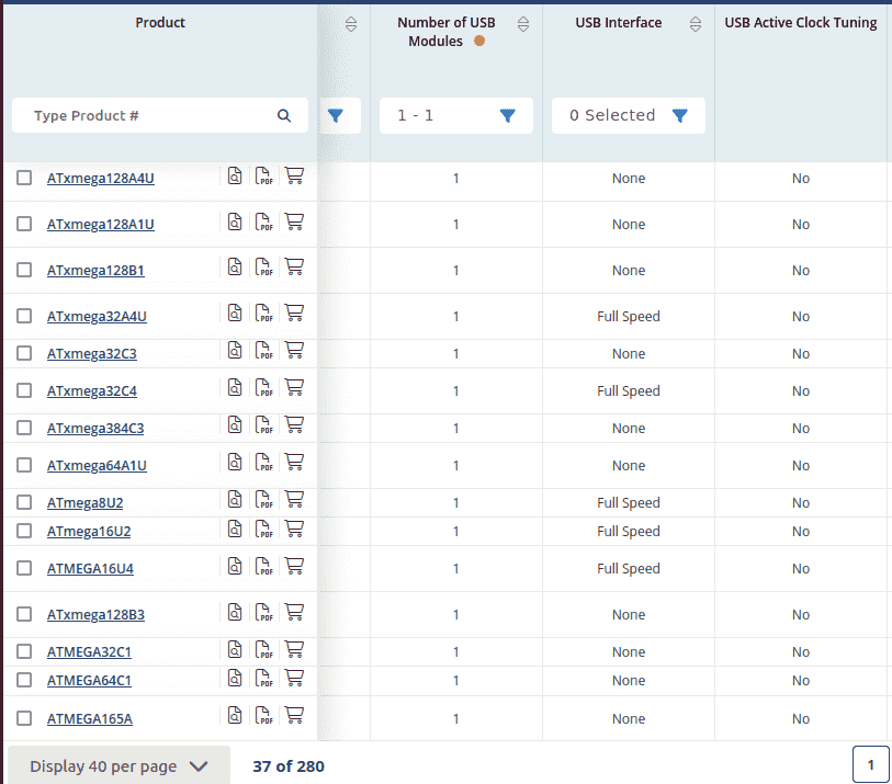
Tabelle mit Mikrocontroller-Produkten und USB-Schnittstellen
Product Number of USB Modules USB Interface USB Active Clock Tuning ATmega128A4U 1 None No ATmega128A1U 1 None No ATmega128B1 1 None No ATmega32A4U 1 Full Speed No ATmega32C3 1 None No ATmega32C4 1 Full Speed No ATmega384C3 1 None No ATmega64A1U 1 None No ATmega8U2 1 Full Speed No ATmega16U2 1 Full Speed No ATMEGA16U4 1 Full Speed No ATmega128B3 1 None No ATMEGA32C1 1 None No ATMEGA64C1 1 None No ATMEGA165A 1 None No
in „AVRs mit USB?“ · Mikrocontroller und Digitale Elektronik · · Screenshots
-
PDF
doc8012.pdf
communication or user input. Works without modification on the pin and source code compatible devices ATmega48, ATmega88 and ATmega168. 1 Introduction This application note describes how to implement sensorless commutation control of a 3-phase brushless DC (BLDC) motor with the low cost ATmega48 microcontroller
in „BLDC Regler nach AVR444 - brauche Hilfe“ · Mikrocontroller und Digitale Elektronik ·
-
Datei
avrlibc-m8-m8a-ioregs.txt
--- atmega8.S 2014-08-12 21:06:17.000000000 +0200 +++ atmega8a.S 2014-08-12 21:06:17.000000000 +0200 @@ -30,7 +30,7 @@ ARISING IN ANY WAY OUT OF THE USE OF THIS SOFTWARE, EVEN IF ADVISED OF THE POSSIBILITY OF SUCH DAMAGE. */ -/* $Id: atmega8.S 2376 2013-04-30 14:49:25Z joerg_wunsch $ */ +/* $Id: atmega8a.S 2435 2014-08-11 10:31:52Z joerg_wunsch $ */ #include <avr/version.h>
in „avr-libc 1.8.1 freigegeben“ · Mikrocontroller und Digitale Elektronik ·
-
PDF
AVR_tutorial.pdf
Programme\Atmel\AVR Tools\AvrAssembler\Appnotes\. Einige Include-Dateien heißen AT90s2313: 2313def.inc ATmega8: m8def.inc 16 ATmega16: m16def.inc ATmega32: m32def.inc ATTiny12: tn12def.inc ATTiny2313: tn2313def.inc Um sicher zu gehen, dass man die richtige Include-Datei hat, kann man diese mit einem Texteditor
in „AVR-Tutorial als PDF bzw *.doc“ · Mikrocontroller und Digitale Elektronik ·
-
PDF
Schematic_ATMEGA_CaN_L298_2020-04-23_23-39-20.pdf
TX0RTS# RX0BF# 11 L78M05 27pF 5 TX1RTS# RX1BF# 10 L78M05ABDT-TR 6 TX2RTS# 1 3 GND 12V IN OUT 5V C4 8 OSC1 GND 27pF 8MHZ 7 OSC2 C1 C8 8MHz 4 100uF 100nF VENTIL GND 18 VDD Header-Male-2.54_2x5 GND 9 VSS 5V 1 2 valveClose valveOpen 3 4 GND L298_OUT1 5 6 L298_OUT2 7 8 L298_OUT4 L298_OUT3 9 10 ATMEGA328
in „atmega328 - arduino bootloader flashen - doppelt belegte Pins“ · Platinen ·
-
PDF
ATMEGA_128_Compact_Flash.pdf
an, den ATMEGA128 und den ATMEGA128L. Der Unterschied zwischen diesen beiden Typen liegt vor allem bei den möglichen Quarzfrequenzen und Spannungen. Der ATMEGA128 kann mit Spannungen von 4.5V bis 5.5V und Quarzfrequenzen
in „CompactFlash Tutorial ?“ · Mikrocontroller und Digitale Elektronik ·
-
Datei
config.h
************************************************* */ /* MCU clock */ #define CPU_FREQ F_CPU /* * ATmega 328/328P */ #if defined(__AVR_ATmega328__) #include "config_328.h" /* * ATmega 324P/324PA/644/644P/644PA/1284/1284P */ #elif defined(__AVR_ATmega324P__) || defined(__AVR_ATmega644__) || defined(__AVR_ATmega1284__) #include "config_644.h" /* * ATmega 640/1280/2560 */ #elif defined(__AVR_ATmega640__) || defined(__AVR_ATmega1280__) || defined(__AVR_ATmega2560__) #include "config_1280.h" /* * missing or unsupported MCU */ #else #error <<< No or wrong
-
Datei
config.h
************************************************* */ /* MCU clock */ #define CPU_FREQ F_CPU /* * ATmega 328/328P */ #if defined(__AVR_ATmega328__) #include "config_328.h" /* * ATmega 324P/324PA/644/644P/644PA/1284/1284P */ #elif defined(__AVR_ATmega324P__) || defined(__AVR_ATmega644__) || defined(__AVR_ATmega1284__) #include "config_644.h" /* * ATmega 640/1280/2560 */ #elif defined(__AVR_ATmega640__) || defined(__AVR_ATmega1280__) || defined(__AVR_ATmega2560__) #include "config_1280.h" /* * missing or unsupported MCU */ #else #error <<< No or wrong
-
Datei
usiTwiSlave.c
define USI_START_VECTOR USI_START_vect #define USI_OVERFLOW_VECTOR USI_OVF_vect #elif defined( __AVR_ATmega165__ ) | \ defined( __AVR_ATmega325__ ) | \ defined( __AVR_ATmega3250__ ) | \ defined( __AVR_ATmega645__ ) | \ defined( __AVR_ATmega6450__ ) | \ defined( __AVR_ATmega329__ ) | \ defined( __AVR_ATmega3290
in „I2C Übertragungsproblem“ · Mikrocontroller und Digitale Elektronik ·
-
Datei
usiTwiSlave.c
define USI_START_VECTOR USI_START_vect #define USI_OVERFLOW_VECTOR USI_OVF_vect #elif defined( __AVR_ATmega165__ ) | \ defined( __AVR_ATmega325__ ) | \ defined( __AVR_ATmega3250__ ) | \ defined( __AVR_ATmega645__ ) | \ defined( __AVR_ATmega6450__ ) | \ defined( __AVR_ATmega329__ ) | \ defined( __AVR_ATmega3290
in „Abfrage Taster durch USI vom Slave mit zwei AVR“ · Mikrocontroller und Digitale Elektronik ·
-
Datei
usiTwiSlave.c
define USI_START_VECTOR USI_START_vect #define USI_OVERFLOW_VECTOR USI_OVF_vect #elif defined( __AVR_ATmega165__ ) | \ defined( __AVR_ATmega325__ ) | \ defined( __AVR_ATmega3250__ ) | \ defined( __AVR_ATmega645__ ) | \ defined( __AVR_ATmega6450__ ) | \ defined( __AVR_ATmega329__ ) | \ defined( __AVR_ATmega3290
in „Attiny - Arduino I2C Problem“ · Mikrocontroller und Digitale Elektronik ·
-
Datei
kompiliert_nicht_gcc910.txt
-MT atmel_start.o -D__AVR_ATmega4809__ -D__AVR_DEVICE_NAME__=atmega4809 -D__AVR_DEV_LIB_NAME__=m4809 -D NDEBUG .././atmel_start.c -mn-flash=1 -mno-skip-bug -quiet -dumpbase atmel_start.c -mmcu=avrxmega3 -auxbase-strip atmel_start.o
in „cannot read spec file 'device-specs/specs-atmega4808'“ · Mikrocontroller und Digitale Elektronik ·
-
Datei
doswrite3.c
TEST_FILE_SIZE (unsigned long)2000 * (unsigned long)1024 // test filesize 2MB #if defined (__AVR_ATmega644__) || defined (__AVR_ATmega128__) #define BUFFER_SIZE 512 #else #define BUFFER_SIZE 128 #endif void ShowDOSConfig(void); void StartTimer(void); void StopTimer(void); void ReadTestFile(char *name
in „ATmega32 + SD-Karte (Klabunde-Lib)“ · Mikrocontroller und Digitale Elektronik ·
-
Datei
Values.txt
2 BC 547B 2 BA243A 2 B40S 2 AXBA 2 AVR-ISP-10 2 ATMEGA8 2 AT90S8535J-S 2 AT90S4433P 2 AT90CAN128 2 AT8C51SND1A-PLCC84 2 AREF 2 AGND 2 ADXL322JCP-HS 2 ADUM1301 2 AD820 2 AC 24V in 2 AA_BATTERIE+CLIPS 2 AA112 2 A 2 +9V 2 9077-2 2 8 MHz 2 8.8/0.4 2 82K 2
in „[KiCad] Bibliotheksaufbau - Konzeptideen gesucht“ · Platinen ·
-
Datei
Kondensatormotor-sin_20200323b.ino
int potipluspin = 12; // atmega pin 18 Poti Pluspol int potischleiferpin = A5; // atmega pin 28 Poti Schleifer Über RC-TP int enuppin = 2; // atmega pin 4, Katode Optoled int enunpin = 3; // atmega pin 5, Katode Optoled int enzppin = 4; // atmega pin 6, Katode Optoled int upin = 9; // atmega pin 15, Anode Optoled int zpin = 10; // atmega pin 16, Anode Optoled int enznpin = 7; // atmega pin 13, Katode Optoled int relaispin = 8; // atmega pin
in „Arduino Kondensatormotor Drehzahlsteuerung“ · Analoge Elektronik und Schaltungstechnik ·
-
PDF
AVR-C-Tutorial.pdf
_t i16; struct { uint8_t i8l; uint8_t i8h; }; } convert16to8; ... convert16to8 baud; baud.i16 = F_CPU / (UART_BAUD_RATE * 16L) -1; UBRRH = baud.i8h; UBRRL = baud.i8l; ... Bei einigen AVR-Typen (z.B. ATmega8) teilen sich UBRRH
in „AVR-C-Tutorial“ · Mikrocontroller und Digitale Elektronik ·
-
Datei
TWI_2.componentinfo.xml
anyType> <d4p1:anyType i:type="FileInfo"> <AbsolutePath>G:/AVR Studio\7.0\Build1188\7.0\Packs\atmel\ATmega_DFP\1.2.150\avrasm\inc\m88padef.inc</AbsolutePath> <Attribute></Attribute> <Category>header</Category> <Condition>AVRASM</Condition> <FileContentHash>ou0dON1uozftNk3c1P0V8w==</FileContentHash> <FileVersion
in „AVR8ASM TWI Interrupt“ · Mikrocontroller und Digitale Elektronik ·
-
PDF
IQP_500_GSM.pdf
Bereitstellung der Anschlüsse, die für die Bildaufnahme mit der IQP 500 benötigt werden. Der darauf verbaute Atmega8 übernimmt die informationstechnische Verarbeitung der Bilddaten. Das bedeutet, dass der Atmega8 die Kamera über seine serielle Schnittstelle (RXD und TXD) anspricht. Da die IQP 500 über die Möglichkeit
in „IQP 500 GSM Bildübertragung Tonerätzverfahren“ · Projekte & Code ·
-
PDF
305000074A_radino_nRF8001.pdf
for more information. Arduino Micro Section common to all radino modules HID 15 GPIOs Keyboard I²C ATmega32U4 USB HID Mouse UART UART SPI MISO,MOSI,SCK Arduino Pins that are reserved for radio communication: IO8,IO9,D4,D7,A4 nRF8001 Radio Section – Bluetooth Low Energy In-Circuit GmbH Boltenhagener Str
-
Datei
RFM01.c
**************** Beispiel für RFM01-Funkmodul (Empfang) IAR Embedded Workbench IDE, C Prozessor: ATMEGA8 Frequenz: 434MHz Datenrate: 4.8kbps Diese Programm stellt eine kurze Testroutine für den ATMEGA8 in Verbindung mit einem externen 8MHz Quarz, einem RFM01-Funkmodul, und dem Pollin Electronic Funk-AVR-Evaluations-Board
in „Funkmodule von Pollin“ · Mikrocontroller und Digitale Elektronik ·
-
Datei
Devices.txt
3 BD243 3 BC556 3 BC327_SMD 3 BC327-25 3 BAT19 3 BAS40-04 3 BAS15 3 ATMEGA644A 3 AT90S8515P 3 AT90S4433P 3 AT8C51SND1A-PLCC84 3 AD1857 3 AB9V 3 9450-1 3 93LC46SM 3 90G-2 3 87758-1016 3 78L05Z 3 74HCT373N 3 74HCT244N 3 74HCT125D 3 74AC32N 3 74AC14D 3 733989-55 3 733980-62
in „[KiCad] Bibliotheksaufbau - Konzeptideen gesucht“ · Platinen ·
-
Datei
SPIsourceATmega.txt
; Schaltung : SPI: MOSI, MISO, SCK ATMega8 zu ATTinys lt. Datenblatt ; ATMega8 - ATTiny2313 ; C1 - B0 ; C2 - B0 ; C3 - B1 ; C0: PIN für Taster ; C4: PORT für LED ;------------------------------------------------------------------------- ; Prozessor : ATmega8 ; Takt : 3686400 Hz ; Sprache : Assembler (GNU) ; Datum : 13.5.2012 ; Version : 1.0 ; Autor : U.S. ;------------------------------------------------------------------------- ; ; Registerfestlegungen
in „SPI Kopplung von ATmega8 und ATtiny 2313“ · Projekte & Code ·
-
Datei
pins.h
#ifndef _PINS_H_ #define _PINS_H_ #define I2C_RTC #if defined(__AVR_ATmega328P__) //LCD5110 myGLCD(NOK_CLK,NOK_DIN,NOK_DC,NOK_RST,NOK_CE); #define TIMSKx TIMSK1 #define OCIExA OCIE1A #define TIMERx_COMPA_vect TIMER1_COMPA_vect // ATmega #define TCCRxA TCCR1A #define COMxA0
in „ATmega328P mit mehr Pins“ · Mikrocontroller und Digitale Elektronik ·
-
Datei
Kondensatormotor-sin_20200323c.ino
int potipluspin = 12; // atmega pin 18 Poti Pluspol int potischleiferpin = A5; // atmega pin 28 Poti Schleifer Über RC-TP int enuppin = 2; // atmega pin 4, Katode Optoled int enunpin = 3; // atmega pin 5, Katode Optoled int enzppin = 4; // atmega pin 6, Katode Optoled int upin = 9; // atmega pin 15, Anode Optoled int zpin = 10; // atmega pin 16, Anode Optoled int enznpin = 7; // atmega pin 13, Katode Optoled int relaispin = 8; // atmega pin
in „Arduino Kondensatormotor Drehzahlsteuerung“ · Analoge Elektronik und Schaltungstechnik ·
-
Datei
config.c
0-4 // ADC_DDR&=~ADC_PINs; // ADC_PORT&=~ADC_PINs; } void Timer_Conf()//1ms { #if defined(__AVR_ATmega8__) //Timer0 TCCR0 = (1<<CS01);// |(1<<CS00);// :8 TIMSK |= (1<<TOIE0);//IRQ //timer1 /Capture (1<<ICNC1) || (1<<CS10) TCCR1A=0; TCCR1B = (1<<ICES1) | (1<<CS11);//Capture noise canceler, Capture edge
in „optimize Os / O0“ · Mikrocontroller und Digitale Elektronik ·
-
PDF
techb_myavr_board_20.pdf
Beschreibung myAVR myAVR Board 2.0 USB • Lern- und Experimentierboard für ATMEL Mikrocontroller (ATmega8/48/88/168) • Mit Controller und typischen Ein- und Ausgabegeräten (Taster, LEDs, usw.) • Material: FR4, 1,5 mm; 0.35 µm Cu • Leiterplatte gebohrt, verzinnt, Industriefertigung, robust, bedruckt •
in „Probleme mit rjmp beim AVR Atmega 8L“ · Mikrocontroller und Digitale Elektronik ·
-
PDF
y3urefmanual_g.pdf
+ Display TX_EN 16 15 KEYS AD7 14 13 AD6 AD5 12 11 AD4 AD3 10 9 AD2 AD1 8 7 AD0 LCD_E (E) 6 5 A1 (R/W) A0 (RS) 4 3 V0 (VEE) VCC 2 1 GND J2 Version 1.00,4/5/2004 Seite 8 von 13 Yampp-3U Bauanleitung Inhalt 4.2 Graphic LCD Anleitung zum installieren eines Nokia Graphik LCD´s
in „[V] Yampp3-USB“ · Markt ·
-
Datei
avrdude_C.txt
MERCHANTABILITY or FITNESS FOR A PARTICULAR PURPOSE. Size before: AVR Memory Usage ---------------- Device: atmega8 Program: 104 bytes (1.3% Full) (.text + .data + .bootloader) Data: 0 bytes (0.0% Full) (.data + .bss + .noinit) Compiling C: main.c avr-gcc -c -mmcu=atmega8 -I. -gdwarf-2 -DF_CPU=16000000UL -Os -funsigned-char
in „C++ mit AVR-Dude“ · Mikrocontroller und Digitale Elektronik ·
-
PDF
BabyController_B328.pdf
Zwei Motortreiber mit jeweils ca. 1 A Dauerleitung (max. 3 A peak) • Programmierbarer 20MHz Atmel ATmega328P AVR Mikrocontroller (32 KB Flash, 2 KB RAM, 1 KB EEPROM) • 18 user I/O lines, 16 davon digital und 8 auch analog verwendbar • eine programmierbare LED auf dem Board • Power LED • Ein Potentiometer
in „Baby Orangutan b-328“ · Mikrocontroller und Digitale Elektronik ·
-
PDF
PWM_Controller_Manual_ohne_EEPROM.pdf
Variable Auflösung 2-16 ● 186 Byte SRAM für eigene Datenspeicherung PWM- Controller Pinout AVR ATMEL ATMEGA 8 8-Bit µController Pin Function 1 Reset 2-6, 11-19, 23-26 PWM- Outputs 22, 8 0V- GND 21, 20, 7 VCC(3-5V) 9 Clock In 10 Clock Out 9,10 Crystal, or Ceramic Resonator 27 SDA- Serial Data, TWI or IIC-
in „18- Kanal PWM Controller TWI(IIC)Interface FW. V.3“ · Projekte & Code ·
-
Datei
main.c
*/; //* : Setup RS232 = 9600,N,8,1 */; //***************************************************/; //* CodeVisionAVR Complier Option Setting */; //* Chip type : ATmega128 */; //* Program type : Application */; //* Clock frequency : 16.000000
in „GPS + Mega128 + VERZWEIFLUNG“ · Mikrocontroller und Digitale Elektronik ·
-
Datei
uart.h
circular buffers Author: Peter Fleury <pfleury@gmx.ch> http://jump.to/fleury File: $Id: uart.h,v 1.8.2.1 2007/07/01 11:14:38 peter Exp $ Software: AVR-GCC 4.1, AVR Libc 1.4 Hardware: any AVR with built-in UART, tested on AT90S8515 & ATmega8 at 4 Mhz License: GNU General Public License Usage: see Doxygen
in „Heizungssteuerung mit ATMEGA 32“ · Mikrocontroller und Digitale Elektronik ·
-
Datei
uart.h
circular buffers Author: Peter Fleury <pfleury@gmx.ch> http://jump.to/fleury File: $Id: uart.h,v 1.8.2.1 2007/07/01 11:14:38 peter Exp $ Software: AVR-GCC 4.1, AVR Libc 1.4 Hardware: any AVR with built-in UART, tested on AT90S8515 & ATmega8 at 4 Mhz License: GNU General Public License Usage: see Doxygen
in „Float via UART an PC senden“ · Mikrocontroller und Digitale Elektronik ·
-
Datei
main.c
project. Compiler: avr-gcc (WinAVR 20060421) Based on Sensirion sample code app note, rev. 2.05 MCU: ATmega8, 4MHz crystal, Vcc = 5V (important for SHT11 calculations) sensor: SHT11, DATA with external 10k pullup connected to PD4, SCK connected to PD3 MCU <-> PC: UART HFUSE/LFUSE: 0xC9/0x9F */ #include "
in „Unabhängiger Timer gesucht“ · Mikrocontroller und Digitale Elektronik ·
-
PDF
AVR_ASM_Tutorial.pdf
Benötigte Ausrüstung - www.mikrocontroller.net dieser Größe an den gleichen Positionen die Pins Nr. 1, 7, 8 und 14 wären). PD0-PD7 und PB0-PB5 sind die IO-Ports des Mikrocontrollers. Hier können Bauteile wie LEDs, Taster oder LCDs angeschlossen werden. Der Port C (PC0-PC5) spielt beim AT90S4433/Atmega8 eine
in „ASM Tutorial jetzt als PDF“ · Mikrocontroller und Digitale Elektronik ·
-
Datei
uart.h
http://jump.to/fleury Fiddled around with by: jaseg CAUTION! THIS FILE CURRENTLY ONLY WORKS WITH ATMega328p and similar devices because only for these I was keen to change the signal names to proper interrupt vectors File: $Id: uart.h,v 1.8.2.1 2007/07/01 11:14:38 peter Exp $ Software: AVR-GCC 4.1, AVR Libc 1.4 Hardware: any AVR with built-in UART, tested on AT90S8515 & ATmega8 at 4 Mhz License: GNU General Public License Usage: see Doxygen manual LICENSE: Copyright (C) 2006 Peter Fleury This program is free software; you can redistribute it and/or modify it under the terms
in „Inkonsistentes Verhalten einfachem avr-gcc-codes“ · Mikrocontroller und Digitale Elektronik ·
-
PDF
avr-jtag.pdf
programming, real time emulation and taken from target debugging for AVR microcontrollers JTAG interface (ATmega16, ATmega32, ATMega323, Programming: ATmega162, ATmega169, ATmega128). AVR- To work with AVR-JTAG you need target board JTAG have: JTAG 10 pin connector (Atmel with JTAG connector (for instance Olimex’s layout), status LED, RS232 connector AVR-M16 + AVR-P40B-P8535-8Mhz) and AVR-JTAG allows access to all the powerful AVRSTUDIO software ( you can download from features of the AVR microcontroller. All AVR http://www.avrfreaks.net in Tools section). resources can be
in „JTAG empfehlenswert?“ · Mikrocontroller und Digitale Elektronik ·
-
PDF
avr-jtag.pdf
programming, real time emulation and taken from target debugging for AVR microcontrollers JTAG interface (ATmega16, ATmega32, ATMega323, Programming: ATmega162, ATmega169, ATmega128). AVR- To work with AVR-JTAG you need target board JTAG have: JTAG 10 pin connector (Atmel with JTAG connector (for instance Olimex’s layout), status LED, RS232 connector AVR-M16 + AVR-P40B-P8535-8Mhz) and AVR-JTAG allows access to all the powerful AVRSTUDIO software ( you can download from features of the AVR microcontroller. All AVR http://www.avrfreaks.net in Tools section). resources can be
in „Anschluss JTAG am PC“ · Mikrocontroller und Digitale Elektronik ·
-
Datei
iomxx0_1.h
_SFR_MEM16(0x88) #define OCR1AL _SFR_MEM8(0x88) #define OCR1AH _SFR_MEM8(0x89) /* Combine OCR1BL and OCR1BH */ #define OCR1B _SFR_MEM16(0x8A) #define OCR1BL _SFR_MEM8(0x8A) #define OCR1BH _SFR_MEM8(0x8B) /* Combine OCR1CL and OCR1CH */ #define OCR1C _SFR_MEM16(0x8C) #define OCR1CL _SFR_MEM8(0x8C) #define OCR1CH _SFR_MEM8(0x8D) /* Reserved [0x8E..0x8F] */ #define TCCR3A _SFR_MEM8(0x90) #define COM3A1 7 #define COM3A0 6 #define COM3B1 5 #define COM3B0 4 #define
in „Tasterverarbeitung mit dem ARDUINO“ · Mikrocontroller und Digitale Elektronik ·
-
Datei
rs232-baudrate.c
INSTALL_INTERRUPT_HANDLER() ///////////////////////////// Functions //////////////////////////////////// #if defined(ATMEGA168) || defined(ATMEGA128) || defined(AT90CAN128) uint32_t rs232CalculateBaudrate(uint16_t ubrr, uint8_t ps) { return (MAIN_CLK * pwr(2, ps) / (16 * (ubrr + 1))); } uint16_t rs232CalculateUBBR(uint32_t br, uint8_t ps) { return (MAIN_CLK * pwr(2, ps) / (16 * br)) - 1; } #endif uint32_t rs232GetBaudrate(uint8_t uInstId) { if((uInstId < 1) || (uInstId > 2)) return 0; return g_uRs232Baudrate[uInstId - 1]; } bool
in „AVR TWI Master und Slave Funtionen in C“ · Projekte & Code ·
-
 Bild
Bild
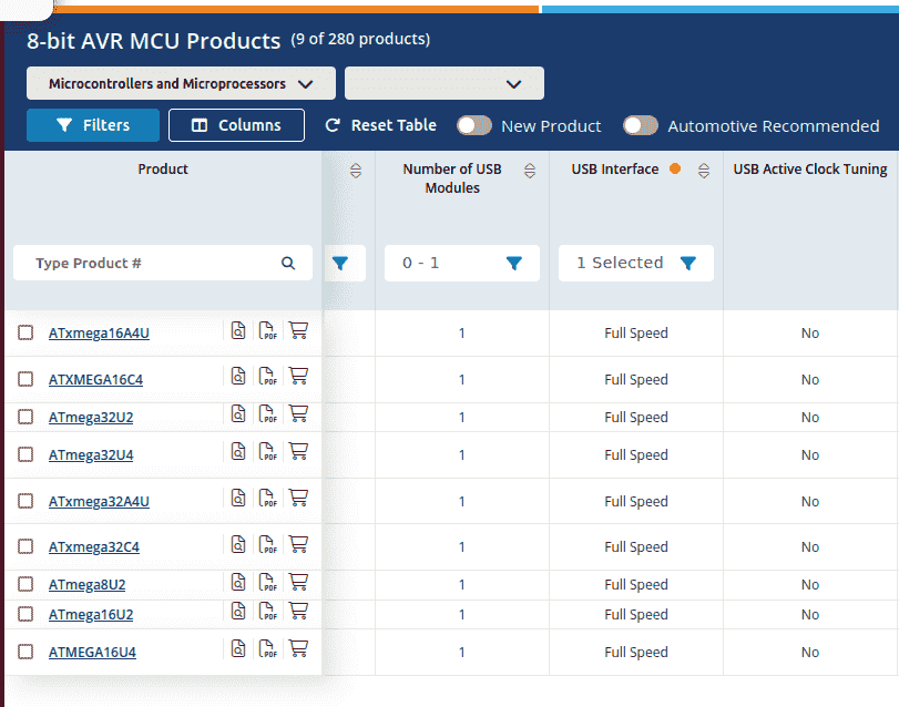
Produktliste von 8-bit AVR Mikrocontrollern
8-bit AVR MCU Products (9 of 280 products) Microcontrollers and Microprocessors Filters Columns Reset Table New Product Automotive Recommended Product Number of USB Modules USB Interface USB Active Clock Tuning Type Product # 0 - 1 1 Selected ATxmega16A4U ATXMEGA16C4 ATmega32U2 ATmega32U4 ATxmega32A4U ATxmega32C4 ATmega8U2 ATmega16U2 ATMEGA16U4 Full Speed No
in „AVRs mit USB?“ · Mikrocontroller und Digitale Elektronik · · Screenshots
-
Datei
V1.5_Slave_6.12..txt
----------------------------------------------------------------------------------- ; Funktion : ATMega8 ist SPI-Master; wählt durch SoftwareSlaveSelect einen der ATTinys ; als Slave aus (PIN B0), dieser antwortet über Port B1; dadurch kontrollierte ; Datenübertragung per SPI ; Format der Datenübertragung
in „SPI Kopplung von ATmega8 und ATtiny 2313“ · Projekte & Code ·
-
Datei
Sinus_Kondensatormotor_20200321f.ino
int potipluspin = 12; // atmega pin 18 Poti Pluspol int potischleiferpin = A5; // atmega pin 28 Poti Schleifer Über RC-TP int enuppin = 2; // atmega pin 4, Katode Optoled int enunpin = 3; // atmega pin 5, Katode Optoled int enzppin = 4; // atmega pin 6, Katode Optoled int upin = 9; // atmega pin 15, Anode Optoled int zpin = 10; // atmega pin 16, Anode Optoled int enznpin = 7; // atmega pin 13, Katode Optoled int relaispin = 8; // atmega pin
in „Arduino Kondensatormotor Drehzahlsteuerung“ · Analoge Elektronik und Schaltungstechnik ·
-
PDF
AVR-ASM-Tutorial_16_05_08_v3.pdf
Programme\Atmel\AVR Tools\AvrAssembler\Appnotes\. Einige Include-Dateien heißen AT90s2313: 2313def.inc ATmega8: m8def.inc ATmega16: m16def.inc ATmega32: m32def.inc ATTiny12: tn12def.inc ATTiny2313: tn2313def.inc Um sicher zu gehen, dass man die richtige Include-Datei hat, kann man diese mit einem Texteditor
in „AVR-ASM-Tutorial: PDF 16.5.08“ · www.mikrocontroller.net ·
-
Datei
fboot21-atmega1281.diff
if defined F_CPU +.equ XTAL = F_CPU ; defined elsewhere (eg Makefile) +#else .equ XTAL = 8000000 ; 8MHz, not critical +#endif + .equ BootDelay = XTAL / 3 ; 0.33s ;------------------------------ select UART mode ------------------------- diff -urN -x '*~' fboot21-orig/bootload/Makefile fboot21-atmega1281
in „Z180-Stamp Modul“ · Mikrocontroller und Digitale Elektronik ·
-
Datei
RTC.c
the use of I2C RTC (Real Time Clock) (DS1307). Here the DS1307 RTC Module is connected with an AVR ATmega8 MCU by I2C Serial Bus. This program reads time from the DS1307 and displays it in 16x2 LCD Module. The system also has two buttons for user interaction. The 3 buttons are 1)MENU/Enter/Move selection
in „LCD zeigt nur die hälfte an“ · Mikrocontroller und Digitale Elektronik ·
-
PDF
Dokumentation_MBHATM128-0206.pdf
Fehlfunktionen oder Kurzschlüssen führen. Ausstattung: Hardware-Eigenschaften und Ausstattung • ATmega128 AVR Mikrocontroller von Atmel • 16Mhz Quarz / Prozessortakt • 32,768Khz Quarz / RTC • 128Kbyte Flash Programmspeicher • 4 Kbytes EEPROM/ nichtflüchtiger Datenspeicher • 4 Kbytes SRAM • 2 x 8Bit
in „atmega128 modul“ · Markt ·
-
Datei
rfm70.h
/********************************************************* Title: RFM70 definitions based on ATMega Current version: v1.0 Function: RFM70 2.4GHz Module processor: ATMega16 Clock: 8M internal 64ckl startup Author: HopeRF(18.06.10)// edited (13.09.11) TB ********************************************
in „RFM70 und ATMega16 benötige Hilfe!!“ · Mikrocontroller und Digitale Elektronik ·
-
Datei
GSM_GPS_Shield_Mega.cpp
/* GSM_GPS_Shield_Mega.cpp - Libary for using the GSM and GPS-Modul on the GSM/GPRS/GPS-Shield Rev.8 Included Functions Version: 1.5.0 Date: 10.04.2013 Company: antrax Datentechnik GmbH Uses with: Arduino Mega2560 (ATmega2560) */ #if defined(ARDUINO) && ARDUINO >= 100 // Choose Arduino.h for IDE 1.0
in „GPS - Shield von Antrax mit 10hz betreiben [Arduino Mega]“ · Mikrocontroller und Digitale Elektronik ·