using grease. The ƒ oxide layer in a few seconds). Immediately prior to assembly, newer synthetic base greases show far less tendency to ‰ it is a good practice to polish the mounting area with No. migrate or creep than those made with a silicone oil base. • 000 steel wool, followed by an acetone or
Management Power Semiconductor Applications Philips Semiconductors Ptotmax / W 100 90 80 70 60 47.5 50 40 30 20 10 0 0 20 40 60 80 100 120 140 160 180 Tmb / C Fig. 3 Example of the determination of maximum power dissipation Fig. 2 Maximum d.c. power dissipation in a transistor as a function of the mounting-base
DC input coupling is selected. Check that input attenuator CH II is in 5mV/div setting. Set time base switch to 0.5ms/div. Set amplitude calibrator to 1kHz and connect a 2:1 pre-attenuator via 50Ω cable to input of CH II. Set calibrator output voltage to 80mVpp (40mVpp at the 2:1 pre-attenuator output
Turm die Blitze von den Häusern wegzieht. Nebenbei wird auch die Feldstärke Funkstrahlung reduziert. 40m oder mehr bei Häusern mit maximal 10-12m Höhe im Nahbereich sind gute Werte. Während des Blitzeinschlages gibt es im Boden eine Schrittspannung, die Elektronik zerstören kann. Besonders tritt das
natürlich Nebenzipfel. In einem Krankenhaus läuft ein DECT-System, also eine Anlage mit vielen Basen, wo man überall im Haus telefonieren und das Gespräch beliebig mitnehmen kann. Irgendwann beklagte sich der Kunde über Gesprächsabbrüche im Obergeschoss eines Gebäudeteils. Nach langer Stocherei
ist ganz schön schnell. Die Frequenz ist also 400kHz bzw. 2,5µs Pulsdauer. Das sind dann bei 16MHz 40 Takte je Puls. Das wird in C tricky, da sollte man wohl Assembler nehmen. Für Interruptgedöns ist auch keine Zeit mehr, da geht nur Polling.
Peter D. schrieb im Beitrag #7428119: > Das sind dann bei 16MHz 40 Takte je Puls. Das wird in C tricky, da > sollte man wohl Assembler nehmen. Wie erwähnt, ein RP2040 macht das ganz locker mit einer Schrittfrequenz > 100 MHz. Entsprechend konfiguriert werden vier
Fritzing-Kindergartenwimmelbilder auf Steckbretter als "Schaltpläne" verkauft. Und ja, auch ich habe seit 40 Jahren ein Vero-Steckbrett, das immer noch hervorragende Kontakte hat.
brauche. Für mehr Strom habe ich eines, das 25A kann, aber nur so um 12V herum. Das hat mir in meinen 40 Jahren Bastlerleben immer gereicht.
Absolute Maximum Rating System (IEC 134). SYMBOL PARAMETER CONDITIONS MIN. MAX. UNIT V collector-base voltage open emitter − 50 V CBO VCEO collector-emitter voltage open base − 45 V VEBO emitter-base voltage open collector − 5 V C collector current (DC) − 500 mA CM peak collector current − 1 A I peak
keine Potentialtrennung hat, wäre ich hier skeptisch. EDIT: https://kb.shelly.cloud/knowledge-base/shelly-1pm#Shelly1PM(SHSW-PM)-Supportedloadtypes Supported load types Resistive (incandescent bulbs, heating devices) Capacitive (capacitor banks, electronic equipment, motor start
Mit einem Kühlschrank hat man schon vor 40 Jahren die ersten EMV-Tests gemacht. Die primitiven Kompressormodelle mit simplen Schalter sind berüchtigt.
but LDD / STD The Y / Z + q addressing mode is more efficient. LDD / STD mode addressing based on a base address, we can set the Y / Z to The base address of the data in the RAM can be executed in one cycle by using the Y / Z + q addressing mode of the LDD / STD instruction. And access the data, and automatically
Vielleicht könnte man hier was mit LIN (Local Interconnect Network) machen. LIN ist allerdings nur bis zu 40m (bei 19.2 Kbit/s) spezifiziert. LIN-Transceiver sind sehr preisgünstig und werden mit UART angesteuert.
Victoria J. schrieb im Beitrag #7422080: > Am elegantesten finde ich aber die Variante 10BASE-T1L PoDL und die > Daten direkt ins Netzwerk einbinden zu können. 10BASE-T1L ist eine Punkt-zu-Punkt-Verbindung. Dafür brauchst Du eine Sterntopologie und einen Switch im Sternpunkt. 10BASE-T1S
isrHandler()': /Volumes/mydocs/PlatformIO/Projects/ESP32_RTOS_ISR_class/src/esp32_gpio_interrupt.cpp:40:(.iram1.28[Button::isrHandlerWrapper(void*)]+0x3): dangerous relocation: l32r: literal placed after use: .literal._ZN6Button17isrHandlerWrapperEPv [/c] aus. Und da steh ich wieder am Anfang.
48-pin SSOP package · Built-in time base generator and WDT HT1621B: 48-pin DIP/SSOP/LQFP package · Time base or WDT overflow output HT1621D: 28-pin SKDIP package · 8 kinds of time base/WDT clock sources HT1621G: Gold bumped chip · 32´4 LCD
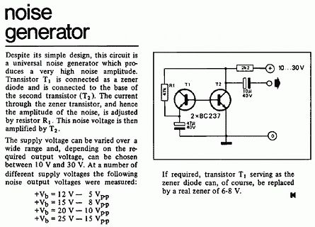
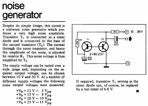
a very high noise amplitude. Transistor T1 is connected as a zener diode and is connected to the base of the second transistor (T2). The current through the zener transistor, and hence the amplitude of the noise, is adjusted by resistor R1. This noise voltage is then amplified by T2.
The supply voltage
−40°C ≤ TJ≤ 8.75 125°C VIN= 5 V 15 VOUT (MIN) Minimum Output Voltage Under Load V VIN= 2.7 V 5 −40°C ≤ TJ≤ 3.75 125°C R L 15 Ω X Option(3) VIN= 3.3 V 6.5 −40°C ≤ T ≤ J 5 125°C V = 5 V 10 IN V = 2.7 V 5 IN −40°C ≤ TJ≤ 125°C 4 R L 15 Ω(3) VIN= 3.3 V 7 Y Option −40°C ≤ TJ≤ 125°C 5.5 VIN= 5 V 10 TJ= 25°C 1.8 2 (4) SW Switch Current Limit See −40°C ≤ TJ≤ 1.4 A 125°C TJ= 25°C 260 400 ISW = 100 mA Vin = 5 V −40°
to override this guess. Note that the printed output of smartctl displays most numerical values in base 10 (decimal), but some values are displayed in base 16 (hexadeci- mal). To distinguish them, the base 16 values are always displayed with a leading "0x", for example: "0xff". This man page follows the
Thermal Characteristics Parameter Symbol Typ Max Units Maximum Junction-to-Ambient A t ≤ 10s A D RθJA 31 40 °C/W Maximum Junction-to-Ambient Steady-State 59 75 °C/W Maximum Junction-to-Lead Steady-State RθJL 16 24 °C/W www.umw-ic.com 1 UTD Semiconductor Co.,Limited R U M W AO4459 P-Channel MOSFET Electrical
Überspannungsableiter würde ich vermeiden Man möchte ja eine möglichst kleine Vorwärtsspannung - Die BAS40 hat gerade mal 200nA Leckstrom bei 75°C und 10V. Das wären bei 10k Eingangswiderstand 2mV Offset. Ich denke das kann man bei einen 12Bit ADC mit einer Referenzspannung von 4096mV vernachlässigen.
29 volts and does not require a regulated • Automobile clocks supply. The MM5316 is packaged in a 40-lead dual • Stopwatches in-line package. • Industrial clocks • Military clocks features • Portable clocks • 50 or 60 Hz operation • Photography timers • Single power supply • Industrial timers • Low
beide Abkürzzungen sind aus dem Englischen ce : collector - emitter cb : collector - base
Frido J. schrieb im Beitrag #7407326: > Also gut: Das Panel hat 25 Watt. Hänge ich ein 40 V-Netzteil mit PWM > dran dann muß das 625 mA Strombegrenzung bzw. weniger haben, oder? Bei den 40 V wärst du im Grenzbereich des Transistors. Vom Foto der Platine her ist gar nicht klar, was
Force : 1000gf maximum. Stroke : 1.0mm. Operation Temperature : -20°C to +70°C. Storage Temperature : -40°C to +85°C. Vibration Test : MIL-STD-202F METHOD 201A. Frequency : 10 - 55 - 10Hz/1 minute. Directions : X, Y, Z, three mutually perpendicular directions. Time : 2 hours each direction. High reliability
as transistors manufactured by IBM. For example, the leftmost type 51 above is date code 1957 week 40 and is identifiable as an IBM device based on the unique oval case shape and “two-hole” bottom header construction. The three next type 51 transistors, with date codes in 1956, are likely Sylvania devices
CES Collector-emitter volBE= 0)V 700 V V CEO Collector-emitter voBtage (I = 0) 400 V V EBO Emitter-base voltCge (IB= 0, I =P0.75 A, t < 10 µsV(BR)EBO V C Collector current 1.5 A IIM Base currentak curPent (t < 5 ms) 0.75 s A IBM Base peak currenP (t < 5 ms) 1.5 c t ( A PTOT Total dissipatioc at T = 25 °C d40 W TSTG Storage temperature ro-55 to 150 °C TJ Max. operating junction temperature e P 150 °C le t s o O b ) - t( s u c o d P r te o le b s O 2/8 Doc ID 14182 Rev 2 ST13003D-K Electrical characteristics
: 3762439A_ Y59 Base Material: FR-4 Material Type: FR4-Standard TG 135-140 Surface Finish: LeadFree HASL Leiterbahnen: Kupfer Lagen: 2 Bauteile: (List der Bauteile für hier entfernt)
Michael schrieb im Beitrag #7443998: > Wenn Du 40-50 Pakete / Jahr von JLCPCB bekommst, es im wesentlichen > immer die gleiche Ware ist, also bestücke PCBs, dann frage ich mich > warum Du bei einem eindeutig gewerblichen Bedarf immer wieder bei JLCPCB
voltage V CELL= 3.2 – 4.6 V ±25 mV accuracy 0°C to 60°C V CELL= 2.0 – 5.0 V ±35 V CELL= 3.6 – 4.3 V –40 40 ADC cell voltage V CELL= 3.2 – 4.6 V –40 40 accuracy –40°C to 85°C V CELL= 2.0 – 5.0 V –50 50 16-BIT CC FOR PACK CURRENT MEASUREMENT CC CC input voltage range –200 200 mV RANGE CC FSR CC full scale
Unkrautvernichter gewesen sein, ne ganz ähnliche Wirkung gehabt haben. Das muss aber schon an die 40 JAhre her sein, dass es das zu kaufen gab. Das sind aber alles ganz theoretische Erkenntnisse, praktisch damit rumgespielt hab ich nie. Da wär mir schon Schwarzpulver zu gefährlich.
oft in verschiedenen Kalibern), sind so 100..150 Schuss, vielleicht auch 200... Da braucht man keine 40 Magazine für eine Waffe für. Was den Rest des ersten Beitrages angeht... man braucht zum "Rumballern" mit so einer Waffe keine besondere Sachkunde. Jedes Kind kriegt raus, wie rum die Patronen ins
Green (RoHS CU NIPDAU Level-1-260C-UNLIM -20 to 70 ULN2003A & no Sb/Br) ULN2003AID ACTIVE SOIC D 16 40 Green (RoHS CU NIPDAU Level-1-260C-UNLIM -40 to 105 ULN2003AI & no Sb/Br) ULN2003AIDE4 ACTIVE SOIC D 16 40 Green (RoHS CU NIPDAU Level-1-260C-UNLIM -40 to 105 ULN2003AI & no Sb/Br) ULN2003AIDG4 ACTIVE SOIC D 16 40 Green (RoHS CU NIPDAU Level-1-260C-UNLIM -40 to 105 ULN2003AI & no Sb/Br) ULN2003AIDR ACTIVE SOIC D 16 2500 Green (RoHS CU NIPDAU | CU SN Level-1-260C-UNLIM -40 to 105 ULN2003AI & no Sb/Br) ULN2003AIDRE4
> Ich tippe in die Python Konsole: dir(machine.Pin) ['__class__', '__name__', 'value', '__bases__', '__dict__', 'IN', 'IRQ_FALLING', 'IRQ_RISING', 'OPEN_DRAIN', 'OUT', 'PULL_UP', 'init', 'irq', 'off', 'on'] >>> -> mit off und on gehts dann (invertiert) -> Anfaenger-Doku offenbar nicht
macht man den Zauber nur > ungern mit. ...nach deinen, nicht verifizierten Zahlen, immerhin 20-40% ;-)
Supply Current vs Supply Voltage Figure 2. Supply Current vs Temperature (TA= 25°C) (V = ±15 V) CC 40 0 40 0 -20 -20 30 30 -40 -40 -60 -60 20 20 -80 g Gain -80 g B Gain d d d – – – – i 10 -100 e i 10 -100 e a a a a G -120 P G -120 P Phase Phase 0 -140 0 -140 -10 -160 -10 -160 -180 -180 -20 -200 -20 -
to 85 OPA 134UA Samples OPA134UAG4 ACTIVE SOIC D 8 75 RoHS & Green NIPDAU Level-3-260C-168 HR -40 to 85 OPA Samples 134UA OPA2134PA ACTIVE PDIP P 8 50 RoHS & Green NIPDAU N / A for Pkg Type -40 to 85 OPA2134PA Samples OPA2134PAG4 ACTIVE PDIP P 8 50 RoHS & Green NIPDAU N / A for Pkg Type -40 to 85
single-coated Tr70 1 Toroid core transtomator 2 x 1 2 V /20 VA 2 C 70 1,C702 Elektrolytic capacitor 4JOOjlFf 40V 2 Fuse holder lor PC-board mounting 2 Si702, Si 703 Fuses 1 A, inert 1 GI701 Recti1ierB40C3200 1 Two-inch front panel Vero F2V1F 1 S 701 Power switch with lamp 1 Power conn ector with fuse 1 Si701 Fuse
0.25 mm dia. F "" Plastic foil ename lled copper wire, T "" Tantalum O,9mH 0 3 : 77.5 kHz, parallel40 pF A hermetically sealed type should be used for 0 4 : 3.1 MHz, parallel20 pF the low-pass filter capacitor C '" 68 !,F Trimmer: 40 pF plastic foil trimmer A signal generator, frequency counter, oscil
, ich möchte einen Wechselrichter (Solplanet ASW S-S 3000) an ein Überwachungsgerät (Solar-Log base 15) anschließen. Dazwischen liegen ca. 40m Kabel. 5m Netzwerkkabel, verklemmt mit 30m Netzwerkkabel (unter der Erde) und nochmal zwei Meter 8 Adriges Kabel (kein Netzwerkkabel) Die Pins am RS485
... Stefan F. schrieb im Beitrag #7388297: > Dazwischen liegen ca. 40m Kabel. 5m Netzwerkkabel, verklemmt mit 30m > Netzwerkkabel (unter der Erde) und nochmal zwei Meter 8 Adriges Kabel > (kein Netzwerkkabel) Unterschiedliche, zusammengemurkste Kabelstücke mit unterschiedlichem
Clang GPL - T51 entfällt ja, VHDL 64k asm, Basic, C, ... sdcc, MCS-Basic, ... single cycle 8051, z. B. 40 MHz auf Spartan3 OpenCores T51-Core 8051 IP Core entfällt ja, VHDL 64k asm, Basic, C, ... sdcc, MCS-Basic, ... 1-4 cycle 8051 open IP-Core Oregano Systems LatticeMico8 Lattice ja, Verilog & VHDL asm,
Hardware (optional) Zicsr (privilege-base) Kontroll- und Statusregister - z.B. für Interrupts/Traps/Exceptions (optional) Zifencei (I-sync) Instruktionsstream Synchronisation - z.B. für selbst-modifizierenden Code (optional) PMP Physikalischer
Immobilizer – PEPS (Passive Entry, Passive Start) ■ TPMS (Tire Pressure Monitoring Systems) Terminals ■ Base material CuSn6 ■ Layer composition Ni, Sn (lead-free) ■ Electro-plated Marking ■ Marking on component: Manufacturer, L value in nH, letter “E”, date of manufacture (YWWD), last five digits of lot number
Siebensegment und erkennbar an sehr vielen Anschlussbeinchen: Ein typisches LCD mit 4 Stellen hat 40 Beinchen. Für die Ansteuerung aller 4 Stellen und 3 Dezimalpunkte werden sage und schreibe 32 Ausgangspins benötigt! Kein Multiplexing wie bei LEDs. Für jedes weitere Symbol (Doppelpunkt, LoBat, AC,
bleibt im 2 Zeilenmodus. Die Adressen für die Zeilenanfang sind etwas anders. Zeile 00h Zeile 20h Zeile 40h Zeile 60h Es gibt ein Erweiterungsbit RE 0x24 und das muss man zwingend setzen bevor dann in den 4-Bit-Modus geschaltet wird mit 0x09.

 Bild
Bild
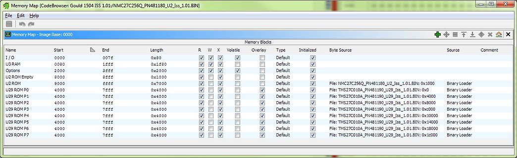
 Bild
Bild
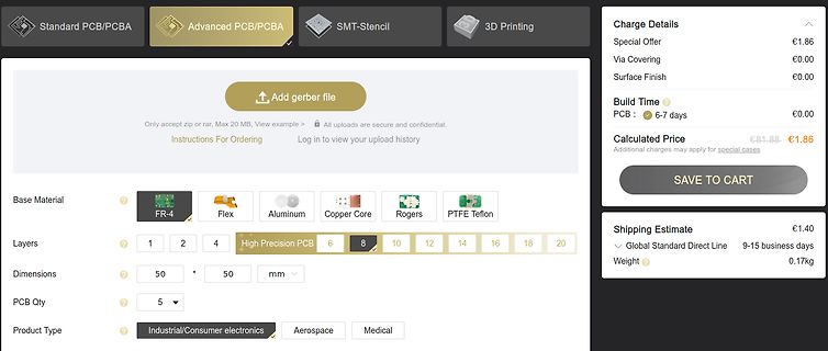
 Bild
Bild