-
Datei
Displayinitialisierung_16F877A_Puffer_Check_fix.asm
SSPSTAT config4 btfss SSPSTAT,BF ; Data transfer complete? (Buffer Full?) goto config4 ; if not, check again BANKSEL SSPBUF ; BANK0 movf SSPBUF,W ; Get Data from SSPBUF ; ; Throw it away bcf DC movlw 0x14 movwf SSPBUF btfsc SSPCON,7 bsf COLLED BANKSEL
in „[PIC]Probleme bei SPI Übertragung“ · Mikrocontroller und Digitale Elektronik ·
-
Datei
Displayinitialisierung_16F877A_abfragen_fix.asm
SSPSTAT config4 btfss SSPSTAT,BF ; Data transfer complete? (Buffer Full?) goto config4 ; if not, check again BANKSEL SSPBUF ; BANK0 movf SSPBUF,W ; Get Data from SSPBUF ; ; Throw it away bcf DC movlw 0x14 movwf SSPBUF btfsc SSPCON,7 bcf COLLED BANKSEL
in „[PIC]Probleme bei SPI Übertragung“ · Mikrocontroller und Digitale Elektronik ·
-
Datei
Displayinitialisierung_16F877A_abfragen_fix.asm
SSPSTAT config4 btfss SSPSTAT,BF ; Data transfer complete? (Buffer Full?) goto config4 ; if not, check again BANKSEL SSPBUF ; BANK0 movf SSPBUF,W ; Get Data from SSPBUF ; ; Throw it away bcf DC movlw 0x14 movwf SSPBUF btfsc SSPCON,7 bcf COLLED BANKSEL
in „[PIC]Probleme bei SPI Übertragung“ · Mikrocontroller und Digitale Elektronik ·
-
PDF
Datenblatt_ST24C02.pdf
acknowledge the receipt of the 8 bits of data. the data as a receiver. The device that controls the data transfer is known as the master and the other Data Input. During data input the ST24/25x02 as the slave. The master will always initiate a data sample the SDA bus signal on the rising edge of transfer and
in „PIC I2C EEPROM beschreiben“ · Mikrocontroller und Digitale Elektronik ·
-
PDF
24c04_V2.pdf
data as a receiver. The device that controls the Data Input. During data input the ST24/25x04 data transfer is known as the master and the other sample the SDA bus signal on the rising edge of as the slave. The master will always initiate a data the clock SCL. Note that for correct device opera- transfer
in „I²C - EEPROM's (24C04 ...)“ · Mikrocontroller und Digitale Elektronik ·
-
PDF
eeprom_24lc65_i2c.pdf
device. 3.0 BUS CHARACTERISTICS The following bus protocol has been defined: 3.5 Acknowledge • Data transfer may be initiated only when the bus Each receiving device, when addressed, is obliged to is not busy. generate an acknowledge after the reception of each • During data transfer, the data line must
in „64K EEPROM 24LC65 Adressierung“ · Mikrocontroller und Digitale Elektronik ·
-
PDF
tmp175.pdf
, defines a START condition. Each data transfer is initiated with a clock pulse. Setup and hold times must be taken into account. On a master receive, the termination of the data START condition. transfer can be signaled by the master generating a Stop Data Transfer: A change in the state of the SDA line Not-Acknowledge on the last byte that has been from LOW to HIGH while the SCL line is HIGH defines a transmitted by the slave. STOP condition. Each data transfer
in „Temperaturmessung mit dem LM75“ · Mikrocontroller und Digitale Elektronik ·
-
Datei
uartporb.c
-----------main part ----------------------------------------- void main (void) { unsigned char transfer[16]; UART_init(); //init UART UART_recv(); //received buffer memmove(transfer,rec_buff,16); //copy buffer to transfer UART_transmitt(transfer); // transmitt received buffer }
in „Variable laezst sich in SIG_UART_RECV nicht veraendern“ · Mikrocontroller und Digitale Elektronik ·
-
Datei
LEDtest.asm
Routine für Timer 1 Overflow RJMP TIME0_OVFL ;Routine für Timer 0 Overflow RJMP SPI_HANDLE ;SPI - Transfer beendet RJMP UART_RxC ;UART: Byte empfangen RJMP UART_DRE ;UART: Datenregister leer RJMP UART_TxC ;UART: Transfer beendet RJMP ANA_COMP ;Analog-Komparator ;****************************************
in „TIMER-Problem“ · Mikrocontroller und Digitale Elektronik ·
-
Datei
cpe_main.c
element count */ ) ); set_interrupts_dma(); DMA_start(hDma1); /* Start DMA channel 1 */ } while (!transfer_done); /* after transfer is finished, channel is closed. */ DMA_close(hDma1); } void /* Set the interrupts */ set_interrupts_dma(void) { IRQ_nmiEnable(); IRQ_globalEnable(); IRQ_disable(IRQ_EVT_DMAINT1
in „TMS320C6203 und CC2: DMA transfer von und zu internal memory“ · Digitale Signalverarbeitung / DSP / Machine Learning ·
-
PDF
Datenprotokoll_P03-3-RS485-CET.pdf
11 Transfer protocol 3. Transfer protocol All characters and/or digits are based on the ASCII standard, i.e. every reading pro- cessed internally as an integer or float value will always be broken down into and
in „Daten lesen auf dem RasPI3 über RS485“ · Mikrocontroller und Digitale Elektronik ·
-
PDF
S6D0154X_Data_Sheet_Rev1.00.pdf
Display Driver IC Transfer Synchronization Figure 84. Transfer Synchronization Function in 6-bit RGB Interface mode Note. The figure above shows Transfer Synchronization functions for 6bit RGB Interface. S6D0154 has a transfer
in „Nokia N95-Display“ · Mikrocontroller und Digitale Elektronik ·
-
PDF
Telit_Easy_GPRS_User__Guide_r9.pdf
.......................................................................49 3.3.2 Setting the FTP Transfer Type.....................................................................................................................49 3.3.3 FTP File transfer to the server...................................
in „Probleme mit AT-Befehlen für GPRS Datenübertragung TELIT 864“ · Mikrocontroller und Digitale Elektronik ·
-
PDF
DS_FT232H.pdf
wire. The master can send multiple data bytes so long as SS_n is active, if a unsuccessful data transfer occurs, i.e. a NAK happens on the MISO wire then the master should immediately abort the transfer by de-asserting SS_n. CLK SCLK READ WRITE SS_n WRITEDATA BUSTURNAROUND MIOSTXE#] CMD RDATA0 RDATA1
-
PDF
sl11hspec.pdf
............................................................15 2.3 EXAMPLE - USB TRANSACTION TO TRANSFER 128-BYTES OF DATA TO APERIPHERAL: ..................................16 2.3.1 USB Host Base Address [01H] ...........................................................................................
in „[V] SL11H, USS720E ua.“ · Markt ·
-
PDF
MCP3221.pdf
0000 0001 (1) 0000 0000 0000 (0) AIN .5 LSB V -1.5 LSB 1.5 LSB DD V DD-2.5 LSB 2.5 LSB FIGURE 4-1: Transfer Function. 2003 Microchip Technology Inc. DS21732B-page 13 MCP3221 4.5 Differential Non-Linearity (DNL) 4.8 Gain Error In the ideal A/D converter transfer function, each code The gain error determines
in „Suche Bauteilbezeichnung 5-Pin SOT-23 mit "S1SD" Marking“ · Mikrocontroller und Digitale Elektronik ·
-
Datei
Tastertest.asm
Routine für Timer 1 Overflow RJMP TIME0_OVFL ;Routine für Timer 0 Overflow RJMP SPI_HANDLE ;SPI - Transfer beendet RJMP UART_RxC ;UART: Byte empfangen RJMP UART_DRE ;UART: Datenregister leer RJMP UART_TxC ;UART: Transfer beendet RJMP ANA_COMP ;Analog-Komparator ;****************************************
in „Tasten entprellen“ · Mikrocontroller und Digitale Elektronik ·
-
Datei
Tastertest.asm
Routine für Timer 1 Overflow RJMP TIME0_OVFL ;Routine für Timer 0 Overflow RJMP SPI_HANDLE ;SPI - Transfer beendet RJMP UART_RxC ;UART: Byte empfangen RJMP UART_DRE ;UART: Datenregister leer RJMP UART_TxC ;UART: Transfer beendet RJMP ANA_COMP ;Analog-Komparator ;****************************************
in „Tasten entprellen“ · Mikrocontroller und Digitale Elektronik ·
-
Datei
FTDI_FUNCTIONS.c
FT_OK) { printf("Latency is set\r\n"); } else { printf("FT_SetLatencyTime FAILED! \r\n"); } DWORD InTransferSize = 0x10000; DWORD OutTransferSize = 0x10000; ftStatus = FT_SetUSBParameters(ftHandle, InTransferSize, OutTransferSize); if (ftStatus == FT_OK) { printf("Size is set\r\n"); } else { printf("FT_SetUSBParameters
-
Datei
lsusb.txt
Endpoint Descriptor: bLength 7 bDescriptorType 5 bEndpointAddress 0x01 EP 1 OUT bmAttributes 3 Transfer Type Interrupt Synch Type None Usage Type Data wMaxPacketSize 0x0200 1x 512 bytes bInterval 1 Endpoint Descriptor: bLength 7 bDescriptorType 5 bEndpointAddress 0x82 EP 2 IN bmAttributes 3 Transfer
in „AVR ICE3 mit avarice unter Ubuntu 18.04“ · Mikrocontroller und Digitale Elektronik ·
-
PDF
Project_ideas.pdf
cores using duplex or three cores using simplex communication at the same time. This acts as DMA to transfer data from/to RAM between the involved cores without any impact of the running cores. A base address is set by the sender and by the receiver and the size of data to transfer is controlled by sender
in „Mitstreiter für RISC-V Mikrocontrollers gesucht“ · FPGA, VHDL & Co. ·
-
PDF
app-note_HIP_4081A.pdf
the maximum High Voltage Level-shifter (charge transfer) value, the voltage droop on the bootstrap supply will be only In practice, the high voltage level-shifter and charge transfer about 0.5V losses are small compared to the gate drive charge transfer
in „HIP 4081 Verständnisprobleme“ · Mikrocontroller und Digitale Elektronik ·
-
PDF
21709c_EEPROM.pdf
data in a first-in first-out (FIFO) The following bus protocol has been defined: fashion. Data transfer may be initiated only when the bus is not busy. 3.5 Acknowledge During data transfer, the data line must remain stable whenever the clock line is high. Changes in Each receiving device, when addressed
in „EEPROM mit Infineon XC2200 ueber IIC benutzten“ · Mikrocontroller und Digitale Elektronik ·
-
PDF
21709c.pdf
data in a first-in first-out (FIFO) The following bus protocol has been defined: fashion. Data transfer may be initiated only when the bus is not busy. 3.5 Acknowledge During data transfer, the data line must remain stable whenever the clock line is high. Changes in Each receiving device, when addressed
in „24LC02B mit (scheinbar) seltsamer Adressierung“ · Mikrocontroller und Digitale Elektronik ·
-
PDF
Midas.pdf
Clock line (SCL). Both lines must be connected to a positive supply via a pull-up resistor. Data transfer may be initiated only when the bus is not busy. BIT TRANSFER One data bit is transferred during each clock pulse. The data on the SDA line must remain stable during the HIGH period of the clock pulse
in „Display mit SI7032: Wie Busy Flag lesen?“ · Mikrocontroller und Digitale Elektronik ·
-
PDF
BF998.pdf
drain-source voltage 12 V D drain current 30 mA Ptot total power dissipation 200 mW yfs forward transfer admittance 24 mS Cig1-s input capacitance at gate 1 2.1 pF Crs reverse transfer capacitance f = 1 MHz 25 fF F noise figure f = 800 MHz 1 dB Tj operating junction temperature 150 C 1996
in „Schaltung mit BF998“ · Analoge Elektronik und Schaltungstechnik ·
-
PDF
TSC2003.pdf
leave the data line HIGH to Figure 9: enable the master to generate the STOP condition. • Data transfer may be initiated only when the bus is not busy. Figure 9 details how data transfer is accomplished on the I C bus. Depending upon the state of the R/W bit, two types of • During data transfer, the
in „Hilfe mit Touchscreen“ · Mikrocontroller und Digitale Elektronik ·
-
Datei
debug_error.asm
0d b4 in r0, 0x2d ; 45 44a: 07 fe sbrs r0, 7 44c: fd cf rjmp .-6 ; 0x448 <spi_transfer_byte+0x2> return SPDR; 44e: 8e b5 in r24, 0x2e ; 46 } 450: 08 95 ret 00000452 <spi_transfer>: // Writes an byte-array of len bytes to target device and returns the bytes received void spi_transfer
in „Fehler bei einfacher Integer-Division?“ · Mikrocontroller und Digitale Elektronik ·
-
Datei
max31865.ino
registeraddress via SPI. */ void spi_write(byte address, byte value) { digitalWrite(CS_PIN, LOW); SPI.transfer(WRITE_MODE + address); SPI.transfer(value); digitalWrite(CS_PIN, HIGH); } /** * Reads from the given registeraddress via SPI and returns * the value. */ byte spi_read(byte address) { digitalWrite(CS_PIN, LOW); SPI.transfer(READ_MODE + address); byte value = SPI.transfer(0x00); digitalWrite(CS_PIN, HIGH); return value; } /** * Sends the given configuration to the MAX31865. */ boolean send_config(byte configuration) {
in „MAX31865 + PT100 kommuniziert nicht mit Arduino“ · Mikrocontroller und Digitale Elektronik ·
-
PDF
DS_LTV8X6.pdf
LITE-ON TECHNOLOGY CORPORATION Property of LITE-ON Only FEATURES * Current transfer ratio January 2010 ( CTR : MIN. 50% at I F=5mA, V CE=5V ) * High input-output isolation voltage ( Viso=5,000Vrms ) * Response time ( r: TYP. 4 s at V CE=2V, I C=2mA, R L =100 ) * Dual-in-line package
in „Problem mit Optokoppler“ · Mikrocontroller und Digitale Elektronik ·
-
PDF
RM-MPU-3300.pdf
Slave 0 are set as either read or write operations by the I2C_SLV0_RW bit. When this bit is 1, the transfer is a read operation. When the bit is 0, the transfer is a write operation. 2 I2C_SLV0_ADDR is used to specify the I C slave address of Slave 0. Data transfer starts at an internal register within
in „SPI Kommunikation mit MPU3300“ · Mikrocontroller und Digitale Elektronik ·
-
PDF
FR_Family_MB91F109.pdf
12-bit column address width • 2CAS/1WE, 2WE/1CAS selective DMA controller (DMAC) • 8 channels • Transfer incident/external pins/internal resource interrupt requests • Transfer sequence: Step transfer/block transfer/burst transfer/continuous transfer • Transfer data length: 8 bits/16 bits/32 bits selective
in „Fujitsu MB91F011 internal flash read/write“ · Mikrocontroller und Digitale Elektronik ·
-
Datei
myCode.txt
*************************************************************************************** void spiTransfer(int addr, uint8_t reg, uint8_t data) { //Create an array with the data to shift out int offset = addr*2; int maxbytes = 2*2; // 2*2(second 2 is the number of devices(MAX's)) for(int i=0;i<maxbytes
in „HD44780 emulieren“ · Mikrocontroller und Digitale Elektronik ·
-
PDF
UM_10120_LPC213x_User_Manual.pdf
activated. 11:8 BITS When bit 2 of this register is 1, this field controls 0000 number of bits per transfer: 1000 8 bits per transfer 1001 9 bits per transfer 1010 10 bits per transfer 1011 11 bits per transfer 1100 12 bits per transfer 1101 13 bits per transfer 1110 14 bits per transfer 1111 15 bits per
in „Zeichen im Interrupt empfangen“ · Mikrocontroller und Digitale Elektronik ·
-
PDF
UM10120_1.pdf
activated. 11:8 BITS When bit 2 of this register is 1, this field controls 0000 number of bits per transfer: 1000 8 bits per transfer 1001 9 bits per transfer 1010 10 bits per transfer 1011 11 bits per transfer 1100 12 bits per transfer 1101 13 bits per transfer 1110 14 bits per transfer 1111 15 bits per
in „Baudrate Abtastfrequenz“ · Mikrocontroller und Digitale Elektronik ·
-
Datei
bootloaderV1.a51
CODE XREF: HandleUsbEvents j mov A, USB_INT_ST ; RESERVED anl A, #0x3F jnz code_3B14 ljmp EP0OutTransfer ; --------------------------------------------------------------------------- code_3B14: ; CODE XREF: HandleUsbEvents+A j add A, #0xE0 ; 'à' jnz code_3B1B ljmp EP0InTransfer ; --------------------
in „uC für 0,20€ CH552 / CH554 von WCH Billig Micro mit USB Funktion, Chip vorstellung“ · Mikrocontroller und Digitale Elektronik ·
-
PDF
KS0074.pdf
instruction. KS0074 34COM/80SEG DRIVER & CONTROLLER FOR DOT MATRIX LCD INTERFACE WITH MPU KS0074 can transfer data in bus mode (4-bit or 8-bit) or serial mode with MPU. Hence, both types of 4 or 8-bit MPU can be used. In case of 4-bit bus mode, data transfer is performed by twice to transfer 1 byte data.
in „Informationen gesucht: 3,3V Display HB24208 für AVR32 / NGW100“ · Mikrocontroller und Digitale Elektronik ·
-
Datei
Display.asm
vor dem Senden machen um nicht zu viele Daten zu senden PUSH u1 RCALL XDelay POP u1 ;**********Transfer-Init******* SBI DDRB, MRQ_OUT ;MRQ auf LOW ziehen; Transfer wird initiiert. LDI u1,150 ;Maximal 15000µs auf Reaktion vom TID warten WaitforSDALow: SBIS PINB,SDA_OUT ;Schaue ob das TID die Leitung
in „Hat schonmal einer ein Opel TID ->erfolgreich<-angesteuert ?“ · Mikrocontroller und Digitale Elektronik ·
-
Datei
Mailserver.txt
creation-date="Wed, 13 Mar 2013 09:07:08 GMT"; modification-date="Wed, 13 Mar 2013 09:07:08 GMT" Content-Transfer-Encoding: base64 MDA0OTE3MjcxMzA4NjQNCjAwNDkxNzExNDc4NzI5DQo= --_002_A9B497F625589942AB4D183E696C911F34A6F28E39DC01xxxxcoml_-- ---------------------------------------------------------------------
in „E-Mail als reinen Text versenden“ · Softwareentwicklung ·
-
Datei
ethernet-spi.cpp
SPDCR.BYTE = 0x20; /* SPLW=1 */ RSPI0.SPBR.BYTE = 3; // PCLK / 8 RSPI0.SPCMD0.WORD = 0x1781; // 8 bit transfer, lsb first RSPI0.SPPCR.BYTE = 0x20; // mosi idle fixed 0 RSPI0.SPCR.BIT.SPE = 1; RSPI0.SPCR2.BYTE = 0; } void spi_transfer_b(unsigned int b) { b &= 0x00FF; while(RSPI0.SPSR.BIT.IDLNF) ; RSPI0.SPDR
in „Jemand hier mal mit dem Renesas RX63N bzw. GR_SAKURA gearbeitet?“ · Mikrocontroller und Digitale Elektronik ·
-
Datei
GPIO_FLASH_WD.c
SPI.setClockDivider(SPI_CLOCK_DIV4); // Adjust as needed // Read Flash ID digitalWrite(FLASH_PIN_CS, LOW); SPI.transfer(0x9F); // Send RDID command uint8_t manufacturerID = SPI.transfer(0x00); uint8_t memoryType = SPI.transfer(0x00); uint8_t capacity = SPI.transfer(0x00); digitalWrite(FLASH_PIN_CS, HIGH); // Print
-
PDF
tmp95fy64f.pdf
in section . 95fy64_10e.doc 23 99/01/19 11:43 TOSHIBA Under Development TMP95FY64 Table 3.4(4) Transfer Format for Boot Program : For RAM Loader Byte Tool to TMP95FY64 transfer data Baud rate TMP95FY64 to Tool transfer data number BOOT Byte 1 Matching data(5 AH) 9600bps - (baud rate automatic setting
in „[S] Tools für TMP95FY64F von Toshiba“ · Mikrocontroller und Digitale Elektronik ·
-
PDF
24LC32A.pdf
been defined: write does occur it will replace data in a first-in first-out (FIFO) fashion. Data transfer may be initiated only when the bus is not busy. During data transfer, the data line must remain 3.5 Acknowledge Each receiving device, when addressed, is obliged to stable whenever the clock line
in „I2C Eeprom: Buskollisionen nach einem schnellen Reset“ · Mikrocontroller und Digitale Elektronik ·
-
PDF
WS0010.pdf
Bit MPU from which WS0010 is connected to, is capable of transferring 8 bits, then an 8- bit data transfer operation is executed. Otherwise, two 4-bit data transfer operations are needed to satisfy one complete data transfer. Under the 4-bit data transfer, DB4 to DB7 are used as bus lines. DB0 to DB3 are disabled. The data transfer between WS0010 and MPU is completed after two 4-bit data have been transferred. The Busy Flag must be checked (one instruction) after completion of the data transfer (that is, 4-bit data has been
in „Ansteuern eines OLED-Display: EA W162-X3LW“ · Mikrocontroller und Digitale Elektronik ·
-
Datei
main.asm
********************************************************************** ;* ;* FUNCTION ;* i2c_do_transfer ;* ;* DESCRIPTION ;* Executes a transfer on bus. This is only a combination of i2c_read ;* and i2c_write for convenience. ;* ;* USAGE ;* i2cadr - Must have the same direction as when i2c_start was
in „Probleme mit DS1307 und dessen Zeitausgabe“ · Mikrocontroller und Digitale Elektronik ·
-
Datei
LCD.c
Transfer */ /*************************/ void i2cStop() { DDR_LCD |= (1<<SCL)|(1<<SDA); SetLowSCL(); SetLowSDA(); SetHighSCL(); SetLowSDA(); SetHighSCL(); SetHighSDA(); } /*************************/ /* Write Transfer */ /*************************/ int i2cWrite(char a) { DDR_LCD |= (1<<SCL)|(1<<SDA); int i; int return_ack; for (i=0; i<8; i++) { SetLowSCL(); if (a & 0x80) SetHighSDA(); else SetLowSDA(); SetHighSCL
in „I2C Display Steuern“ · Mikrocontroller und Digitale Elektronik ·
-
Datei
quellcode.txt
np:BlinkPattern ENDIF BREAK 1 CASE #SLEEP3 LDA #2AH ; 3 kurz STA np:BlinkPattern BREAK 1 CASE #TRANSFER_BRK LDA #6AH ; 2 kurz, 1 lang STA np:BlinkPattern BREAK 1 ENDS RTS SetBrk MACRO LDA np:Flag ORA #2 STA np:Flag ENDM SetMark MACRO LDA np:Flag ORA #$10 STA np:Flag ENDM /***************************
in „"unexpected end of file encountered" unter IAR EW“ · Mikrocontroller und Digitale Elektronik ·
-
Datei
max31865Hani.ino
slaveSelectPin" name as well. */ void Write(byte w_addr, byte data) { digitalWrite(slaveSelectPin, LOW); SPI.transfer(w_addr); SPI.transfer(data); digitalWrite(slaveSelectPin, HIGH); } /** * Read function(byte ) accepts the register address to be read and * returns the contents of the register to the loop function */ byte Read(byte r_addr) { digitalWrite(slaveSelectPin, LOW); SPI.transfer(r_addr); // read from configuration register value = SPI.transfer(0x00); // dummy write to provide SPI clock signals to read digitalWrite(slaveSelectPin, HIGH); return value; } /** * get_Temp() function
in „MAX31865 + PT100 kommuniziert nicht mit Arduino“ · Mikrocontroller und Digitale Elektronik ·
-
PDF
Arbeitsweise_Pico_Fmeter2.pdf
RAM zu schreiben und somit für die anschließende Auswertung verfügbar zu machen. Bei jedem DMA-Transfer wird der Transfer-Zähler des DMA-Kanals dekrementiert. Dieser Zähler ist 32 Bit breit, wird einmalig auf den maximalen Wert von 0xffffffff gesetzt und liefert beim Vergleich „alter Wert“ – „neuer
-
 Bild
Bild
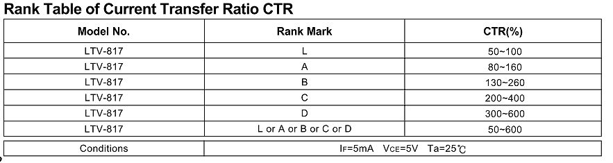
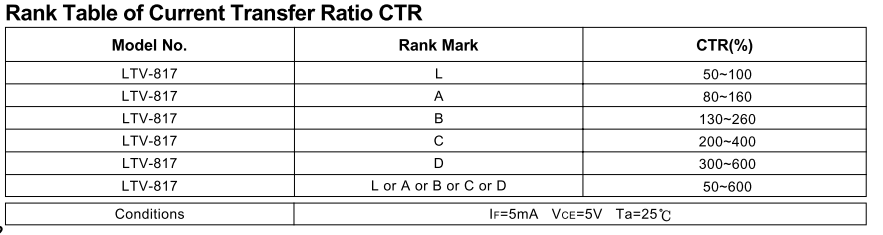
Tabelle der Current Transfer Ratio CTR für LTV-817
Rank Table of Current Transfer Ratio CTR Model No. Rank Mark CTR(%) LTV-817 L 50~100 LTV-817 A 80~160 LTV-817 B 130~260 LTV-817 C 200~400 LTV-817 D 300~600 LTV-817 L or A or B or C or D 50~600 Conditions IF=5mA VCE=5V Ta=25°C
in „Spannungsregler defekt, TNY, LM?“ · Analoge Elektronik und Schaltungstechnik · · Screenshots