-
PDF
CF-Karte.pdf
Jumper SV6 auf Int 7.5 gelegt werden. 2. AVR-Teil Als „intelligenter IO-Baustein“ nutze ich hier den Atmega 644, er hat mit 64kByte ROM genügend Speicherkapazität um das AVR-DOS aufzunehmen und ausreichend IO-Pins für die Anbindung der CF-Karte, sowie für den Datenaustausch mit der PIO. Die RS232 vom Atmega
in „Suche MOPPEL Projekt in Heft oder .PDF“ · Mikrocontroller und Digitale Elektronik ·
-
Datei
Baustelle.txt
stored directly to r31 ; next reads value for register or mode ; Author = Werner Braun ; Target = ATmega8 ; Date = 2012-02-04 ; ; PC6 = RESET ; PC4 = SDA TWI ; PC5 = SCL TWI ; PB1 = D/A Data out 8 ; PD0..7 = D/A Data out 0..7 ; ; .include "m8def.inc" ; ; Mode Codes .equ TriangleMode = 0x18;(11000 Bit
in „DDS normal ?“ · Mikrocontroller und Digitale Elektronik ·
-
Datei
OSZI.asm
Programm-Ablauf: ; 1. Der ADC wird gestartet und jeder 8 Bit-Messwert ; wird in den SRAM geschrieben (bei ATmega8 ca. 1000) ; 2. Anschließend werden alle Messwerte über USART ausgegebnen ; 3. nach einer kurzen Pause, denn der PC muss die Daten ; auch grafisch darstellen können, beeginnt alles wieder von vorn
in „einfaches DIGITAL- Oszilloskop (800 Datenpunkte) Assembler“ · Projekte & Code ·
-
Datei
Lichtorgel.ino
Entwickelt 2015 von Christof Rieger //sollte auf allen AVR-8 Arduinos laufen mit 16MHz und mindestens mit ATmega168 //Ein Geschenk an die Arduinogemeinde. Die Vermarktung des Cods ist verboten !!! //#include <LiquidCrystal.h> //Der Wert der überschritten werden muss, damit der Kanal aktiv wird (maximal 255) #
in „5 Kanal Digital-Lichtorgel für Arduino“ · Projekte & Code ·
-
Datei
AVR8_Burn_O_Mat_Config.xml
caption="4.0V (3.7V - 4.5V)" Fuse1="0" Fuse2="0"/> </BrownOutDetection> <OscillatorOptions Type="ATmega8" /> </AVR> <AVR name="m16" caption="ATmega16"> <Fuse name="OCDEN" bit="7" fuseByte="hfuse" default="1" desc="Enable OCD (on chip debug)" mode="expert"/> <Fuse name="JTAGEN" bit="6" fuseByte="hfuse
-
Datei
HW-PWM_an_3_Pins.c
/* Microcontroller: ATmega8515 Clock: 14,745 MHz AVR hardware: timer2 */ #include <avr/io.h> #include <util/delay.h> /// Number of probes for one period of sine wave #define WAVE_PROBES 256 /* predefined values */ uint8_t wave
in „Umschalten von 3 HW-PWM Kanälen beim ATMEGA8515“ · Mikrocontroller und Digitale Elektronik ·
-
Datei
adxl345_atmega168.c
200 1000 100 500 50 250 25 125 12,5 625 6,25 312 3,13 156 1,56 78 0,78 39 0,39 19 0,20 9 0,1 */ // atmega168 #ifndef SS #define SS 2 #endif #ifndef SCK #define SCK 5 #endif #ifndef MOSI #define MOSI 3 #endif #ifndef MISO #define MISO 4 #endif #define FEHLER 0 //PC0 #define VDD 1 //PC1 #define OK 2 //PC2
in „ADXL345 & SPI Kommunikationsproblem“ · Mikrocontroller und Digitale Elektronik ·
-
PDF
FreePDF_XP_File.pdf
X18 48 3 WR 33 21 PF0 R3 RESET RD 34 PG0 (WR) VCC 52 10 CON109 PF1 49 MM74HC02 PG2 43 PG1 (RD) VCC 64 9 CON108 PF2 50 GND 15k PG2 (ALE) AVCC 62 8 CON107 PF3 51 U2B RESET 20 AREF R2 7 CON106 PF4 52 RESET 330E 6 53 5 PEN 1 PEN GND 22 5 CON105 PF5 54 4 GND 53 4 CON104 PB5 55 6 23 XTAL2 GND 63 3 CON103 PB6 56 24 XTAL1 A 2 CON102 PB7 57 MM74HC02 VCC 1 58 U2C Q1 ATmega128-16AI V1 CON10 59 8 LED 60 10 V2 + C4 C5 C6 C7 C8 CON64 5V1 1u 100n 100n 100n 100n 9 12MHz K GND MM74HC02 A GND C1 C2 C3 A U2D 100n 22p 22p 11 Title 13 GND GND GND GND 12 Size Number Revision MM74HC02
-
Datei
Master3.bas
Steckdosen kommuniziert, und die Steuerung des multi-processor communication-mode übernimmt... $regfile = "m64def.dat" 'der Atmega 64 hat zwei UART-SChnittstellen für Kommunikation mit dem pc und den Steckdosen $crystal = 4000000 '$baud = 9600 'muss für beide Schnittstellen seperat eingestell werden ' USART 0
in „Bascom: Fehler beim compilieren“ · Mikrocontroller und Digitale Elektronik ·
-
Datei
main.c
// // Steuerung und Anzeigeeinheit Netzteil 10V; max 10A Linearregler // ATMEGA 32 - DIP40 // #define F_CPU 25000000 //25MHZ Quarz mit 22pF gegen Masse #include <avr/io.h> #include <util/delay.h> #include <avr/interrupt.h> #include <lcd.c> #include <stdlib.h> #define Reg_proportional
in „ATMEGA 32 mit LCD - Probleme mit Interrupt INT0“ · Mikrocontroller und Digitale Elektronik ·
-
Datei
HSV_RGB_10bitPWM.asm
------------------------------------------- ;HSB -> RGB Wandler, in AVR-Assembler, für ATiny und ATmega ;Kurzfeatures: (Details und ausführliche Erläuterungen im Quelltext) ;------------------------------------------------------------------- ;*Codegrösse nur ca.300 Words auf Atiny, ca.280 auf ATmega
in „DMX - PWM generieren“ · Mikrocontroller und Digitale Elektronik ·
-
Datei
DB.c
-------------------* * * * Erstellt von st. Räbiger am 24.04.2012 * * Version 3b * * * * für ****ATmega8535-16AC**** * * -----------------------------------------------------------------------------------------------------* * * * Datenbank für ESJOG 3B * * * *-----------------------------------------
in „WinAVR compiliert nicht mehr richtig“ · Mikrocontroller und Digitale Elektronik ·
-
Datei
config.xml
caption="4.0V (3.6V - 4.5V)" BODEN="0" BODLEVEL="0"/> </BrownOutDetection> <OscillatorOptions Type="ATmega8"/> </AVR> <AVR name="m32" caption="ATmega32"> <Fuse name="OCDEN" bit="7" fuseByte="hfuse" default="1" desc="Enable OCD (on chip debug)" mode="expert"/> <Fuse name="JTAGEN" bit="6" fuseByte="hfuse"
in „Fuseeditor, grafische Benutzeroberfläche für AVRdude“ · Projekte & Code ·
-
Datei
Firmware_v1.2.c
DMX512 reception library * Version : v1.3 * Last updated : 13.04.09 * Target : Transceiver Rev.3.01 [ATmega8515] * Clock : 8MHz, 16MHz * * written by hendrik hoelscher, www.hoelscher-hi.de *************************************************************************** This program is free software; you can redistribute
in „DMX steuerbaren RGB LED PAR oder Pinnspot selber bauen“ · Mikrocontroller und Digitale Elektronik ·
-
Datei
Firmware_v1.2.c
DMX512 reception library * Version : v1.3 * Last updated : 13.04.09 * Target : Transceiver Rev.3.01 [ATmega8515] * Clock : 8MHz, 16MHz * * written by hendrik hoelscher, www.hoelscher-hi.de *************************************************************************** This program is free software; you can redistribute
in „DMX steuerbaren RGB LED PAR oder Pinnspot selber bauen“ · Mikrocontroller und Digitale Elektronik ·
-
Datei
test7.c
51, 51, 52, 52, 53, 53, 54, 54, 55, 55, 56, 56, 57, 57, 58, 58, 59, 60, 60, 61, 61, 62, 62, 63, 63, 64, 64, 65, 65, 66, 66, 67, 67, 68, 68, 69, 69, 70, 70, 71, 71, 72, 72, 73, 73, 74, 75, 75, 76, 76, 77, 77, 78, 78, 79, 79, 80, 80, 81, 81, 82, 82, 83, 83, 84, 84, 85, 85, 86, 86, 87, 87, 88, 89, 89, 90
in „Frage zu Interrupt“ · Mikrocontroller und Digitale Elektronik ·
-
Datei
test7.c
51, 51, 52, 52, 53, 53, 54, 54, 55, 55, 56, 56, 57, 57, 58, 58, 59, 60, 60, 61, 61, 62, 62, 63, 63, 64, 64, 65, 65, 66, 66, 67, 67, 68, 68, 69, 69, 70, 70, 71, 71, 72, 72, 73, 73, 74, 75, 75, 76, 76, 77, 77, 78, 78, 79, 79, 80, 80, 81, 81, 82, 82, 83, 83, 84, 84, 85, 85, 86, 86, 87, 87, 88, 89, 89, 90
in „Frage zu Interrupt“ · Mikrocontroller und Digitale Elektronik ·
-
Datei
debug_error.asm
rjmp .-20 ; 0x478 <spi_transmit+0x4> } } 48c: 08 95 ret 0000048e <__vector_2>: #if defined(__AVR_ATmega8__) || defined(__AVR_ATmega88A__) || defined(__AVR_ATmega168__) ISR( INT1_vect ) #else # error MCU MODEL NOT SUPPORTED #endif // defined(__AVR_ATmega8__) || defined(__AVR_ATmega88A__) || defined(__
in „Fehler bei einfacher Integer-Division?“ · Mikrocontroller und Digitale Elektronik ·
-
PDF
RESET-Stand-der-Dinge.pdf
AVR−Stamp Z180−Stamp PD5 RESET ATmega1281 Z8S180 10K ? R ECB Connector 64pol Steckerleiste ZRESET C26 1 ? ZRESET 2 S ECB Basiskarte
in „Z180-Stamp Modul“ · Mikrocontroller und Digitale Elektronik ·
-
Datei
mispav.htm
h3><a name="versionen"></a>Versionen</h3> <a href="../../../../h/home/html/etronik/atmel/atmel_c_atmega164p_324p_644p_doc7674.pdf">ATMega644P</a>: <a href="../../../../h/home/html/etronik/atmel/atmel_c_atmega164p_324p_644p_40002071A.pdf">(*)</a>: ROM: 64KiB 65536 (0x10000) Bytes, RAM:4KiB 4096 RAM <br> <a href="../../../../h/home/html/etronik/atmel/atmel_c_atmega328_328p_168a_168pa_88a_88pa_48a_48pa.pdf">Atmega328</a>: ROM: 32KiB 32768 (0x8000), RAM 2KiB 2048 <br> <a href="../../../../h/home/html/etronik/atmel/atmel_c_atmega32_complete_doc2503.pdf">Atmega32
in „Implementierung von Menüs auf alphanumerischen Displays“ · Mikrocontroller und Digitale Elektronik ·
-
Datei
config.h
************************************************* */ /* MCU clock */ #define CPU_FREQ F_CPU /* * ATmega 328/328P */ #if defined(__AVR_ATmega328__) #include "config_328.h" /* * ATmega 324P/324PA/644/644P/644PA/1284/1284P */ #elif defined(__AVR_ATmega324P__) || defined(__AVR_ATmega644__) || defined(__AVR_ATmega1284__) #include "config_644.h" /* * ATmega 640/1280/2560 */ #elif defined(__AVR_ATmega640__) || defined(__AVR_ATmega1280__) || defined(__AVR_ATmega2560__) #include "config_1280.h" /* * missing or unsupported MCU */ #else #error <<< No or wrong
-
Datei
config.h
************************************************* */ /* MCU clock */ #define CPU_FREQ F_CPU /* * ATmega 328/328P */ #if defined(__AVR_ATmega328__) #include "config_328.h" /* * ATmega 324P/324PA/644/644P/644PA/1284/1284P */ #elif defined(__AVR_ATmega324P__) || defined(__AVR_ATmega644__) || defined(__AVR_ATmega1284__) #include "config_644.h" /* * ATmega 640/1280/2560 */ #elif defined(__AVR_ATmega640__) || defined(__AVR_ATmega1280__) || defined(__AVR_ATmega2560__) #include "config_1280.h" /* * missing or unsupported MCU */ #else #error <<< No or wrong
-
PDF
RESET-Vorschlag.pdf
AVR−Stamp Z180−Stamp Vcc Vcc 4K7 ? 10K−100K R R Z8S180 RESET Q? BSS138 PD5 ATmega1281 IRLML2402 ? S ECB Connector 64pol Steckerleiste ZRESET C26 1 ? ZRESET S 2 ECB Basiskarte
in „Z180-Stamp Modul“ · Mikrocontroller und Digitale Elektronik ·
-
PDF
TransistorTester_eng_094k.pdf
display layout is changed from hFE= to B= to save space. 11. The differences of reference voltage ofATmega8,ATmega88,ATmega168 andATmega328 are applied as noted in the data sheet. You can also use the feature WITH_AUTO_REF with a Makefile option, in this case the reference Voltage is read out withADC. The
-
PDF
TransistorTester_eng_095k.pdf
display layout is changed from hFE= to B= to save space. 11. The differences of reference voltage ofATmega8,ATmega88,ATmega168 andATmega328 are applied as noted in the data sheet. You can also use the feature WITH_AUTO_REF with a Makefile option, in this case the reference Voltage is read out withADC. The
-
Datei
Neues_Textdokument.txt
enclose it in quotes. EXTRALIBDIRS = #---------------- External Memory Options ---------------- # 64 KB of external RAM, starting after internal RAM (ATmega128!), # used for variables (.data/.bss) and heap (malloc()). #EXTMEMOPTS = -Wl,-Tdata=0x801100,--defsym=__heap_end=0x80ffff # 64 KB of external RAM, starting after internal RAM (ATmega128!), # only used for heap (malloc()). #EXTMEMOPTS = -Wl,--section-start,.data=0x801100,--defsym=__heap_end=0x80ffff EXTMEMOPTS = #---------------- Linker Options ---------------- # -Wl,...: tell GCC
in „Fuse bei WinAvr“ · Mikrocontroller und Digitale Elektronik ·
-
Datei
AVR_328P_Timer2.asm.txt
Created: 19.03.2025 15:33:59 ; Author : Andreas ; C:\Program Files (x86)\Atmel\Studio\7.0\packs\atmel\ATmega_DFP\1.7.374\avrasm\inc\m328Pdef.inc ;.include "file" .device ATmega328P .EQU takt = 16000000 ; Systemtakt 16 MHz intern => 1 CPU clk = 62,5ns .equ T2Go = 250 ; T2 prevalue .DEF akku = r16 ; Arbeitsregister
in „Frage: 328p und Timer2/GPIO in assembler“ · Mikrocontroller und Digitale Elektronik ·
-
Datei
Handy-Waehlscheibe_V0.30c_Layout.bas
5,5mA, Sleepmodus wenn Akku leer: 2mA | '| 4x 1,2V Akkuzellen, Abschaltung bei <= 3,8V | '| Nur ATMega88V verwenden wegen der Sleep-Config | '| | '| | '| Software Version 1.30a Layout-Version !!!!! | '| Layout Version 1.00 ====================== | '| Schaltplan Version 1.00 | '| | '| Funktionen per
in „ATMega88V-Schaltung: 20% Fehlverhalten“ · Mikrocontroller und Digitale Elektronik ·
-
Datei
Handy-Waehlscheibe_V0.30c_Layout.bas
5,5mA, Sleepmodus wenn Akku leer: 2mA | '| 4x 1,2V Akkuzellen, Abschaltung bei <= 3,8V | '| Nur ATMega88V verwenden wegen der Sleep-Config | '| | '| | '| Software Version 1.30a Layout-Version !!!!! | '| Layout Version 1.00 ====================== | '| Schaltplan Version 1.00 | '| | '| Funktionen per
in „ATMega88V-Schaltung: 20% Fehlverhalten“ · Mikrocontroller und Digitale Elektronik ·
-
Datei
boot.c
volatile("nop"); } while(1); } /* --------- do.bat --------- echo compile... avr-gcc -g -Os -mmcu=atmega16 -c boot.c echo link... avr-gcc -g -mmcu=atmega16 -Wl,-Map,boot.map,--cref,--section-start=.bootloader=0x1c00 -o boot.elf boot.o echo creating lst file... avr-objdump -h -S -d boot.elf > boot.lst
in „bootloader section in c“ · Mikrocontroller und Digitale Elektronik ·
-
Datei
partlist.txt
100n C0805 rcl (30.1625 115.8875) R90 CON1 SCDA5A0201 SCDA5A0201 SCDA5A0201 (20.6375 30.48) R0 IC1 ATmega88-20P DIL28-3 atmel (37.465 50.165) R270 IC2 74S08D SO14 74xx-eu (18.0975 18.7325) MR90 IC3 FT232RL SSOP28 ftdichip (44.7675 21.59) R180 IC4 ATmega88-20P DIL28-3 atmel (20.32 99.695) R0 IC7 74AC08D
in „CP/M auf ATmega88“ · Mikrocontroller und Digitale Elektronik ·
-
Datei
M8_Test_1.c
/*ATmega8 Lauflicht auf PORTD (PORTB von ATmega8 hat nur 6 I/O Pins auf STK500 !) Frequenz über Poti an PC0 regelbar Programme über Taster an PB0 durchschaltbar Taster mit Routine von P. Dannegger entprellt
in „mega8 Tastenentprellung“ · Mikrocontroller und Digitale Elektronik ·
-
Datei
main.c
<avr/eeprom.h> #include <avr/wdt.h> #include <math.h> //AVR-Typenabhänggikeit #if defined(__AVR_ATmega48__) #define MCU_STATUS_REG MCUCR #elif defined(__AVR_ATmega88__) #define MCU_STATUS_REG MCUCR #define UseM8 #elif defined(__AVR_ATmega168__) #define MCU_STATUS_REG MCUCR #define UseM8 #else #define
-
PDF
B-1220.pdf
sorgt, sodass dieser Dualgate-MOSFET maximal verstärkt. Löten Sie ein: R61 10 kΩ R62 10 kΩ R63 47 Ω R64 100 Ω C72 5,6 pF C69 18 pF C64 1 nF C65 1 nF C68 39 pF C70 15 pF C71 1,5 pF C66 100 nF L12 Spule rot L11 Spule rot L10 Spule rot T13 BF961 (Einbaulage beachten) Abgleich und Test: Spannung an Gate 2
in „JR 78 von DF5FC Schaltbild gesucht“ · HF, Funk und Felder ·
-
Datei
bootload.lst
m168def.inc" 29 30 ; set the FirstBootStart fuse on these AVRs: 31 ;.include "m32def.inc" 32 ;.include "m64def.inc" 33 ;.include "m644def.inc" 34 ;.include "m128def.inc" 35 ;.include "m1281def.inc" 36 ;.include "m2561def.inc" 37 38 39 ; remove comment sign to exclude API-Call: 40 ; only on ATmega >= 8kB supported
in „Peter Danneggers Bootloader (fastboot) für AVR-GCC-Toolchain“ · Projekte & Code ·
-
Datei
avarice_log.txt
Serial number: 00:b0:00:00:29:6a Reported JTAG device ID: 0x9403 Configured for device ID: 0x9403 atmega16 -- Matched with atmega16 JTAG config complete. Erasing program memory. Erase complete. Preparing the target device for On Chip Debugging. Disabling lock bits: LockBits -> 0xff Enabling on-chip debugging
in „Debuggen in Eclipse geht nicht GDB <-> AVaRICE problem“ · Mikrocontroller und Digitale Elektronik ·
-
 Bild
Bild
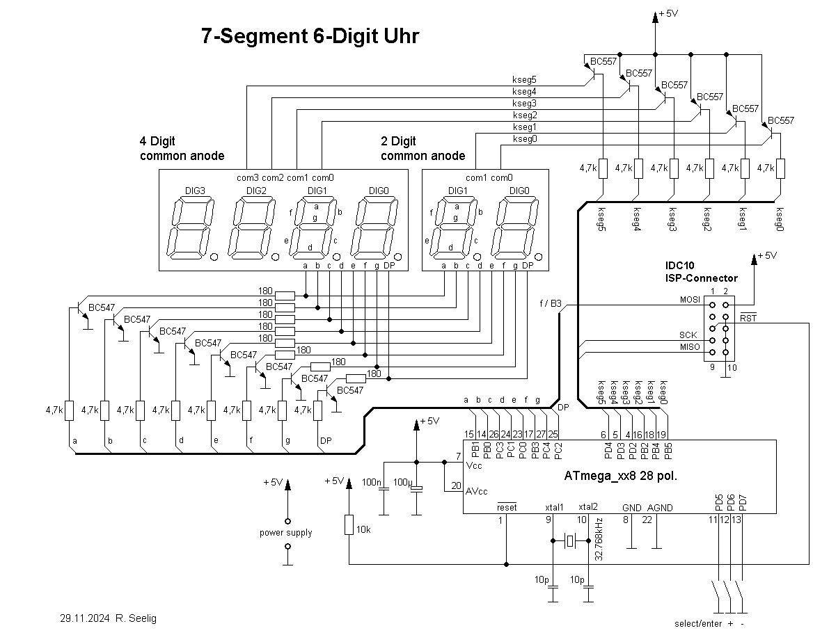
Schaltplan einer 7-Segment 6-Digit Uhr
DIG2, DIG1, DIG0, BC547, BC557, 4,7k, kseg5 bis kseg0, IDC10 ISP-Connector, MOSI, SCK, MISO, RST, ATmega_xx 28 pol., PB0 bis PB7, PD5 bis PD7, GND, AGND, Vcc, AVcc, reset, xtal1, xtal2, 32/64kHz, 10p, 100µ, 10k, +5V, 29.11.2024 R. Seelig
in „LED-Uhr mit Attiny26“ · Mikrocontroller und Digitale Elektronik · · Schaltpläne
-
PDF
Praktikum_SMRM_Versuch4.pdf
Um diese mit den Signalverarbeitungsabläufen eines angeschlossenen Mikrocontrollers (wie unseres ATmega328PB) zu synchronisieren, kann das PPG-Modul bei Vorhandensein neuer Messdaten im Pufferspeicher einen Interrupt auslösen. Hierzu existiert am PPG-Modul ein Interrupt-Ausgangssignalanschluss, der mit
in „PPG-Sensor (MAX301 102) über I2C-Schnittstelle (Hilfe)“ · Mikrocontroller und Digitale Elektronik ·
-
Datei
Beispiel_FFT_fuer_SerialComInstruments.txt
' Beispiel FFT für SerialComInstruments ' avr.device = atmega168p avr.clock = 22118400 avr.stack = 100 uart.baud = 460800 uart.Send.enable #Library "Library/Adc.interface" adc.enable adc.clock = 64 adc.mode = single adc.reference = avcc Adc.Channel = 0 Avr.Interrupts.Enable
in „Projekt: Virtuelle Instrumente an serielle Schnittstelle“ · Projekte & Code ·
-
Datei
MultiDS18S20_0.2.bas
=============================================== $regfile = "m8def.dat" $crystal = 14318180 'Mini-Atmega 4-Platine (mit LCD) $baud = 9600 Declare Function Dg_ds18s20(byval Sc(9) As Byte) As Integer 'Umrechnung in Grad Declare Function Dg_ds18b20(byval Sc(9) As Byte) As Integer 'Umrechnung in Grad Declare
in „Was brauche ich von der Seriennummer DS18B20?“ · Mikrocontroller und Digitale Elektronik ·
-
Datei
Oberschlitten2.asm
* * ;* Projekt: : Antrieb Oberschlitten * ;* Datum : 30-12-2016 Version : 1.24 * ;* Target MCU : ATmega8 * ;* * ;* Eingänge : * ;* Ausgänge : * ;* Mit Taste1 links+schnell oder Taste2 rechts+langsam * * ;* * ;******************************************************************************** ;**********
in „Timer0 und Timer1 funktionieren nicht gemeinsam“ · Mikrocontroller und Digitale Elektronik ·
-
Datei
AVR.html
" rowspan="1" style="width: 8.485%;" class="hcp11" width="8.485%"> <p class="hcp2" align="right">ATmega64</p> </td> <td colspan="1" rowspan="1" style="width: 6.776%;" class="hcp13" width="6.776%"> <p class="hcp14" align="center">a</p> </td> <td colspan="1" rowspan="1" style="width: 5.598%;" class="hcp13
in „Billige Alternative zu AVR STK 500 oder Wie brenne ich günstig mein Programm auf den Mikrochip?“ · Mikrocontroller und Digitale Elektronik ·
-
PDF
fjrx85Doc.pdf
www.cadsoft.de) Datenblätter zu SA602, TS912, 74HC93 usw. z.B. auf www.alldatasheets.com Datenblatt zu ATMega168 (knapp 400 Seiten): www.atmel.com -> suchen nach ‚ATMega168‘ Nick Roethe, DF1FO: 80m-SMD-Peilempfänger Version 5 Dokumentenname fjrx85.doc Stand 14.9.2017 Seite 20 Anhang : Stückliste In <..> ist
-
 Bild
Bild
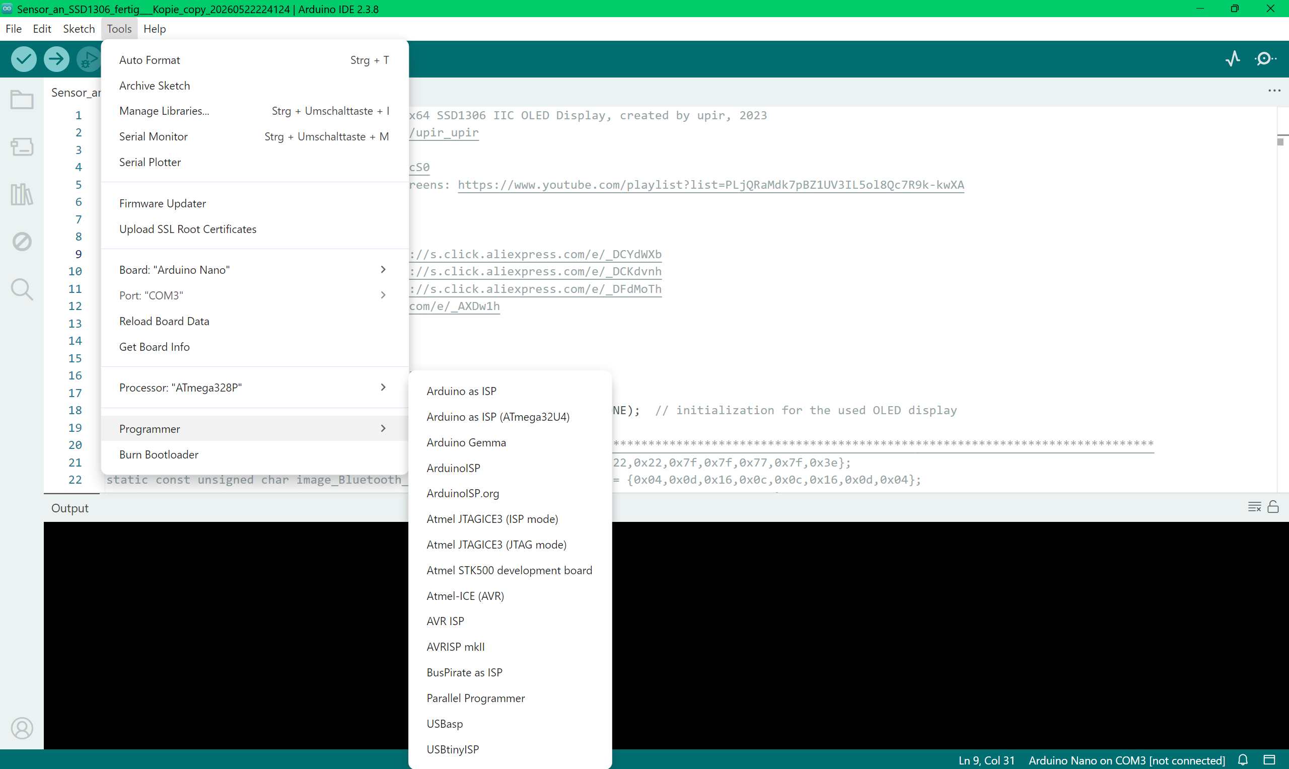
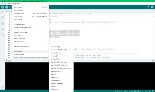
Arduino IDE Menü und Code-Editor
2026052224124 | Arduino IDE 2.3.8 File Edit Sketch Tools Help Sensor_asd1306_fermg.copy_2026052224124 x64 SSD1306 IIC OLED Display, created by upir, 2023 upir_upir https://www.youtube.com/playlist?list=PLJQRaMdk7pBZ1UV3IL5ol8Qc7R9k-kwXA Arduino as ISP Arduino as ISP (ATmega32U4) Arduino Gemma ArduinoISP
in „Suche Arduino kompatiblen Bootloader für ATmega8 mit 8Mhz intern“ · Mikrocontroller und Digitale Elektronik · · Screenshots
-
Datei
timer0.h
bis 0 macht dann Interrupt //und CountMilliseconds wird um eins hochgezählt. Alle 1ms. Durch Teiler 64 und Zählerstand -115 //ergiebt sich dieser Wert. // //timer0.h //Angepasst für Atmega8 + 32 //Datum: 18.10.2008 //Version: 2.0 //Version: 2.1 30.12.2008 Zähler auf char geändert wegen Keyboard //****
in „If wird nicht ausgeführt“ · Mikrocontroller und Digitale Elektronik ·
-
 Bild
Bild
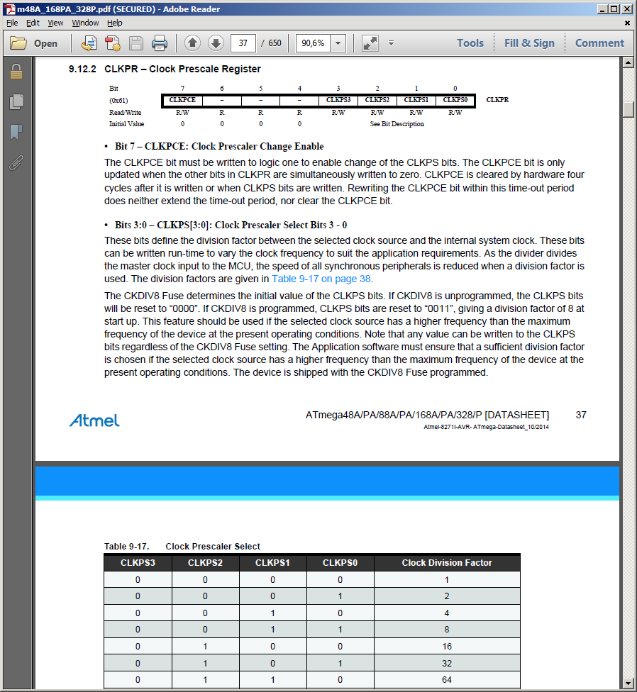
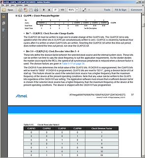
Ausschnitt aus einem Atmel ATmega Datenblatt
CLKPS3 CLKPS2 CLKPS1 CLKPS0 CLKPR Read/Write R/W - - R R R/W R/W R/W Initial Value 0 0 0 Atmel ATmega48A/PA/168A/PA/328/P [DATASHEET] Table 9-17. Clock Prescaler Select CLKPS3 CLKPS2 CLKPS1 CLKPS0 Clock Division Factor 0 0 0 1 0 0 0 1 2 0 0 1 0 4 0 0 1 1 8 0 1 0 0 16 0 1 0 1 32 0 1 1 0 64
in „ATMega328P nicht mehr programmierbar“ · Mikrocontroller und Digitale Elektronik · · Screenshots
-
Datei
KlimaSensorKomm.c
Taktsignal. Für weitere Infos siehe "12.2 - Ports as General Digital I/O" in der Beschreibung des ATMega32 #define SHT75_DATA_1 DDRC &= ~(1 << SHT75_DATA) //schreibt eine "1" auf den Bus (setzt den Pin hochohmig). Ein externer Pullup zieht den Bus auf High #define SHT75_DATA_0 DDRC |= (1 << SHT75_DATA
in „SHT75 - CRC Check: Ich finde den Fehler nicht“ · Mikrocontroller und Digitale Elektronik ·
-
Datei
PingPong1.bas
'PingPong für ATmega8 'Fabian Kainka 2009 $crystal = 8000000 $regfile = "m8def.dat" $hwstack = 64 $swstack = 16 $framesize = 64 Config Portc = 15 'PORTC als AD-Eingang Config Portb = Output Config Portd = 255 Dim X(14)
in „Hilfe! Ping Pong: Code verstehen und umschreiben“ · Mikrocontroller und Digitale Elektronik ·
-
Datei
timer0.h
bis 0 macht dann Interrupt //und CountMilliseconds wird um eins hochgezählt. Alle 1ms. Durch Teiler 64 und Zählerstand -115 //ergiebt sich dieser Wert. // //timer0.h //Angepasst für Atmega8 + 32 //Datum: 18.10.2008 //Version: 2.0 //Version: 2.1 30.12.2008 Zähler auf char geändert wegen Keyboard //Version
in „If wird nicht ausgeführt“ · Mikrocontroller und Digitale Elektronik ·
-
Datei
RSR232.c
#include <avr/io.h> // ATmega128 MCU #include <stdio.h> // Standard Input/Output functions int main(void) { // RS232 Buffer // USART initialization UCSR0A=0x00; // Communication Parameters: 8 Data, 1 Stop, No Parity UCSR0B=0x18
in „atmega 128 RS232 benutzen“ · Mikrocontroller und Digitale Elektronik ·